
 Electrical Wiring Basics
Chapter 14 of How to Build Your Dream Home © 2020 InspectApedia.com
- POST a QUESTION or COMMENT about how to identify the architectural style of buildings and building components
This article series provides an updated version of Hubbard Cobb's Your Dream Home, illustrated by Sigman-Ward, first published by Wm. H. Wise & Co. New York, 1950.
From site selection and obtaining financing through each step in construction of a single family home the simple procedures and drawings in this book are still useful for anyone building or repairing a home or other small structure.
InspectAPedia tolerates no conflicts of interest. We have no relationship with advertisers, products, or services discussed at this website.
- Daniel Friedman, Publisher/Editor/Author - See WHO ARE WE?
Home Electrical Wiring Procedures
 This is Chapter 14 of BUILD YOUR DREAM HOME at InspectApedia.com - online encyclopedia of building & environmental inspection, testing, diagnosis, repair, & problem prevention advice.
This article is also available as ELECTRICAL WIRING INSTALLATION BASICS [eBook] or as a PDF image at THE ELECTRICAL WIRING [PDF] original page images.
The rough electric wiring, like the plumbing system, should be installed before the interior walls are covered with plaster or wallboard.
How much, if any, of the electrical wiring can be done by the home-builder himself will depend on local regulations. Practically all well settled communities have their own codes governing the installation of electric wiring. Some of these codes will insist that this type of work be done only by a licensed electrician.
Other codes, not quite so strict will allow any one to do the wiring providing it passes inspection by a building or housing inspector. Your electric power company will be interested in howr the house is wired, and unless the wiring meets with its approval, the power company will not bring in and connect their lines.
Last but not least, home fire-insurance concerns may refuse to insure a home that is not, in their opinion, adequately wired.
Checks Before Starting to Run Electrical Wires
All this means that you have quite a lot of checking up to do before you can go ahead with the installation.
This business of who is to do the wiring should be looked into well before you reach the point of doing the actual work because if the work must be done by an electrician, you may not be able to get one at short notice and then you are going to be held up all along the line.
First of all, check with your local building authorities and find out if you are allowed to do this work yourself. If you find that you can, get a copy of the local wiring codes, because wiring methods that meet the approval of one community will not necessarily meet with approval in others. If there is no special local code, the wiring should conform with the National Electric Code, which contains the minimum requirements for safe residential wiring. Wiring methods outlined in
this chapter meet with these requirements and, therefore, can be used in all cases where there is no local code that supersedes the National Electric Code.
After you have found out about local codes, check with your local power concern and your local fire-insurance agent. You mav find that their only
requirement is that the final installa- electrician before the power is con-tion must be checked over by a licensed nected.
WIRING METHODS
While there are many materials used for wiring, the three that are usually accepted for residential wiring are rigid conduit, armored or BX cable and nonmetallic sheathed cable.
Rigid Conduit
This type of wiring is approved by almost every code but it is also the most expensive type and requires the most work to install. It consists of steel-pipe conduits, which are fastened together in the same fashion as water pipes. See Fig. 1. After these conduits are installed, electric wires are pulled through them. The conduits are soft
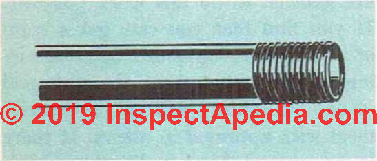
Fig. 1. A piece of rigid conduit.
enough to permit bending. Local codes will often require the use of conduits in damp locations, such as basements.
Rigid conduit comes in 10-foot sections. It has a finish that is either black enamel or galvanized. The galvanized type should be used where there is the possibility of moisture. The conduit can be cut in the same manner as steel water-pipes and with the same type of equipment.
After a length has been cut to size, the cut end should be reamed out to remove any sharp burrs left by the cutter. This is a very important step because if these burrs are left inside the pipe, they may damage the insulation on the wires as the wires are pulled through the conduit. Unlike water pipes, the threads on conduits do not taper but are perfectly straight.
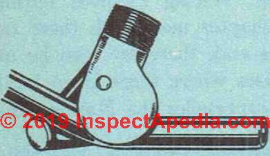
Fig. 2. A bender that is used for bending conduit.

Fig. 3. Fish tape.
Therefore, special thread-cutting dies should be used and not the ones intended for plumbing installation. There are special elbow bends that can be used and the conduit can also be bent with the aid of a conduit bender. See Fig. 2.
The threaded end of the conduit is attached to the outlet box by means of locknuts and bushings. Rigid conduits should be supported by means of pipe straps placed every 5 feet or so.
After a length of conduit is installed, the wires arc run through. On short runs it is often possible simply to push the wires through, but on long runs or where there are bends this probably will not work. What you need in such cases is fish tape, which is a length of steel wire that can be easily pushed through the conduit and around bends. There is a loop at one end of the tape so that the wires can be attached and then pulled through the conduit. See Fig. 3.
There is another type of conduit called “thin-wall” conduit, which is the same as the rigid conduit except that, as its name implies, it is somewhat thinner. Connections between lengths of this type of conduit are not made with threaded joints. Because of the thinness of the conduit, a special coupling is required.
Armored Cable - BX - Electrical Wiring
This type of wiring, often called by the trade name “BX cable,” is approved by most local codes for residential wiring. It is less expensive than the rigid conduit and does not require as much work to install. It consists ot two or more wires encased in heavy kraft paper, which in turn is covered with flexible steel armor. See Fig. 4. As it comes in long lengths, the only cutting and fitting necessary is where the cable is attached to an outlet or junction box. Armored cable is usually run through wall and ceiling framework. Holes %" in diameter are cut through the studding and joists so that the cable can be passed through.
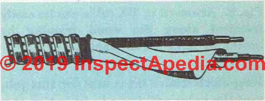
Fig. 4. Section of armored cable showing anti-short bushing in place and heavy paper over wires.
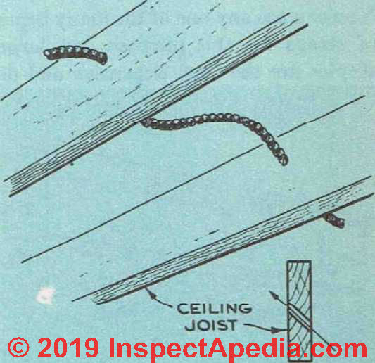
Fig. 5. How BX cable can he run through studding and joists.
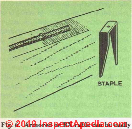
Fig. 6. Armored or BX cable can be easily installed along the wood framing by means of large metal staples.
A long electrician’s bit is best for this job, and the holes will have to be cut in at a slight angle. See Fig. 5. Drill the holes at the approximate center of the studding and joists. The cable should be supported every 4 feet or so and at not more than 12 inches from each outlet. You can use any one of the many types of straps for this purpose, but large staples are the least expensive and do
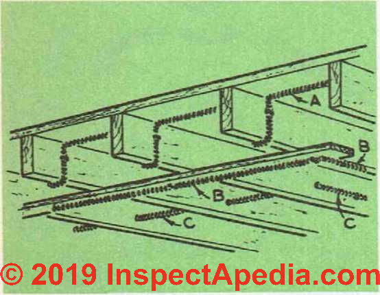
Fig. 7. Three methods of running cable over a ceiling.
not require more than a moment to install. See Fig. 6.
Fig. 7 shows three methods of running a cable across a ceiling. Note that in B, where the cable is unprotected, a running board is used to provide it with adequate support and protection. These running boards should always be used when cables are run across attic floor joists where no flooring is to be used.
Armored cable can be cut w^ith an ordinary hacksaw, but there is a trick in j ust how to cut the material to get a clean break. Hold the saw so that the blade cuts through the strip of armor that runs around the cable. See Fig. 8. Cut through the steel strip but do not cut so deep that the saw damages the kraft paper or insulation over the individual wires.
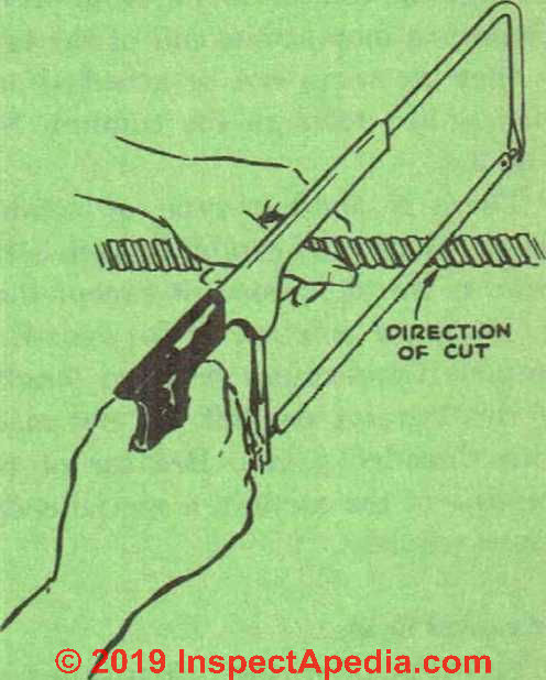
Fig. 8. Correct angle at which to hold the hacksaw when cutting BX cable.
Now take hold of the two ends of the armor and twist the cable apart at the point cut by the saw. Once the armor has been separated, the wires inside can be cut with a pair of snips. N ext, make a second cut about 6 inches from the end of the cable.
Twist off the 6 inches of armor and kraft paper, leaving 6 inches of wire exposed for making connections. Cutting the cable will invariably leave a series of sharp burrs on the end of the armor and these can easily damage the insulation on the wires.
To prevent this possibility, a small fiber anti-short bushing should be inserted at the end of the cable to protect the wires from the burrs. See Fig. 9. The kraft paper covering should be removed from the wire for a short distance underneath the armor, so that this bushing can be inserted into the cable.
Armored cable is attached mechanically to the outlet boxes bv means of special fittings. See Figs. 10, 11 and 12. It is important that a good mechanical connection be made, not only because it will prevent the possibility of any strain being carried by the individual wires, but also because it provides the system with a continuous ground.
A metal connector is slipped over the end of the cable and secured there by tightening a screw. One end of this fitting is threaded and is slipped through one of the knockout holes in the outlet box. A locknut is then placed inside the box over the fitting and tightened by means of a screwdriver. See Fig. 13.
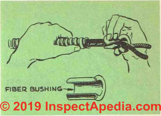
Fig. 9. A fiber anti-short bushing should be placed over the wires to protect their insulation from the rough ends of the metal cable.

Fig. 10 -left. A type of connector used to secure cable to outlet box.
Fig. 11 -center. Cable outlet box connector.
Fig. 12 -right. Cable outlet box connector. This type of connector is secured to the cable by tightening up the screw at the side.
Some types of outlet boxes are provided with built in clamps, which take the place of the separate connectors for the cable.
Armored cable should not be used in damp locations unless it is a leaded type, that is, one that has a lead sheath inside the armor. Use NMC or non-metallic cable, plastic covered wire rated for damp locations instead.
Nonmetallic Sheathed Cable
This type of wiring is somewhat similar to armored cable except that instead of a covering of steel the wires are protected by a heavy fabric that is treated so that it is fire and moisture resistant. See Fig. 14. It should not, however, be used for outside work or in damp locations.
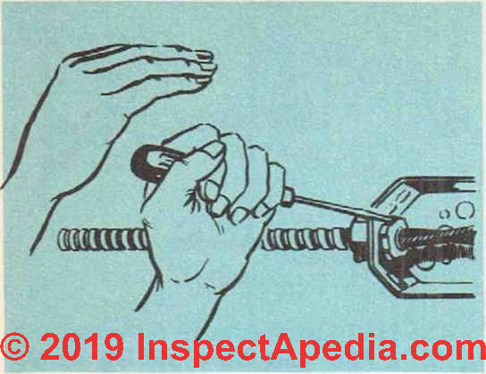
Fig. 13. Armored cable is secured to the outlet box by means of a lock nut, which can be tightened with a screwdriver.
This particular type of wiring is very popular wherever it is permitted by codes. It is less expensive than the rigid steel conduit or armored cable and is very easy to work with.
For the most part, nonmetallic sheathed cable is installed in the same manner as armored cable. Metal straps, rather than large staples, should be used to fasten the cable to woodwork. See Fig. 15. Staples are not satisfactory because of the possibility that their sharp points may damage the cable’s fiber or plastic or rubber covering.

Fig. 15. Metal bracket used to support nonmetallic sheathed cable. Metal staples should not be used on this type of wire.
The cable should be supported every 4 feet or so and 12 inches from each outlet box.
The outer covering of this type of wire can be removed by slitting it with a knife and then ripping it back as far as desired—at least 6 inches when connections are to be made. The ends of the insulation can then be cut off with a jacknife. Be careful not to damage any of the insulation around the individual wires when cutting off the outer insulation.
Nonmetallic cable can be fastened to an outlet box with a type of fitting similar to that used with armored cable. The connector is first attached securely to the cable and then inserted in the box. A locknut is then run up to secure the connection.

Fig. 14. Nonmetallic sheathed cable.
One type of nonmetallic cable has a insulated wire should be attached to the third wire—an uninsulated wire—for frame of the outlet box. In this way the grounding purposes. If the local code entire system is grounded through the requires this method of wiring, the un- ground wires connected to the boxes.
Electrical Wire Size
The size of wire required for the various circuits throughout the house will depend in each case on the circuit.
There are three different kinds of circuit. The first is the general purpose branch circuit. This requires a 15 ampere fuse and the wire size is No. 14.
The maximum safe load for this circuit is 1725 watts, a figure arrived at by multiplying amperes (15) by volts (115). This type of circuit is used for lighting, and the like.
The second type of circuit is the appliance branch circuit. It is fused with a 20 ampere fuse and the wire should be No. 12. It has a safe load of 2800 watts and is required for the various electrical appliances used in the kitchen, dining room, workshop, etc. These appliance branch circuits should not be used for lighting purposes—they are for appliances only.
The third type of circuit is the individual branch circuit and here the wire size will vary depending on the particular piece of equipment it serves. Each individual branch circuit serves one piece of equipment only. Fuel-fired heating equipment, electric garbage-disposal units, automatic washing machines, home freeze units, water pumps, and power equipment for the home workshop should all have individual 20 ampere, No. 12 wire branch circuits.
Heavier equipment such as electric kitchen ranges or electric clothes dryers will require even heavier wiring. Kitchen ranges usually require a No. 6 wire and a 50 ampere fuse on a three wire 115/230 volt system.
See details at WIRE SIZE for SERVICE ENTRY vs AMPS
Number of Electrical Circuits Required
As a general rule, there should be one general purpose branch circuit for every 500 square feet of finished floor area or fraction thereof. All these circuits are of No. 14 wire with 15 ampere fuses. In addition to this, there should be at least two appliance branch circuits for the kitchen, for the workshop, and so on. These require No. 12 wire.
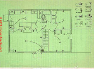
After these come any individual branch circuits that may be required. Fig. 16 shows the wiring diagram for the basic house. It contains 3 general purpose branch circuits, 2 appliance branch circuits and 3 individual branch circuits.
Adequate electrical wiring should not only contain a sufficient number of circuits to meet present requirements but should also provide for expansion of the house or an increase in various types of electrical equipment.
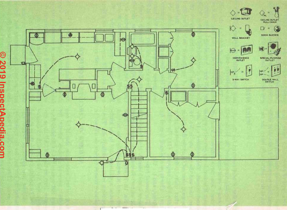
Fig. 16. Wiring diagram for house.
It is a lot simpler to put in additional circuits for future needs when the main wiring is being done than to have to do this work at a later date when the walls and ceilings have been finished and wires have to be run in back of the walls and fished out through openings.
Steps in Wiring the House
The Service Entrance
The first step in wiring the house is to locate the position of the service entrance. This is the point where the power is brought into the house and its exact location will depend on the location of power lines. The local power company should be consulted in this matter. The service entrance will include the wires that bring the power into the house as well as the meter and service switch.
The meter and switch can be placed indoors, but there is a definite advantage in having the meter outside which is that this allows the meter to be read without disturbing the household. Also, if there is no basement, it is just one less piece of equipment that you have to find wall space for.
Service insulators must be installed on the outside of the house, where they serve as a base for the power lines running to the house. See Fig. 17. Three of these insulators will be required, and they can be installed individually or as a unit. The insulators must be placed at least 6 inches apart and must be solidly attached to the building. They should be placed as high on the building as possible.
If the power lines have to cross a road or driveway, there is usually a regulation in the local code that states just how far off the ground they must be. In the event that there is no regulation in the local code, be sure to keep the insulator at least 18 feet off the ground. The power lines are attached to these insulators and the service cable that brings the power into the house is spliced to them.
The service wires should be No. 4 (or more likely by 2019 standards, No. 0 or larger).
For details see this article: WIRE SIZE for SERVICE ENTRY vs AMPS,
You will require 3 of them. They can be run through conduit or you can use special service-entrance cable that does not require a conduit. If the service wires are to be run underground, a lead-sheathed cable is used that is run through a conduit.
Where the service wires leave the conduit or cable in order to be attached to the power lines, a special type of fitting is required so that moisture will not get into the cable or conduit. This fitting is called a service head. When rigid conduit is used still another special fitting is required at the point where the wires enter the building. See Figs. 18 and 19.
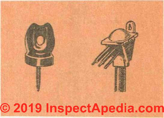
Fig. 18. A service head for a service entrance cable.

Fig. 19. Service head for service entrance conduit - left. & Fig. 20. Type of fitting used at bottom of conduit to bring entrance cable into building - right.
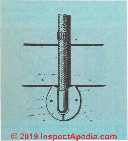
Fig. 21. Sill plate used to bring service entrance cable into building.
A similar type of service head (Figs. 20 and 21) is required for service cable where it enters the building to prevent moisture from following the wires indoors. Rigid conduit is attached to the side of the building by means of metal straps. The cable is attached with special clips containing screws.
If an outdoor meter is used and the service wires are run in rigid conduit, the conduit is mechanically attached to the meter box. This will produce a weathertight joint. In the case of entrance cable, a special waterproof type of fitting is used to make the joint between cable and meter box watertight.
Main Switch and Fuse Box
From the electric meter, the service cable runs to the main switch and fuse box. In old installations there was usually one piece of equipment containing the main fuses and main switch and another containing the various circuit fuses. Today there are a great many pieces of equipment that combine all these various operations in one small compact box.
The switch and fuse box should be located where it is readily accessible. If there is a basement in the home, it is the usual location for this equipment, but the basement is not necessarily the best location. It may be much more convenient to have the equipment where you can get to it easily when a fuse blows— not having to locate a flashlight and stumble down to the basement. The kitchen and the utility room are both good spots to locate the switch and fuse
box. The box, recessed into the wall and with a hinged door, can, in fact, be located in any room of the house— wherever it is most convenient and still near the service entrance.
The type of service switch and fuse box to use will depend upon your pocket book and the local codes as well as on the location of the equipment. If you plan to have it recessed into one of the room walls, you want something that is compact and takes up no more room than is necessary.
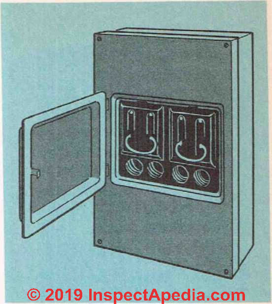
Fig. 22. A pull-out type of main switch and fuse box. Most modern homes (2019) use a circuit breaker panel and a main circuit breaker to control all power to the building.
Fig. 22 shows a pull-out type of switch and fuse box. The main fuses are held in clips mounted on plastic blocks. There is no over-all main switch, but when the blocks are pulled out of the cabinet by means of their handles, the power to the house circuits is cut off. This fuse panel would be inadequate for most homes in 2019.
Fuses for the house circuits are located under the main fuses.
Fig. 23 shows another type of switch and fuse box. In this piece of equipment, when the door of the box is opened the current is automatically cut off. It also contains fuses for the house circuits.
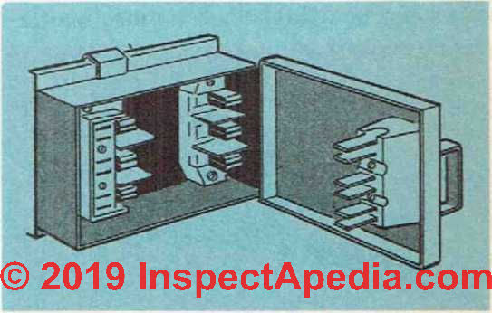
Fig. 23. The switch in this type of switch and fuse box is operated by opening and closing the switch-box door. When the door is open the house circuits are broken.
Circuit Breakers
Another type of equipment is the circuit breaker.
This unit does not contain the orthodox type of fuse. When there is an overload or a short circuit, the mechanism inside the circuit breaker automatically breaks the flow of cur-rent and cannot be set back until the cause of the trouble has been removed. The main switch mechanism inside the box is operated by a small mechanical switch. See Fig. 24.
The great advantage that the circuit breaker has over the ordinary type of fuse box is that when there is a short circuit, you do not have to worry about whether or not there is an extra fuse around to replace the one that has blown. Once the cause of the trouble has been corrected, the circuit breaker can be reset. [In 1950 Some local codes did not permit circuit breakers.]
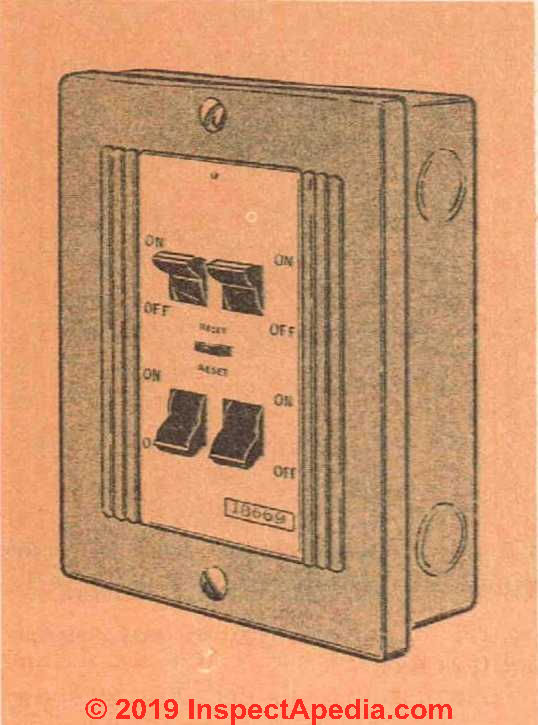
Fig. 24. Circuit breaker.
All connections on the service entrance equipment must be of the solderless type. See Fig. 25. Lugs are provided in the units so that the various wires can be attached. No more insulation should be removed than is necessary to make a good connection— electrically as well as mechanically. Be sure to clean the wires at the point of contact so that no insulation is left on them.
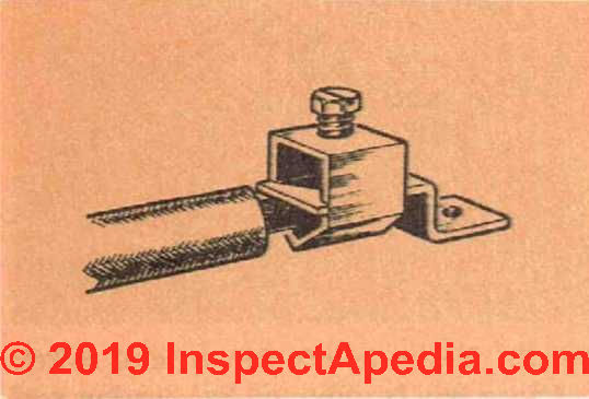
Fig. 25. Lug used for making connections at the service entrance and inside fuse panels or circuit breaker panels.
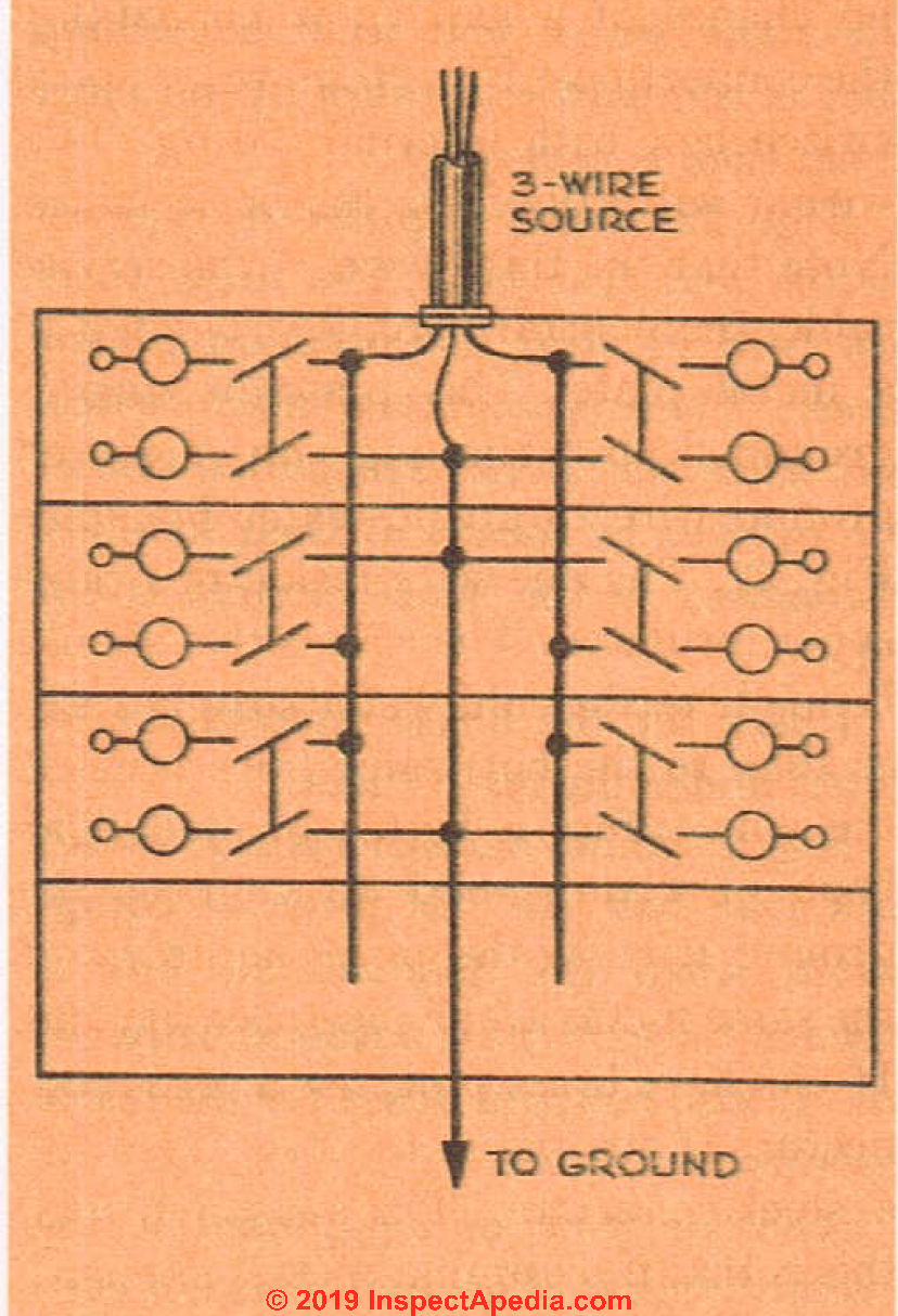
Fig. 26. Internal wiring for typical switch box. Note that no soldered connections are used inside the switch box. Also note the ground wire from the switch box which is connected to the house plumbing system.

Fig. 27. A single uninsulated wire in an armored cable is used to ground the house electrical system.
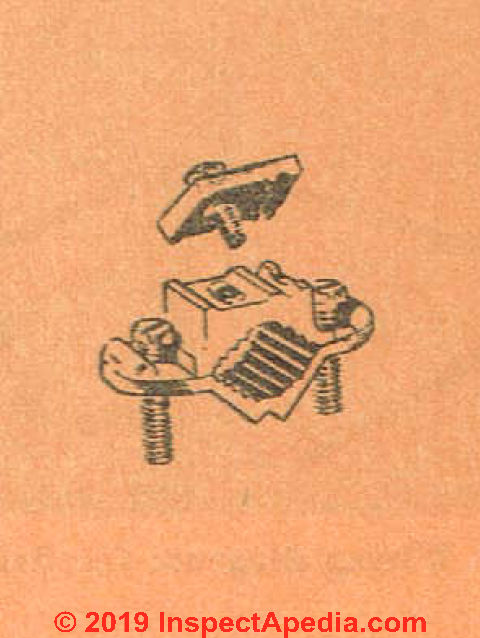
Fig. 28. Ground clamp used to secure ground wire io plumbing line.
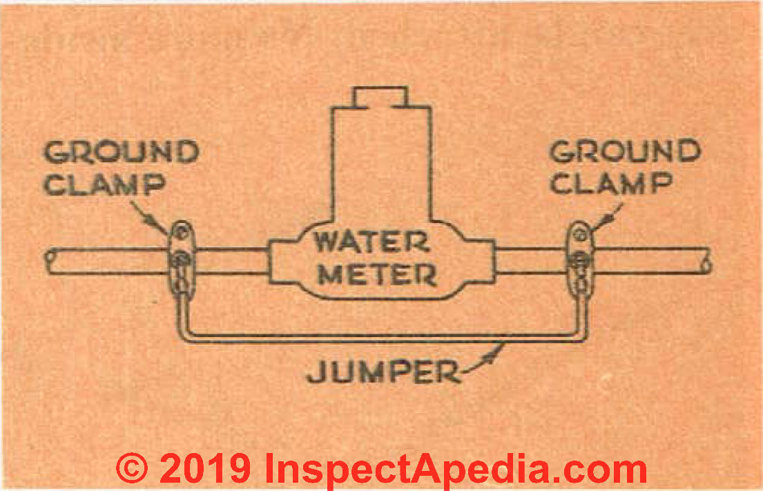
Fig. 29. If the house has a water meter, a wire jumper should be put around it so that if the meter is removed, the electrical system will remain grounded.
Service switches and fuse boxes usually have an internal wiring diagram attached to them so that there will be no chance of a slip-up when making the connections. Fig. 26 shows a typical switch box with internal wiring. This wiring will apply for the basic house. Note that the third wire of the service cable, the neutral wire, is grounded to a metal plate. This plate in turn is grounded by running an armored ground wire to a cold-water line.
See Fig. 27.
The one wire inside this cable is not insulated. The connection should be made to the cold-water supply rather than to the hot-water lines because the cold offers a better ground. The type of clamp used to connect the ground wire to the pipe should be of the same metal as the pipe.
See Fig. 28.
If you have brass pipe, use a brass connector. If the pipes are steel, then use a steel connector. The reason for all this is that if dissimilar metals are used, you will get an electrolytic action between the metals that will prevent an adequate ground.
In case you make the ground on the house side of the water meter, there should be an electrical connection made around the meter. This is necessary because if the meter should be removed for one reason or another, you will still want your electrical system and it must be adequately grounded. Fig. 29 shows the type of hook-up used for this purpose.
In 1950, if you grounded the wires on the far side of the meter, this procedure was considered not necessary. But currently (2019) the jumper around the meter is needed for a second important safety reason: to assure that the house plumbing is also grounded - that keeps you from being electrocuted if you knock a toaster into the sink. For important electrical code and safety details see the GROUNDING article links at the end of this chapter.
The rating of the service equipment will depend on the number of circuits and the load required. For our purpose [in 1950], the switch should be rated at 100 amperes and the main fuse or breaker at 70 amperes. Current practice will provide at least 100A to the home, often larger depending on what electrical equipment will be installed; the main breaker will typically be 100A or larger as well.
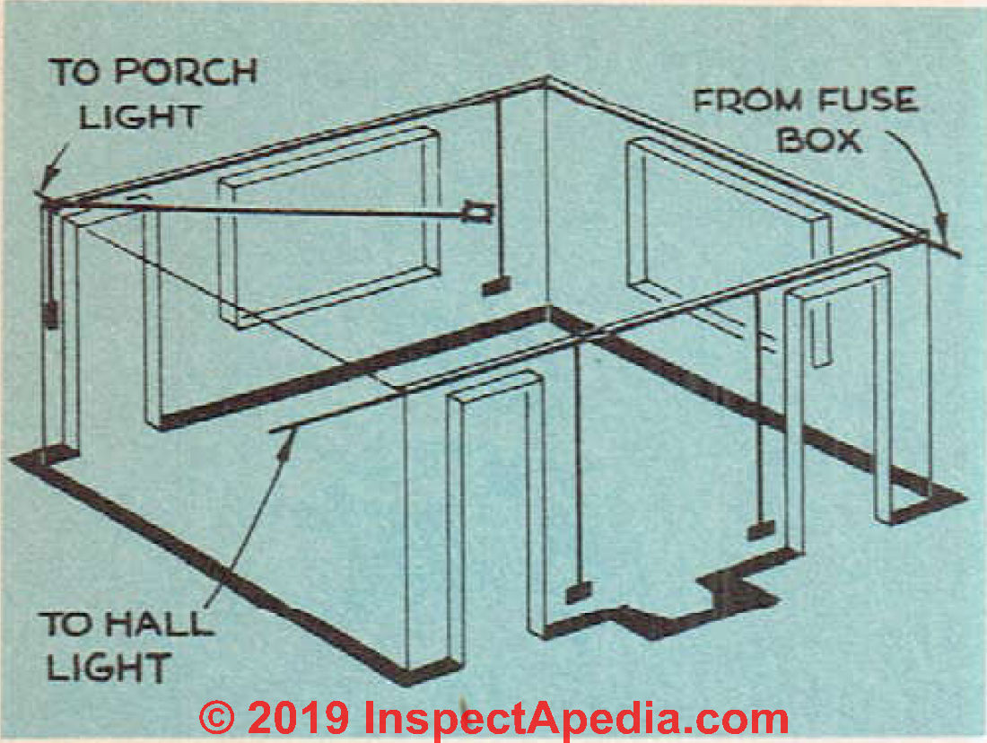
Fig. 30. Wiring diagram for living room.
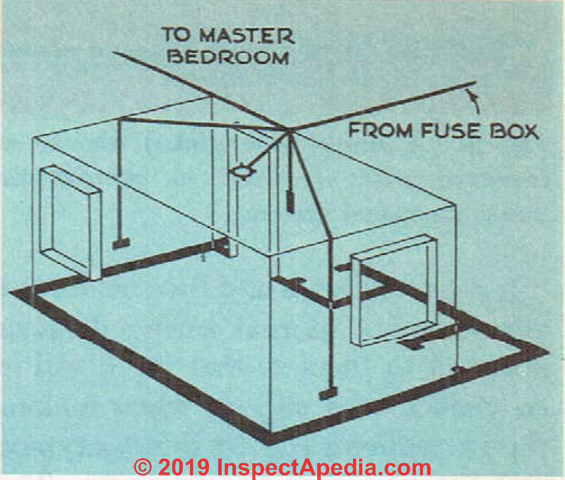
Fig. 32. The wiring diagram for small bedroom.
If a circuit breaker is used, it should have a 70 ampere rating.
The next project is to install the various outlet, switch and junction boxes. Figs. 30. 31, 32, 33 and 34 show approximate locations for these boxes in the various rooms. The solid lines are general branch circuits that are rated at 15 amperes and made of No. 14 wire. The dotted lines are 20 ampere appliance circuits made with No. 12
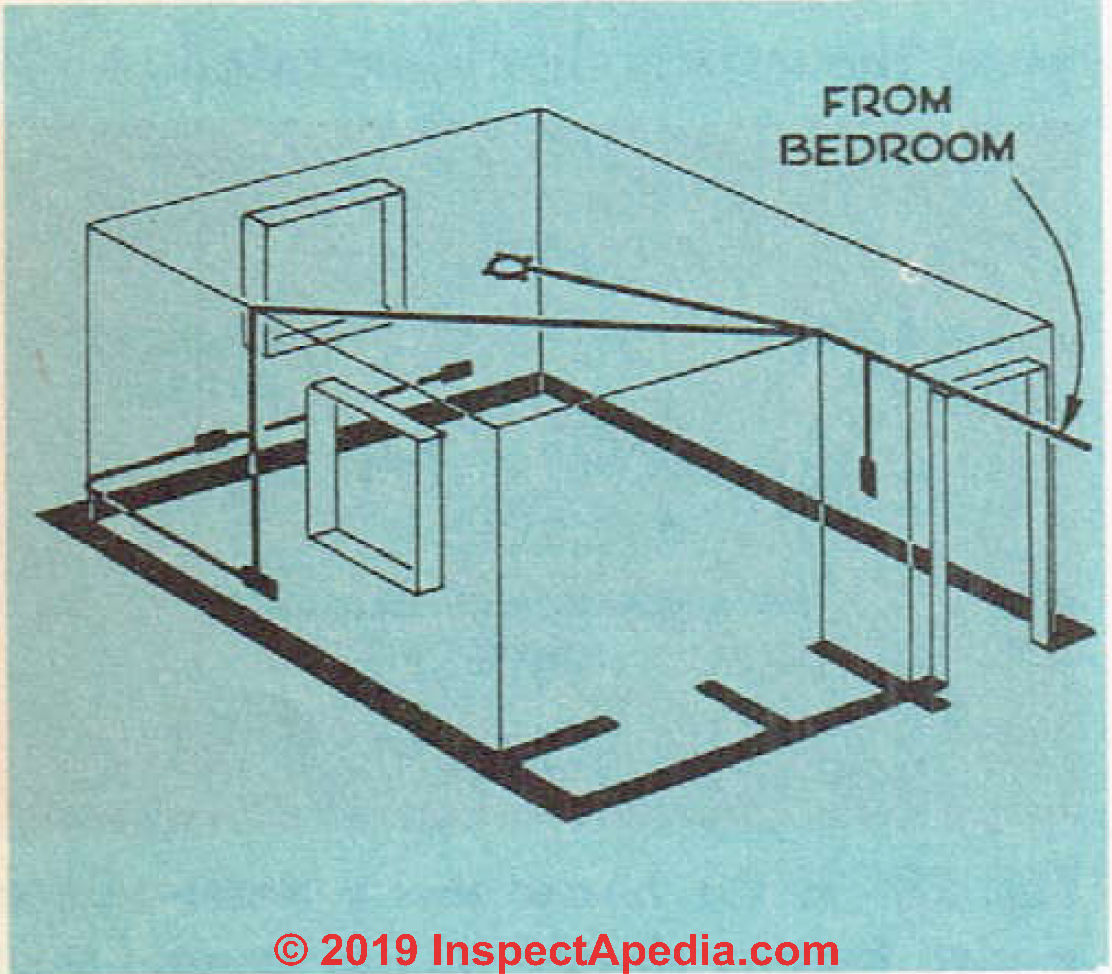
Fig. 31. The wiring diagram for master bedroom.
wire. Shaded lines are individual circuits.
Installing Electrical Outlet Boxes (Receptacles)
Metal outlet, switch and junction boxes serve several purposes. See Fig. 35. First, they provide a base for mounting fixtures or switches. Second, they provide a means of splicing wires. No splices should be made, under any circumstances, except in boxes.
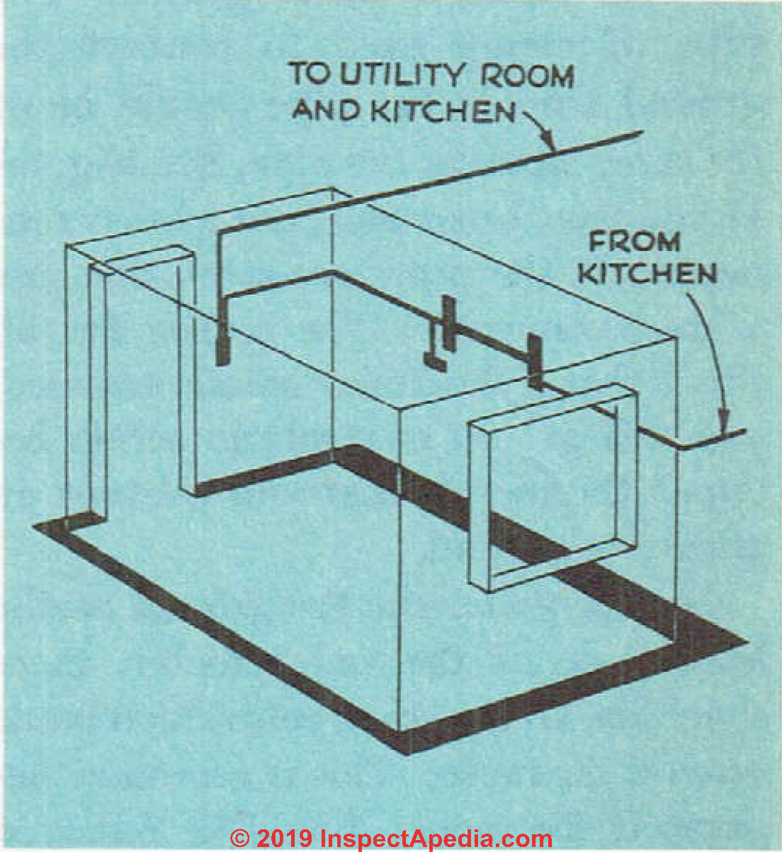
Fig. 33. Wiring diagram for bathroom.
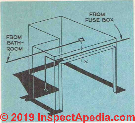
Fig. 34. Wiring diagram for utility room.
The reason for this is that there is usually enough inflammable matter, such as dust or sawdust, in back of a wall or ceiling to start a fire if there should be a short-circuit spark in the wiring.
These metal boxes can be had with brackets attached to them so that they can be attached to the studding or joists. Some types have small nietal lips suitable for the same purpose. See Fig. 36. When a box must be placed between tw'o pieces of studding or joists, metal hangers can be used or the opening can be framed with odd bits of studding. See Figs. 37 and 38.
The various boxes are provided with several little round knockouts, which can be removed so that the wires can be brought into the box. See Fig. 39.
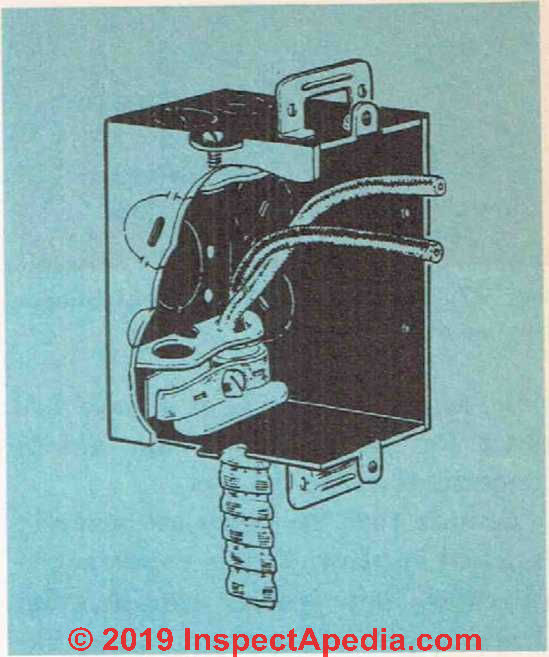
Fig. 35. Outlet box showing clamps used to secure the cable to the box.
Just give the circular piece of metal a sharp jab with a heavy screwdriver and it can then be easily removed. Do not remove any more of these knockouts than there are wires entering the box. Each box has a metal face-plate, which must be replaced after all the connections have been made.
You will find that it is better to use the larger sizes of boxes whenever possible, as they will make it a good deal easier for you to handle the various connections inside the box.
Details are at ELECTRICAL BOX TYPES
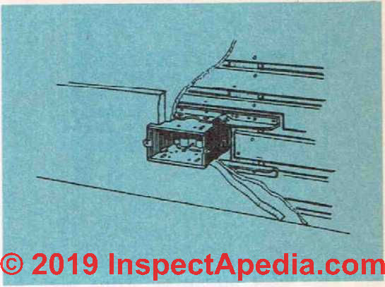
Fig. 36. Outlet box with metal bracket for fastening to wall studding.
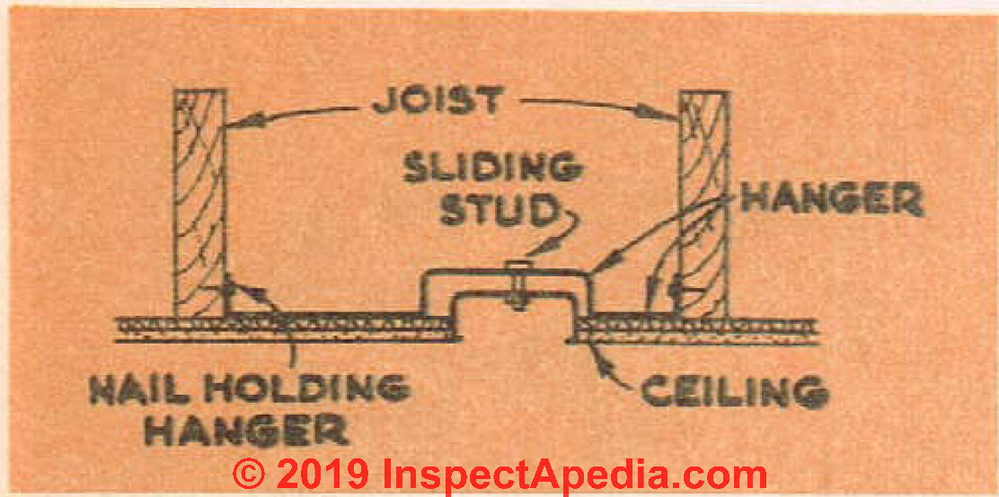
Fig. 37. Outlet box with built-in hanger for use on ceilings.
Be sure that the boxes are securely fastened in place. This is important in all cases, but special consideration should be given to wall and ceiling fixtures where the entire weight of a rather heavv fixture will be carried bv the outlet box.
Do not forget to allow for the thickness of the plaster or wall-board that is going to make the interior walls.
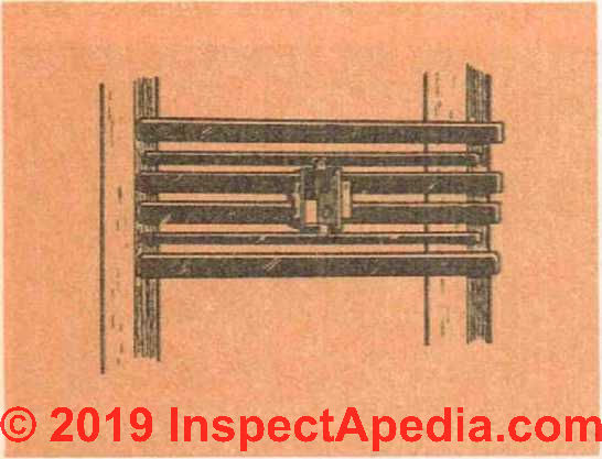
Fig. 38. Steel mounting strips used to fasten outlet box between wall studding or ceiling joists.
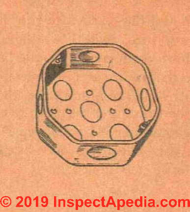
Fig. 39. Outlet box showing knock-outs.
No matter what type of wiring method is used, it is most important that there is a strong mechanical connection between the conduit or cable and the box. Allow the wires to extend into the box for about 6 inches, as this much free wire will be required for making connections.
Black and White Wire
One of the wires used in wiring is covered with black insulation - the "hot" or "live" wire. The other is covered with white or grey insulation - the neutral wire - sometimes the neutral wire has a white tracer instead of a solid color.
The black wire is always the “hot” wire and the white wire is always the neutral wire. When the wires are connected to the fuse box, the black wire should be connected so that the current to it is broken bv the fuse. The white wire is connected to the metal neutral-strip, which is grounded.
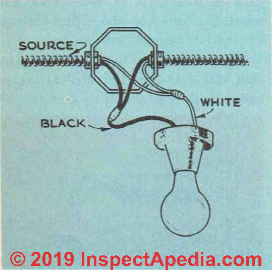
Throughout the entire wiring system, this difference between the two wires must be respected. The black wire is always broken by a switch, the white one never. See Fig. 40.
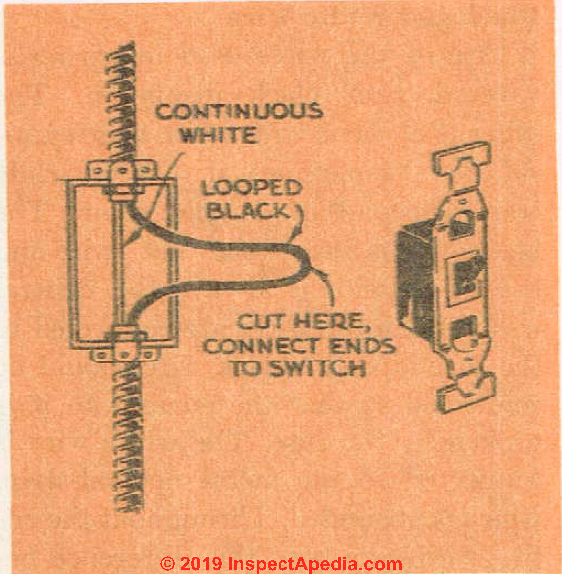
Fig. 40. When a switch is installed, it should always be wired through the black wire rather than the white wire
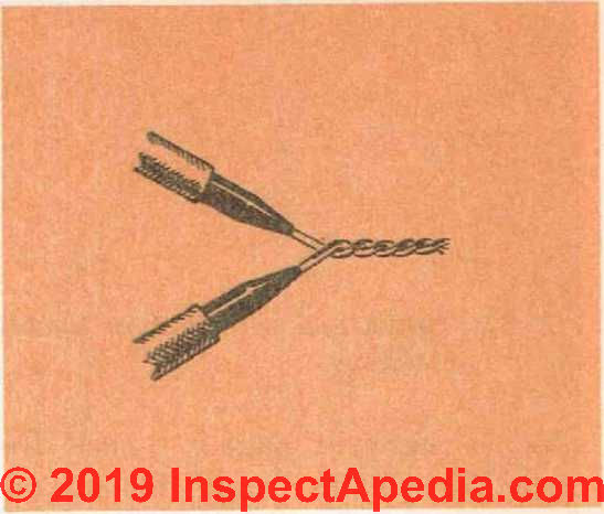
Fig. 41. A pigtail splice. The wires should l>e soldered and then covered with rubber insulation tape as well as friction tape.
The reason for this is that if the white wire were to be broken by the switch and the black wire run directly to the fixture, then, even though the switch were off, current would be flowing to the fixture and if someone were to touch it and be grounded at the same time, he would get a shock. The black wire should never be connected to the white wire except in one special circumstance, mentioned later.
Three-Wire Cable for 3-way Switches
Cable containing three wires—black, white and red—should be used on all three-way switches, that is, when a fixture is to be controlled by two switches at different locations. While not absolutely necessary, three-wire cable should also be used for fixtures controlled by wall switches since this will eliminate an extra run of cable.
From the main fuse box, the various circuits run to the portion of the house that they serve. If there is a basement in the house, the logical place to run these sub-feeders is along the basement ceiling and then up through the floor into the wall area. If there is no basement, the lines can run either through the wall or along the ceiling.
The best way to insure a wiring job that will pass the most critical inspection is to do it as neatly as you possibly can.

Fig. 42. How wire should be fastened around terminal screw. The wire goes around the screw in the same direction that the screw is turned to tighten.
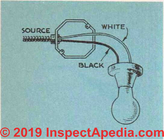
Fig. 43. The simplest type of hook-up. The supply of current to the fixture is controlled by a switch and pull chain built into the fixture.
Be sure that all connections to outlet boxes are secure. When it is necessary to splice a wire—and splices should only occur in metal boxes—use a pigtail splice as shown in Fig. 41.
Remove the insulation from the ends of the wire and then scrape the wire clean with a knife. Twist the wires together and then solder the connection. Lnlike connections in the sendee entrance, connections in the house wiring
should be soldered. You can save yourself a lot of time by making all the connections first and then going around and dipping each one in a small ladle filled with molten solder. This is considerably faster than trying to solder each connection with a soldering iron.
After the connection has been soldered, the exposed wires should be covered with a layer of rubber tape. Over this goes friction tape until the insulation around the splice is at least as thick as the insulation on the rest of the wires.
Fig. 44. When the source is to continue on to another fixture, splices in the wires must be made inside the first fixture outlet box.
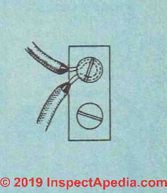
Fig. 45. When a wire continues on to another fixture, it is not necessary to cut it at a terminal screw.
When connecting wires to terminal screws on wall switches or on fixtures, remove only enough insulation to allow the wire to be twisted around the screw’. The wire should go around the terminal screw in the same direction that the screw is turned to be tightened.
See Fig. 42. If the wire goes on in the opposite direction, as the screw is run up it will have a tendency to force the wire away. A pair of long-nosed pliers is a “must” for making tight and neat electrical connections.
The simplest type of wiring that you will run into is that for an outlet with a pull-chain, such as will be required in the basement, closets, etc. Wires running directly from the source are connected to the fixture without any other problem involved. See Fig. 43.
If the wires are to continue on to another outlet, a splice must be made inside the first fixture-outlet box. See Fig. 44.
The same thing applies when wiring to convenience outlets. In this case, however, it is often not necessary to make a splice because the terminal screws on the outlet itself will allow you to make the connection between the two wires here. See Fig. 4.5.
When a fixture is to be controlled by a wall switch, the wiring becomes a little more complex. Fig. 46 shows one method of taking care of this matter.
The cable running from the fixture box to the switch box contains ordinary black and white wire. The white wire of the source cable is attached to the white wire of the fixture.
The black wire of the source cannot be attached to the black wire of the switch cable because this wire is going to have to be attached to the black wire of the fixture.
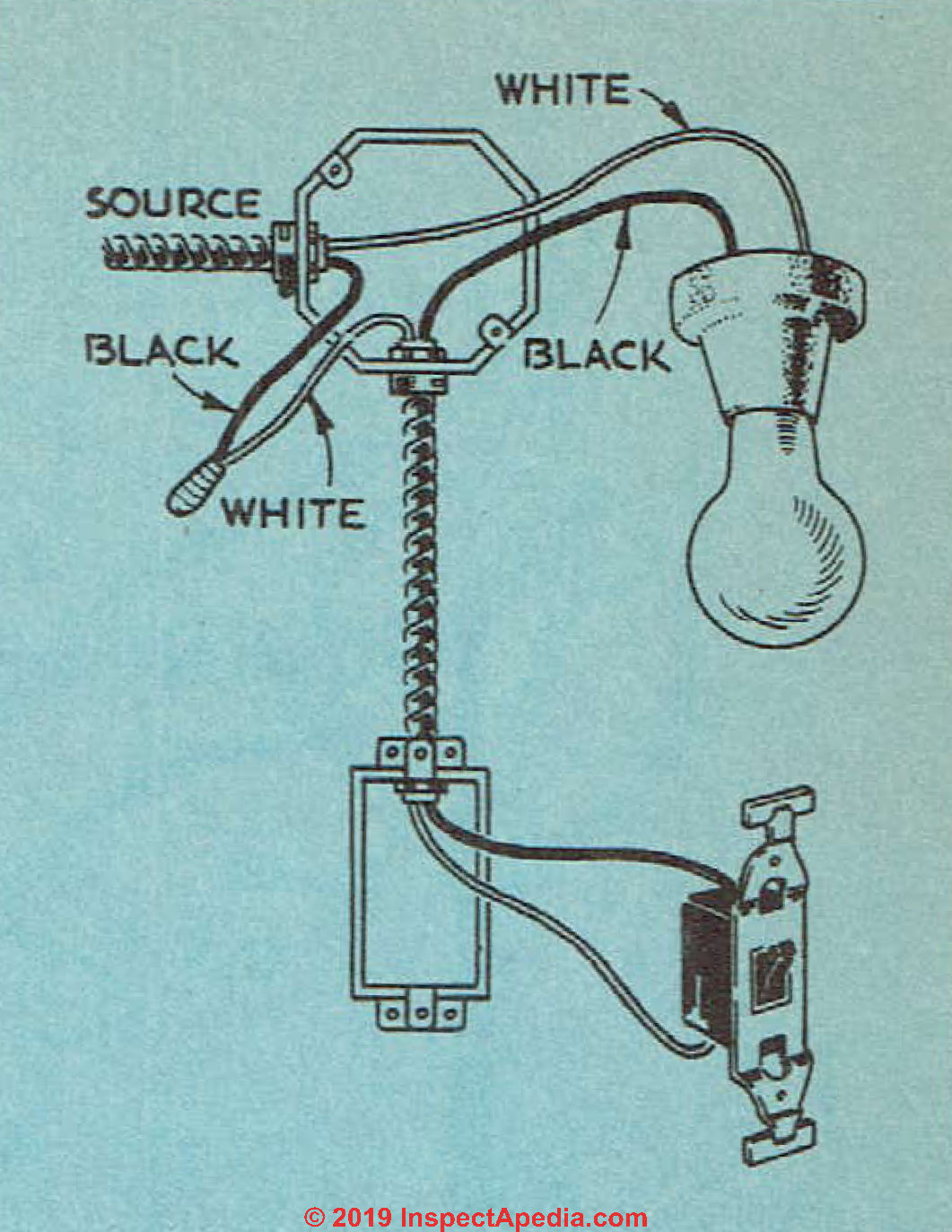
Fig. 46. How a wall switch should be wired to a fixture. Note that because a standard black and white wire cable is used from the fixture to the switch, the black source wire is connected to the white switch wire.
The only thing to do then is to attach the black wire of the source to the white wire of the switch cable. (This is the only case where black wire is attached to white.) Of course, if the location of the source cable is such that it can easily be run through the switch on the wav to the fixture, all this is not necessarv. The connection can be made as showm in Fig. 40.
Another way of wiring in a wall switch so that it will control a fixture but not the one beyond is shown in Fig. 47. Here the source is brought into the switch on a regular two-wire cable.
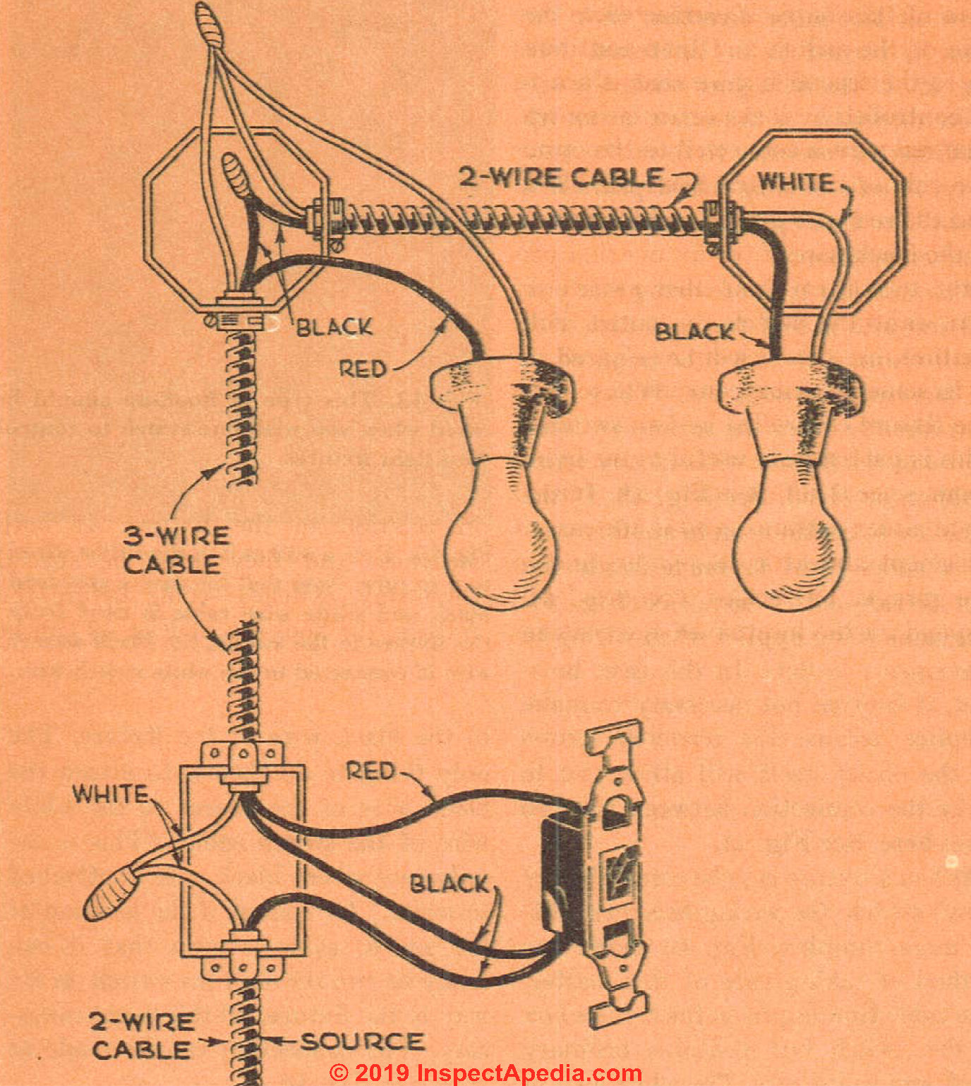
Fig. 47. The above illustrates how a when it is only to control the first and not switch should be wired to two fixtures the second fixture.
The white wire is not run through the switch but is connected to the white wire running to the fixture. The black wire of the source is connected to one side of the switch and then continues on to the second fixture that is not to be controlled by that particular switch. The red wire is connected to the opposite side of the switch from the black, and the red wire is then run to connect to the black wire of the fixture that you want to control from that switch. If you want the switch to control both fixtures, use the hook-up in Fig. 48.
In some cases it is convenient to have one fixture controlled by two switches.
This is particularly useful in the living room, since it allows lights to be turned on at either entrance, and in the case of basement and attic stair-lights and in the garage.
The hook-up required will depend on the location of the switches in relation to the fixture.
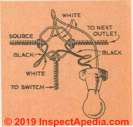
Fig. 48. This type of hook-up should be used when you wish one switch to control two light fixtures.
If both switches—and they must be special three-way switches—come before the fixture, the hook-up in Fig. 49 can be used. If the fixture is between the two switches, then Fig. 50 shows the correct connection. If the source comes into the fixture first, use Figs. 51 and 52.
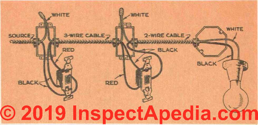
Fig. 49. The above illustration shows the come before the fixture. Three-wire cable hook-up used when source enters one of is needed only between the two switches the three-way switches and both switches and not throughout.
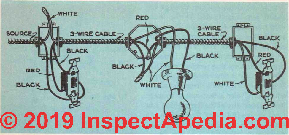
Fig. 50. As depicted above, when the fixture is located between the two three-way switches, three-wire cable must be used throughout.
In some cases it is desirable to wire duplex receptacles so that one half of the outlet can be controlled by a switch while the other half remains permanently connected. The wiring diagram for this hook-up is shown in Fig. 53. Convenience outlets are usually located about 12 inches or so from the sub-floor.
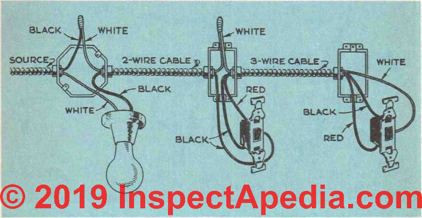
Fig. 51. Hook-up used when the source enters at the fixture but the two three-way switches are located past the fixture on the same side.
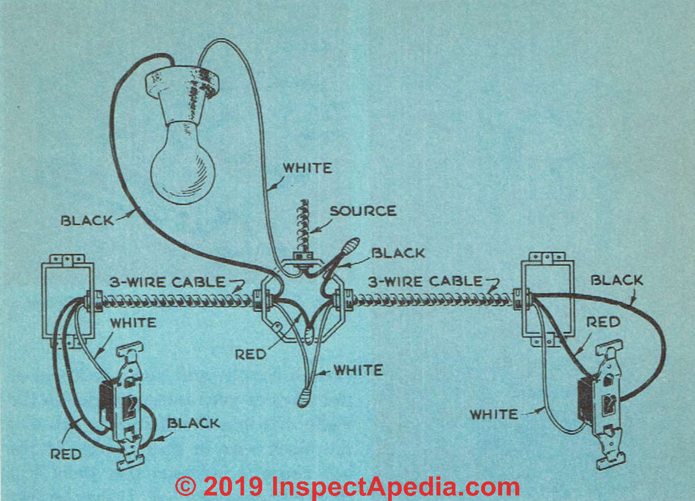
Fig. 52. The above diagram illustrates a three-way switches when the source enters hook-up used to control fixture from two at the fixture.
Wall switches should be about 4 feet from the floor. Appliance outlets in the kitchen should be placed where they will be readily accessible for plugging in various pieces of kitchen equipment, irons, etc.
The final say on this matter should come from the lady or man or person of the house. It is her/his/their kitchen, so put the outlets where that person wants them. A receptacle outlet must be installed for every kitchen and dining area counter wall space 12 inches or wider.
Receptacles must be installed so that no point along the counter wall space is more than 24inches (2 feet), measured horizontally, from a receptacle outlet.
By current (2019) electrical codes, receptacle outlet must be installed for every kitchen and dining area counter wall space 12 inches or wider. Receptacles must be installed so that no point along the counter wall space is more than 24inches (2 feet), measured horizontally, from a receptacle outlet.
A receptacle outlet must be installed for every kitchen and dining area counter wall space 12 inches or wider. Receptacles must be installed so that no point along the counter wall space is more than 24inches (2 feet), measured horizontally, from a receptacle outlet.
The location of these outlets shown in Fig. 54 is only a suggestion.
The location of junction boxes should be such that they can be examined without having to remove any of the wall or ceiling. They should be covered with removable plastic (safer than metal) plates.
Testing the Electrical Wiring
Once the rough wiring has been done, it should be checked over to be sure that it is free of short circuits or any other wiring mistakes. This should be done before switches or outlets are installed and, of course, before the system is connected to the power lines and before the interior wall and ceiling material goes on.
There are special testing devices you can use for this job, but two ordinary dry cells connected in series with a door bell will prove perfectly adequate.
First of all, twist together any wires in the system, such as those in the switch boxes, that would ordinarily be attached together either directly or by means of a switch. Wires that are to be connected to fixtures later on should not be connected—they should be spread apart so that there is no chance of their coming together.
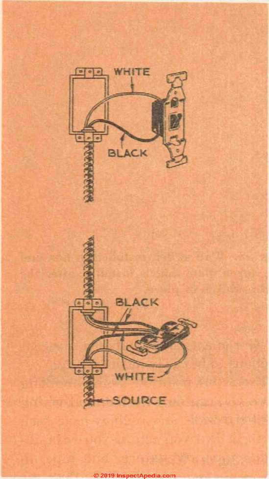
Fig. 53. The switch in this illustration will control one-half of a duplex outlet. This type of connection is very useful in the living room or bedroom when there are no wall or ceiling fixtures.
The first part of the test is made at the switch box. Insert fuses for the various circuits and then touch one of the wires of your testing device to the white wire in a circuit and the other to the black wire in that circuit.
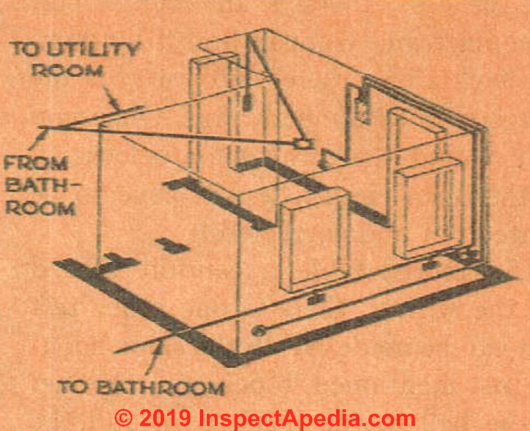
Fig. 54. Wiring diagram for kitchen.
If the bell rings, it indicates that there is a short circuit somewhere. It may be that the black and white wires are touching each other somewhere in the system or, if you are using flexible armored cable or steel conduit, that a black wire is touching the metal of the conduit, cable or metal box. Each circuit should be checked through in this manner.
The next check is made by removing the bell from the batteries and connecting one wire from the battery to the white wire, and the other to the black wire. Now take the bell and go around and connect it to the black and white wires of the various outlets.
If all is well, the bell will ring.
If it does not, go back and check first any wall switch outlets in that particular circuit. It may be that the wires you twisted together are not making a good contact. If this is not the case, there is an open circuit someplace and you can find it by moving back along the circuit towards the fuse box until the bell rings. Once you have found the approximate location of the open circuit, it will have to be hunted out and corrected.
If armored cable or conduit is used for the wiring, there is one other test that can be made. With the same hookup just mentioned, touch one terminal of the bell to the black wire and the other to the metal box. If the bell rings, it means that the system is adequately grounded.
If it fails to ring, it means that at some point in the system you do not have a good mechanical connection between the armor cable or conduit and the box. This test is not used on non-metallic sheathed cable unless it has a ground wire, because with the two-wire cable, you do not have any connection between the various boxes.
As soon as you have your sjrstem checked out, you can go ahead and wire in the switches and outlets. Ceiling and wall fixtures cannot be attached to the outlet boxes until the ceiling and walls themselves have been completed, but be sure that there is a sufficient amount of wire in each box to allow these connections to be easily made.
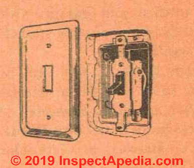
Fig. 55. Wall switch installed in box and the cover plate that is installed after the finish wall is in place.
From this point on there is nothing more you can do with the final wiring until the walls and ceilings have been finished. But you can, if you wish, in-stall temporary fixtures and tape up any wires not required so that the power can be connected into the house and you will have adequate lighting for interior work as well as having power for machine tools.
Finishing the Electrical Wiring Installation
Wlien the walls and ceilings have been finished, Ihe last step in the house wiring can be completed. This will include mounting and attaching the various fixtures, in addition to installing plates over switches, outlets, etc. See Fig. 55.
Electric fixtures are of standard design and every brand is equipped with some sort of device so that it can be attached to an outlet box.
Fixtures used in damp locations should be of porcelain rather than metal as this reduces the shock hazard. For ordinary purposes, this type of fixture should be used in the basement, bathroom, kitchen and garage. Outdoor fixtures should be of some special type that is weathertight.
Certain types of wall and ceiling fixtures have two wires attached to them that are to be connected to the two wires in the outlet box.
White wire should be attached to white, black to black. All connections should be pigtail splices, soldered and taped.
If there are no wires on the fixture, the outlet wires can be attached to it with the terminal screws. The white wire should be attached to the white (or silver colored) terminal screw, the black wire to the bronze or gold screw. Wall switches and convenience outlets are attached to the wires by means of terminal screws on the body of the switch or outlet.
Do not allow a fixture to be hung so that only the wires support it. It must be solidly attached to the outlet box.
You will find when fastening wall switches in place, that the holes on the outlet box are elongated so that even if the box is not quite straight, it is still possible to position the switch itself so that it sits plumb.
Kitchen Electric Range Wiring
Wiring for kitchen ranges differs from the ordinary house wiring in that a three-wire system is used instead of a two-wire system. Ranges operate on 115/230 volts, while the rest of the house system operates on 115 volts and a two-wire system.
The reason for the three-wire system for ranges is to provide the necessary span of temperature control. When the range is turned up as high as it will go, it operates on 230 volts. When cut down low, it operates on 115 volts.
Many persons are confused as to just what volts and amperes are. Such confusion can cause a good deal of trouble when it comes to installing electrical equipment. Volt is a term used to indicate the electrical pressure in a line. It does not indicate how much current is actually flowing through the line. The unit used to measure the actual flow is the ampere.
The practice today is to bring a three-wire 115/230-volt system into the house when the service entrance is installed. This eliminates the need for doing any great amount of extra wiring if you should decide to install an electric range at some later date.
Most of the electrical equipment on the market today is made to operate on a 115-volt system. If this equipment were to be wired directly into a 230-volt system, the pressure of the current in the lines would be too great and the appliance would be ruined.
Ranges rated above 12 kilowatts should be fused with a 50-ampere fuse to take care of the heavy flow of current required by such appliances. The wiring from the switch box to the range must also be heavy enough to carry the current without the wire’s overheating and burning up the insulation.
When a 50-ampere fuse is used, a No. 6 wire is suitable. The type of wiring can be the same as that used for the house electrical system. BX cable, non-metallic sheathed cable and conduit are all suitable.
The electric range cannot be wired directly to the house system but must be wired through a plug that provides a means of disconnecting it from the system. This plug is a heavy-duty three-wire receptacle. It must have a rating in amperes adequate for serving the equipment, as must the wiring and the fuse. The receptacle is usually placed in back of the range so the range can be plugged right into it.
The frame of the range must be grounded. This is accomplished either by an independent ground or by connecting the frame right to the neutral wire.
Materials List For Electrical Equipment For The Basic House - 1950 Standards
- 1 3-wire service entrance cable (length depends on location)
- 1 Service entrance head
- 1 Service entrance ell or sill plate
- 1 Switch and fuse box or circuit breaker panel
- 1 Grounding bushing
- 1 No. 6 wire ground cable (length of run from fuse box to water pipe)
- 30 4" or 3 1/4" outlet boxes
- 29 2 1/2"-deep switch boxes
- 100 Cable connectors 100 Fiber bushings (for flexible armored cable only)
- 7 Ceiling fixtures
- 2 Ceiling fixtures with pull chain
- 2 Wall fixtures
- 1 Outside wall fixture
- 6 Single wall switches
- 2 Double wall switches
- 2 3-way switches
- 14 Duplex convenience outlets
- 3 Special purpose outlets 12 Wall-switch plates
- 14 Duplex convenience plates 3 Special purpose outlet plates 9 Offset metal hangers for ceiling fixtures
- 350 feet (approximately) of No. 14 two cable - (hot, neutral+ ground) DO NOT USE UN-GROUNDED Cable in New Wiring (2019 Standards)
- 50 feet (approximately) of No. 14 three-wire cable
- 50 feet (approximately) of No. 12 two-wire cable
- 2 Door bells and buttons
...
Continue reading at HEATING SYSTEM CHOICES for YOUR HOME - next chapter in this book, or go to book contents at BUILD YOUR DREAM HOME, or select a topic from the closely-related articles below, or see the complete ARTICLE INDEX.
Or see these
Recommended Articles
- BUILD YOUR DREAM HOME
- CEILING LIGHT FIXTURE INSTALLATION
- ELECTRICAL BOX TYPES
- ELECTRICAL BOX GROUND WIRING
- ELECTRICAL CODE BASICS
- ELECTRICAL DEFINITIONS
- ELECTRICAL DISTRIBUTION PANELS
- ELECTRICAL GROUNDING in OLD HOUSES
- ELECTRICAL INSPECTION, DIAGNOSIS, REPAIR - home
- ELECTRIC METERS & METER BASES
- ELECTRICAL OUTLET, HOW TO ADD & WIRE - home
- ELECTRICAL SERVICE ENTRY WIRING - home
- ELECTRICAL SPLICE WIRING DETAILS
- ELECTRICAL TOOLS BASIC
- ELECTRICAL WIRE CLEARANCE FROM DUCTS & PIPES
- ELECTRICAL WIRING BASICS
- LIGHT SWITCH WIRING DETAILS
- SERVICE ENTRY WIRING & AMPACITY - home
- VOLTS or VOLTAGE
- WIRE SIZE for SERVICE ENTRY vs AMPS
- WIRE SIZE REQUIRED for ELECTRICAL RECEPTACLES
Suggested citation for this web page
ELECTRICAL WIRING INSTALLATION BASICS at InspectApedia.com - online encyclopedia of building & environmental inspection, testing, diagnosis, repair, & problem prevention advice.
Or see this
INDEX to RELATED ARTICLES: ARTICLE INDEX to BUILDING ARCHITECTURE
Or use the SEARCH BOX found below to Ask a Question or Search InspectApedia
Or see
INDEX to RELATED ARTICLES: ARTICLE INDEX to BUILDING DAMAGE, DISASTER, REPAIRS
Or use the SEARCH BOX found below to Ask a Question or Search InspectApedia
Ask a Question or Search InspectApedia
Share this article:Questions & answers or comments about how to identify the architectural style of buildings and building components
Try the search box just below, or if you prefer, post a question or comment in the Comments box below and we will respond promptly.
Search the InspectApedia website
Note: appearance of your Comment below may be delayed: if your comment contains an image, photograph, web link, or text that looks to the software as if it might be a web link, your posting will appear after it has been approved by a moderator. Apologies for the delay.
Only one image can be added per comment but you can post as many comments, and therefore images, as you like.
You will not receive a notification when a response to your question has been posted.
Please bookmark this page to make it easy for you to check back for our response.
IF above you see "Comment Form is loading comments..." then COMMENT BOX - countable.ca / bawkbox.com IS NOT WORKING.
In any case you are welcome to send an email directly to us at InspectApedia.com at editor@inspectApedia.com
We'll reply to you directly. Please help us help you by noting, in your email, the URL of the InspectApedia page where you wanted to comment.
Citations & References
In addition to any citations in the article above, a full list is available on request.
- In addition to citations & references found in this article, see the research citations given at the end of the related articles found at our suggested
CONTINUE READING or RECOMMENDED ARTICLES.
- Carson, Dunlop & Associates Ltd., 120 Carlton Street Suite 407, Toronto ON M5A 4K2. Tel: (416) 964-9415 1-800-268-7070 Email: info@carsondunlop.com. Alan Carson is a past president of ASHI, the American Society of Home Inspectors.
Thanks to Alan Carson and Bob Dunlop, for permission for InspectAPedia to use text excerpts from The HOME REFERENCE BOOK - the Encyclopedia of Homes and to use illustrations from The ILLUSTRATED HOME .
Carson Dunlop Associates provides extensive home inspection education and report writing material. In gratitude we provide links to tsome Carson Dunlop Associates products and services.
 |
HOME | ABOUT | ASK a QUESTION | CONTACT | CONTENT USE POLICY | DESCRIPTION | POLICIES | PRIVACY | |
| © 2026 - 1985 Publisher InspectApedia.com - Daniel Friedman | |||||||||