 Ceiling-Hung Light Fixture Installation
Steps to fix or replace a light fixture suspended from a ceiling-mounted electrical box
- POST a QUESTION or COMMENT about fixing or replacing a loose or damaged ceiling light fixture
How to install a ceiling light fixture:
In this article we use an "old work" electrical box to replace the damaged box, secure the new box and re-mount the light fixture safely.
We discuss the requirement for secure mounting of ceiling electrical boxes for fans and lights and we give step by step details for installing a replacement electrical box, insulating around it, connecting the ceiling light wires, and then testing and completing the installation.
The electrical box repair or replacement procedures described in this article series describes step by step repairs for both metal and plastic electrical boxes used in building electrical wiring systems.
InspectAPedia tolerates no conflicts of interest. We have no relationship with advertisers, products, or services discussed at this website.
- Daniel Friedman, Publisher/Editor/Author - See WHO ARE WE?
How to Fix or Replace a Loose, Damaged Ceiling Light Fixture Box
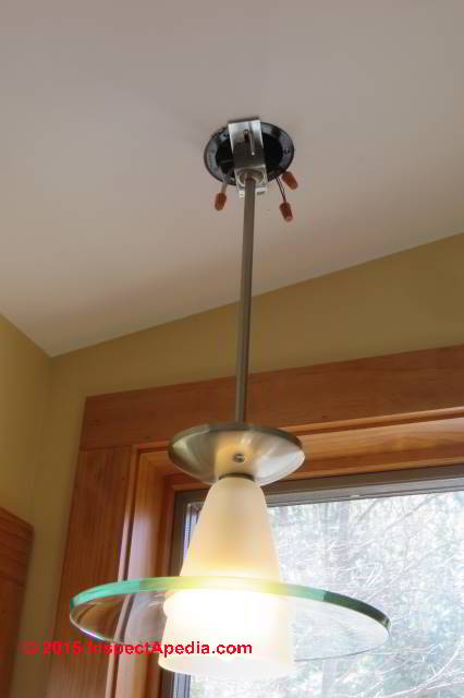
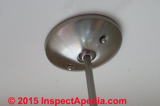
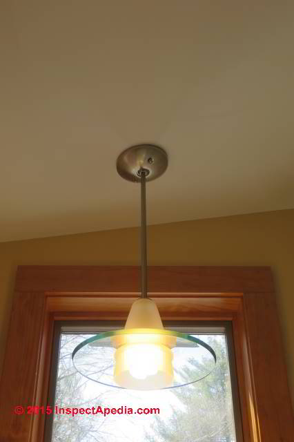
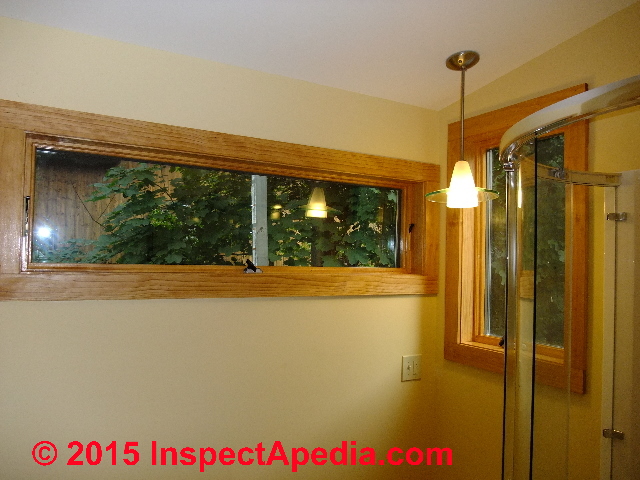 About a year after the light fixture shown at left was installed we observed that it was falling away from the ceiling!
Watch out: any loose electrical fixture is likely to involve a shock or fire hazard. It needs to be repaired.
The cause of the trouble, wrong type and broken mounts in a plastic electrical box used in the ceiling are discussed at the preceding article:
PLASTIC ELECTRICAL BOX REPAIR.
Here we explain how to repair the falling ceiling light while avoiding having to disturb or cut open the ceiling by using a well-secured old-work electrical box designed to be inserted through a just-fit hole in a ceiling or wall.
[Click to enlarge any image]
The best repair for this hang-dog light fixture would be the insertion of an electrical box supported by a telescoping support bar that in turn is secured to the ceiling joists.
In this home, with spaced I-joist ceiling framing that was packed with sprayed-in insulation we wanted to try a simpler repair that would avoid having to hack out the insulation or rip down the ceiling to effect a reliable repair.
We reasoned that the particular light fixture is light-weight and that the failure of the original electrical box was not due to the weight of the light fixture, nor was it due to breakage of the ceiling drywall (though that could certainly happen if there were roof leaks from above).
We knew that the original installer had broken all of the swing clamps on the original old-work electrical box.
Shopping for a heavier old-work swing-clamp electrical box was an easy and tempting solution.
15 Easy Steps to Replace a Damaged Ceiling Light Fixture Box
Below are the detailed steps in the repair procedure for re-connecting and re-hanging the ceiling light fixture. In the short time of an ensuing five years the repair described below has performed without any sign of movement nor other trouble.
- Turn off electrical power and confirm that it is off where the electrical work is to be performed.
See ELECTRICAL TOOLS BASICfor using a neon tester, DMM, or VOM safely. - Remove the light fixture and set it aside.
- Remove the broken electrical box and inspect it to understand the cause of damage and thus the need for repairs. Below I illustrate two of the three broken swing clamps.
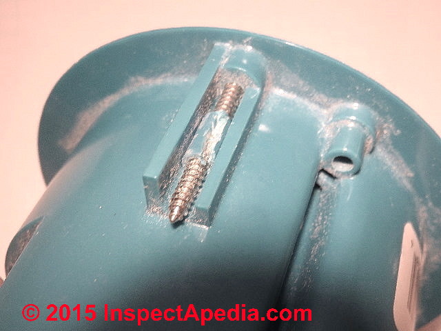
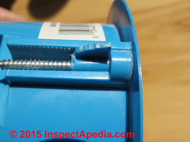
Broken old work electrical box swing clamps: Visual inspection of the broken swing clamps on the electrical box as it was exiting the ceiling showed one swing clamp broken off completely (below) and the other two cracked with broken-off parts. In short the swing clamps intended to hold the box in place had been destroyed during installation.
At below left I've loosened the screw to examine it but when I first looked at this swing clamp the clamp body had been turned down tight against the plastic box stop just as were the other two - see below right.
The swing clamp screws had been so tightened that they were askew in their mounts and the swing clamp screw passages were cracked.
I had also observed that the swing clamp screws were so tight that I had difficulty loosening them: in my view there was ample evidence that they had been over-tightened.
In PLASTIC ELECTRICAL BOX REPAIR - we claim that the over-tightening occurred during original installation of the oldwork box when the installer used a powerful high-torque electric drill to turn down the box mounting clamps. However in that article we also describe other field-observed old work box failiures from other causes.
and
- Inspect the electrical wires for damage: removing and replacing electrical boxes risks cutting or nicking the electrical wire insulation - possibly creating a short circuit or fire hazard. Be sure that the wires to be re-used are un-damaged.
- Inspect the ceiling (or wall) cavity for damage, leaks or other things you'd wish you'd found before trying to shove the new electrical box into place. In this case it was apparent that the original installer had made his job easy by pulling out more ceiling insulation than was necessary.
This gave plenty of room for wire manipulation but it also created a point of heat loss and a hot spot in the roof. We address the insulation voids around the new electrical box in a later step.
Watch out: At this step you need to decide if a structural support for the electrical box is needed or not. Never install a ceiling fan nor a heavy light fixture in a ceiling without proper support: the result will be unsafe and may fall on someone's head.
- Insert the electrical wires into the box: Push the electrical wires into the replacement electrical box through the appropriate wire clamps or openings.
- Insert the electrical box through the opening into the ceiling (or wall).
Tip: Keep your hands clean and avoid making filthy smudges or wire gouges on the ceiling; if you work carefully and avoid unnecessary enlargement of the ceiling opening the ceiling light installation can be completed without having to re-paint the ceiling or repair drywall.
Watch out: avoid kinking or damaging the electrical wires that must be pushed back into the ceiling or wall cavity as you insert the electrical box through its opening. I bend any extra wire length into a round curve that will coil in the open space without kinking.
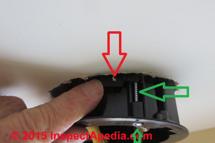
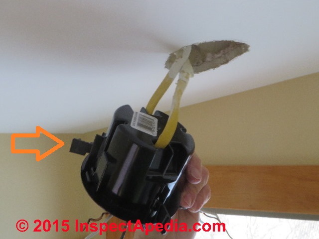
I've left one of the securing ears of the old work electrical box "out" for the photo at above left so that you can see it (below left, orange arrow).
But during installation the rotating ears or clips are pressed flat against the box sides as it is pushed through its mounting hole into the ceiling or wall cavity (below right, red arrow).
During installation of the old work box, its mounting screws (green arrows at above right) are turned causing the plastic ears (red arrow) to rotate open and then pull tight against the drywall or plaster ceiling or wall surfaces, pulling the old work electrical box flange against the exposed side of the ceiling or wall and holding it in place.
- Tighten the oldwork electrical box swing clamp screws.
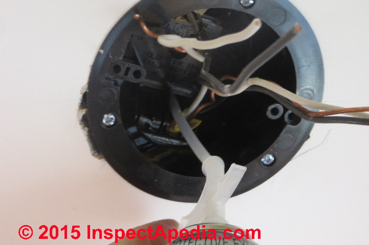
Watch out: if you insist on using a power-screwdriver or a drill-operated screw driver take great care to avoid over-tightening the swing clamp screws lest you crack the clamps, break them, or pull the clamp through a soft drywall surface. - Insulate the building cavity around the electrical box: we used spray foam to fill the voids left around the old work electrical box after it was secure in the ceiling.
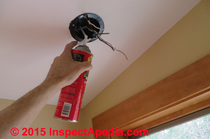
I'm using a closed cell foam insulation that has the added benefit of essentially gluing the electrical box into the ceiling cavity by contact between the box exterior surfaces and the exposed upper surface of the drywall or of any framing reached by the insulating foam.
At below left you will see that I've inserted my foam sprayer nozzle up through an un-used wire entry clamp in the electrical box so that I'm spraying it into the building cavity, not into the box.
Watch out: you or your electrical inspector might prefer that you use fire-rated fire-block foam insulation in this application.
See FIRE-BLOCK Fire Retardant Foam Spray Building Insulation
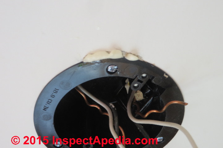
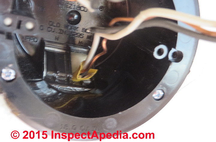
I stopped squirting foam into the ceiling cavity when I saw it beginning to ooze out of an opening at the opposite side of the electrical box (below left), figuring that I'd probably filled the cavity.
Then I waited to see how much foam was going to ooze into the interior of the electrical box itself.
At below right, peering around one of the wires penetrating the electrical box things looked just perfect: you want to foam-fill the building cavity but not the electrical box.
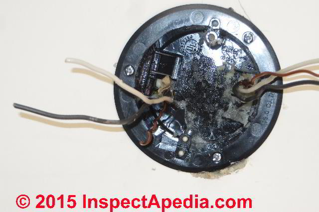
But wait, wait! Wait until the foam has fully cured and hardened. If you try fooling with the foam spray insulation before it has cured you'll find yourself in a horrible sticky gooey mess.
Don't do that. Here is what my "just perfect" foam insulation job looked like when the foam had fully hardened:
Watch out: it would have been safer to use an orange fire-block foam rather than conventional foam insulation in this project.
- Remove excess foam that leaks into the electrical box. Despite working with care, spray foam will expand more than you expect and some is bound to ooze into the electrical box or out of any openings around the box. In fact if you do not see any ooze-out you probably didn't fill the building cavity with insulation.
Wait for the foam to fully cure and harden, then working carefully to avoid nicking any wires, remove all of the excess foam that has oozed into your electrical box.
Watch out: regardless of the type of foam insulation you squirt into the building cavity you do not want to pack the interior of the electrical box itself with foam. Besides the fire and heat issues, the foam will get in the way of wiring, wiring devices, or the pushing of device or fixture wires into the electrical box when the fixture is to be installed.
I used a stainless steel diner knife that has a rounded tip and no sharp edges to carefully loosen and remove the cured foam insulation. The object is to remove the foam (read "fire kindling") without damaging the electrical wires.
The result, above right, is a box empty of foam that might contribute to overheating or to a fire and as well, the electrical wires as well as the box itself are quite securely bonded in place in the ceiling.
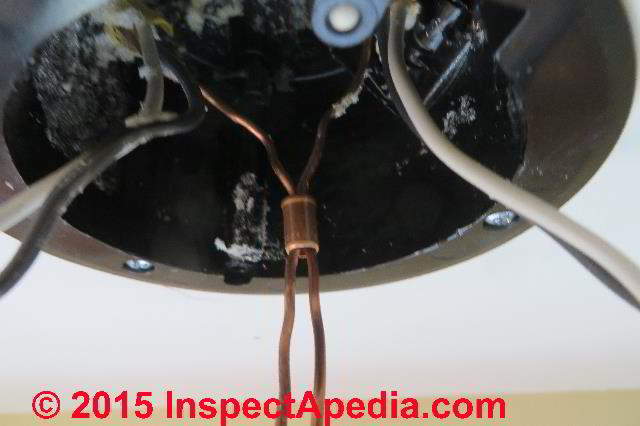
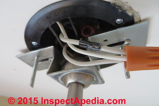
- Prepare the electrical box wires for connection to the light fixture: this includes bonding the circuit grounding conductor wires from the switch circuit and power circuit together. These wires will also be joined with a smaller copper ground wire connected to the light fixture.
Above we slip the copper crimping sleeve over the circuit ground wires;
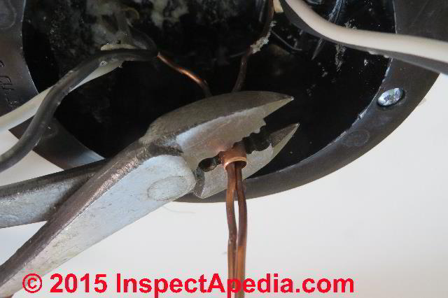
and below we crimp the connector.
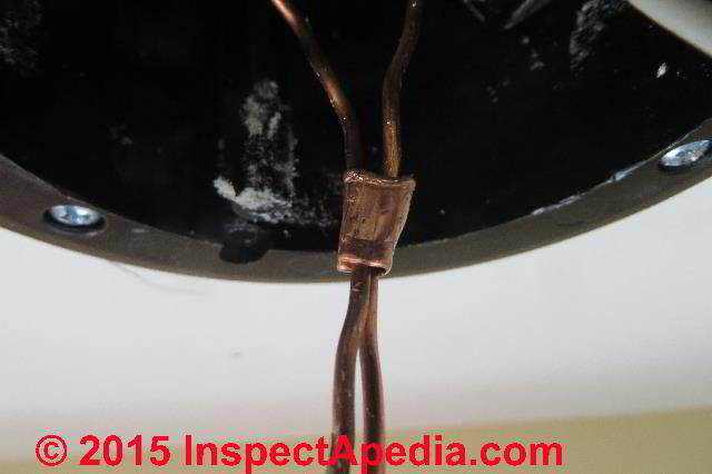
Below you can see the secured crimp connecting the circuit and switch grounding conductors. When the photo was taken that crimp was incomplete. The crimping tool used requires two passes to secure the metal crimping connector.
Watch out: don't try using lineman's pliers or wire cutting pliers to secure a metal wire crimp connector. You'll cut or nick the connector, it won't be properly squeezed, and the connection may be unsafe.
This plastic electrical box did not contain a grounding lug and as it's a plastic box there is no ground wire connected to the box itself.
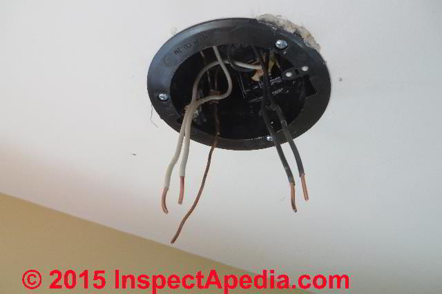
At above right I've arranged the white neutral wires and black hot wires and ground wire where it will be easy to connect them to the matching light fixture wires using twist-on connectors.
- Prepare the light fixture support bracket & wiring for installation. This includes attaching the ceiling light support bracket to the light fixture itself.
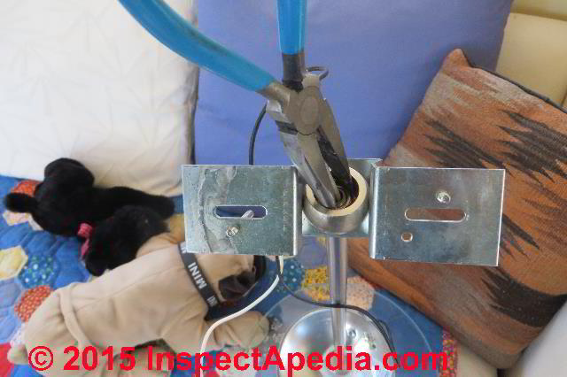
At below left I'm using a pair of flat nose pliers to tighten the nut that attaches the suspended light fixture vertical riser tube to the rounded pendulum that permits the light to hang straight down even when installed on a sloped ceiling.
A conventional socket and socket wrench won't work because it can't fit over the wires passing up through the riser tube.
You'll notice I'm avoiding damage to the glass globe and shade by performing this work on a nearby quilt-covered couch and with the assistance of Mini and Fala, a pair of stuffed animals.
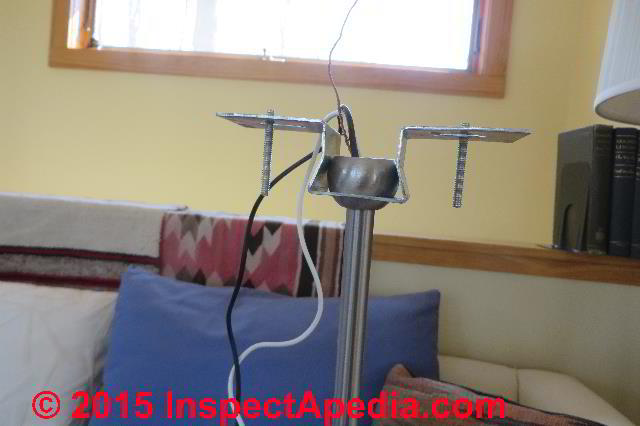
Below, the light fixture support bracket, wires, and screws are in place and ready for the fixture to be lifted to the mounting location.
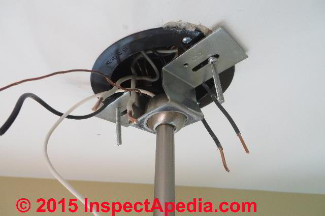
- Connect the light fixture to the supporting electrical box: lift the light fixture into place, connect the light fixture support bracket screws to the electrical box.
Watch out: this is when you'll drop it! Sometimes I connect or wrap the multi-strand copper ground wire belonging to the light fixture to one of the ceiling box screws, preferably a ground screw or lug if one is present: just extra insurance against smashing the whole assembly on the sink or floor below.
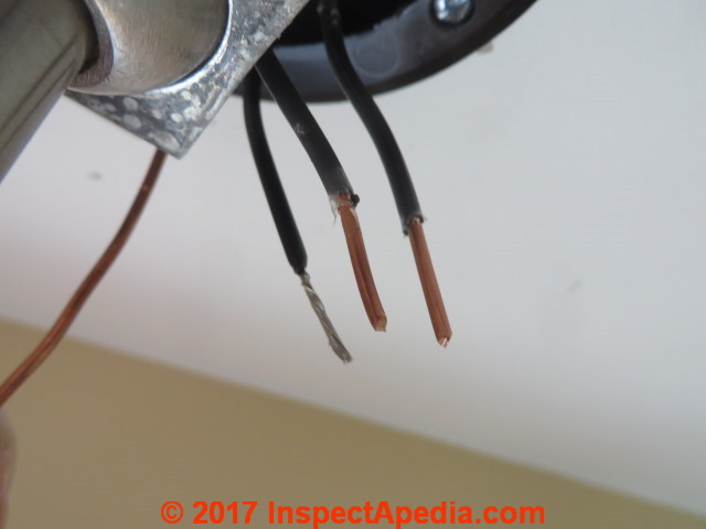
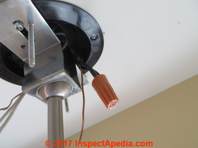
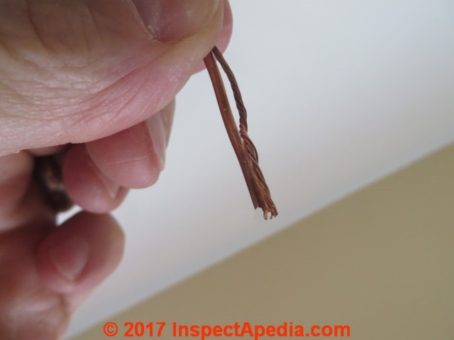
- Connect the light fixture electrical wires to the appropriate circuit wires in the electrical box. Just below at left you can see the smaller multi-strand light fixture black wire ready to be joined with the lighting circuit black wires, and at below right a twist-on connector has completed the connection.
Above left the circuit black or "hot" wires are ready for connection.
Above, wire nut in place.
Typical lighting switched circuit wiring connections:
The circuit "hot" lead (black) is carried to a switch and the wire returning from the switch is connected to the light fixture's "hot" or black wire.
If we're using a simple 2-wire black and white cable to and from the switch then we add a bit of black tape on the returning "hot" white wire to make clear that this is a switched hot wire not a neutral wire
. In that circuit the incoming hot black is connected to the black wire going to the light switch, and the returning light switch white wire is connected to the light fixture's own "hot" or black wire.
We wrap black tape on the returning switch white wire to indicate to a future worker that this is not a neutral wire.
The circuit neutrals and light fixture neutral wires (usually white) are connected together.
The circuit grounding conductors, bonded together in the electrical box, are also connected to the light fixture ground wire. Additional connections may be specified between the light fixture's ground wire and metal fixture support clamps, fixture body, or other metal components that should be grounded for safety.
Above the smaller multi-strand ground wire for the light fixture is ready to be joined to the circuit grounding conductor whose bonding and connections we showed earlier.
We used a twist on connector for this wire pair as well, making future light fixture disassembly and removal easier than if we'd crimp-clamped these wires together.
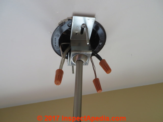
Below: the light fixture wiring connections are complete and we're ready to carefully push the wires back into the electrical box and install the cover. This is when you'll appreciate having enough space in the electrical box.
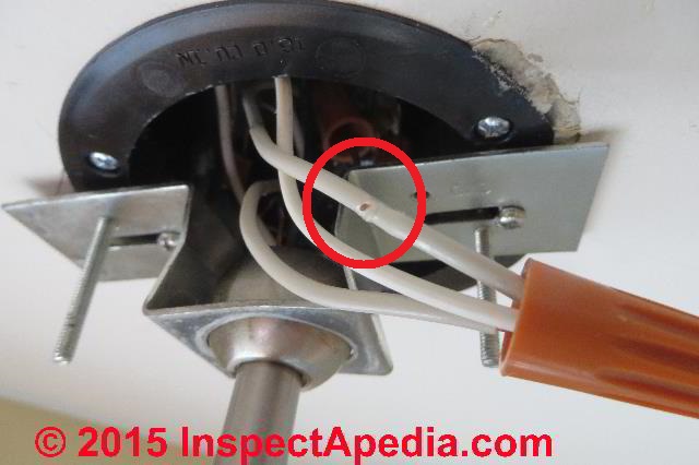
Watch out: it's easy to nick the electrical wire insulation on the sharp edges of the lighting fixture support bracket. If you nick a wire, don't be an ostrich with your head in the sand of fantasy that "it doesn't matter".
Pull the wire out and if it's long enough, cut away the damaged length and make a new connection.
We've seen endless online debate about whether or not it's permissible or NEC code compliant to tape-repair a nicked electrical wire. I'm not going to tell you what you should do, but you can see what some people do do -just below.
- Test the electrical circuit, wiring, & light fixture for safe, proper operation. That's fancy talk for turn it on and see if it works.
You can see that the stainless steel finish cover for the electrical box (blue arrow) is down atop the light fixture globe while it is waiting for us to push wires into the electrical box. Test first, push wires second. The fewer times you have to bend and unbend copper electrical wires the better.
Too much bending anneals and hardens the copper wire making future work more difficult and broken wires more likely.
- Push the electrical wires into the electrical box. Take care to avoid sharp bends, kinks, nicks in the wire insulation or other amateur tricks such as loosening the twist on connectors and watching one of them fall into the sink trap.
- Install the light fixture electrical box cover.
There may be more trouble to this final step than you think: if the cover mounting screws are too long you cannot tighten the cover against the ceiling. If they are too short ... well that's obvious.
Adjusting the light fixture cover mounting screw length
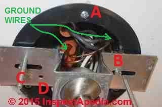
In the photo above the red letters indicate the various screws and fittings for a ceiling light fixture installation:
- A - The screws through the electrical box flange operate the swing clips securing the box to the wall in this case ceiling
- B - The screw heads closest to the (B) indicate the screws that secure the light fixture support bracket to the electrical box that itself must be soundly fastened to the building structure lest your light fall on your head.
- C - The longer threaded screw rods are intended to hold the light fixture cover in place. But if these are too long, the cap nuts won't turn up fast against the cover plate.
- D - is a tapping to accept a ground wire connecting screw where required. Often we'll wrap the light fixture's own multi-strand ground wire around this screw before continuing to connect it to the electrical circuit grounding conductor: check the installation instructions for your light fixture.
Why not just screw the too-long cover mounting screws up into the electrical box? Well sometimes you can, but on this box the cover mounting screws, installed at the width required to match the cover plate, run into the electrical box flange - they won't disappear up into the electrical box.
Also I'm worried about nicking and damaging a wire in the electrical box. We've already been there at least once, right?
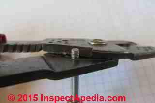
At below left I'm using an electricians wire stripping and cutting tool to snip off the too-long portion of our cover mounting screws without destroying the screw threads. Screw the too-long screw into the matching threaded hole on your screw or bolt cutting tool and snip.
When you un-screw the shortened screw its threads will be intact and will save a good ten minutes of fiddling around trying to get the screw started in its mounting hole.
Just below you can see the cap nuts securely in place and the light fixture cover plate nicely against the ceiling surface.
Below is the ceiling light fixture after the installation was complete.
Watch out: unless your ceiling-mounted electrical box is adequately supported, the procedures described here may not meet approval of your local electrical inspector when a fan or weighty ceiling light fixture is to be installed.
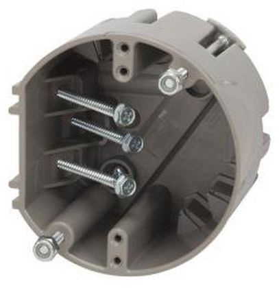
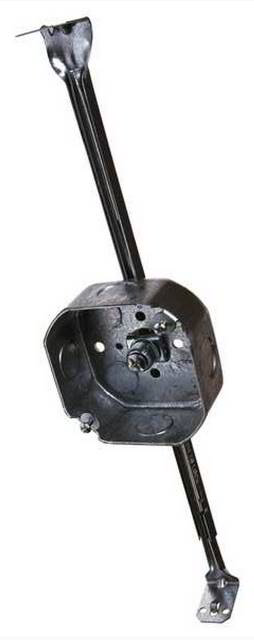
When mounting a heavy ceiling light and certainly if mounting a ceiling fan through an existing ceiling, the old-work electrical box can be secured directly to wood framing (below left, using a Madison Electric Products Smart Box as example), or if the exact light support location does not permit that direct connection one could use an old-work fan bar hanger that includes a deep 4-inch octagon box (below left - Racon fan box support).
OLD WORK ELECTRICAL BOXES for RETROFIT
...
Continue reading at LIGHT SWITCH WIRING DETAILS or select a topic from the closely-related articles below, or see the complete ARTICLE INDEX.
Or see these
Recommended Articles
- CEILING LIGHT FIXTURE INSTALLATION
- ELECTRICAL BOX SCREW REPAIR
- ELECTRICAL JUNCTION BOX TYPES
- ELECTRICAL OUTLET, HOW TO ADD & WIRE
- LIGHT SWITCH WIRING DETAILS
- OLD WORK ELECTRICAL BOXES for RETROFIT
- PLASTIC ELECTRICAL BOX REPAIR
Suggested citation for this web page
CEILING LIGHT FIXTURE INSTALLATION at InspectApedia.com - online encyclopedia of building & environmental inspection, testing, diagnosis, repair, & problem prevention advice.
Or see this
INDEX to RELATED ARTICLES: ARTICLE INDEX to ELECTRICAL INSPECTION & TESTING
Or use the SEARCH BOX found below to Ask a Question or Search InspectApedia
Ask a Question or Search InspectApedia
Try the search box just below, or if you prefer, post a question or comment in the Comments box below and we will respond promptly.
Search the InspectApedia website
Note: appearance of your Comment below may be delayed: if your comment contains an image, photograph, web link, or text that looks to the software as if it might be a web link, your posting will appear after it has been approved by a moderator. Apologies for the delay.
Only one image can be added per comment but you can post as many comments, and therefore images, as you like.
You will not receive a notification when a response to your question has been posted.
Please bookmark this page to make it easy for you to check back for our response.
IF above you see "Comment Form is loading comments..." then COMMENT BOX - countable.ca / bawkbox.com IS NOT WORKING.
In any case you are welcome to send an email directly to us at InspectApedia.com at editor@inspectApedia.com
We'll reply to you directly. Please help us help you by noting, in your email, the URL of the InspectApedia page where you wanted to comment.
Citations & References
In addition to any citations in the article above, a full list is available on request.
- [1] Larry E. Mears, "Support clips for supporting electrical fixtures in a junction box", Patent number: 4679882 Filing date: Sep 17, 1985 Issue date: Jul 14, 1987, Description: Support clips for supporting the mounting brackets of an electrical fixture in a junction box are disclosed. The clips are formed from a single piece of sheet material and are adapted at one end to be crimped between the junction box and the junction box cover, and at the other end to engage and support the mounting brackets disposed on the ends of the fixture. In the case where the electrical fixture is a duplex receptacle, the clips serve to prevent the pivoting of the receptacle about a single center mounting screw during insertion of a plug into one of the receptacle outlets, and thereby prevent the mounting screw from loosening after repeated usage of the receptacle. retrieved 3/4/2013
- [2] Pimentel, Demetrio (Atlanta, GA), patent application No. 10/058762, filed 01/30/2002, is described as follows:
A cover for an electrical outlet box which includes a plurality of bendable mounting clips constructed unitarily with the cover. In use, the mounting clips are oriented perpendicular to the outlet box cover and extend outwardly through an opening in a wall structure with the outer ends of the mounting clips then being bent outwardly into overlying engagement with the exterior of the wall surface in opposed relation to the outlet box cover thereby mounting the outlet box, and cover on the wall structure in alignment with the opening in the wall structure. The outlet box cover is mounted on the outlet box in a conventional manner and the mounting clips on the outlet box cover extend from the periphery of an opening in the cover for mounting electrical sockets, switches or the like in the outlet box in a conventional manner. Retrieved 3/4/2012 - Our recommended books about building & mechanical systems design, inspection, problem diagnosis, and repair, and about indoor environment and IAQ testing, diagnosis, and cleanup are at the InspectAPedia Bookstore. Also see our Book Reviews - InspectAPedia.
- In addition to citations & references found in this article, see the research citations given at the end of the related articles found at our suggested
CONTINUE READING or RECOMMENDED ARTICLES.
- Carson, Dunlop & Associates Ltd., 120 Carlton Street Suite 407, Toronto ON M5A 4K2. Tel: (416) 964-9415 1-800-268-7070 Email: info@carsondunlop.com. Alan Carson is a past president of ASHI, the American Society of Home Inspectors.
Thanks to Alan Carson and Bob Dunlop, for permission for InspectAPedia to use text excerpts from The HOME REFERENCE BOOK - the Encyclopedia of Homes and to use illustrations from The ILLUSTRATED HOME .
Carson Dunlop Associates provides extensive home inspection education and report writing material. In gratitude we provide links to tsome Carson Dunlop Associates products and services.


