
InspectAPedia® FREE Encyclopedia of Building & Environmental Construction, Diagnosis, Maintenance & Repair |
Question? Just ask us! InspectAPedia
|
 Combustion Air Requirements
How to Recognize, Test, & Diagnose
Heating Appliance Combustion Air Problems
- POST a QUESTION or COMMENT about combustion air requirements and safety hazards for oil and gas fired heating appliances
Combustion air defects & hazards.
This article explains how to recognize and fix combustion air defects on heating appliances such as boilers, furnaces, and water heaters.
This article series answers most questions about central hot water heating system troubleshooting, inspection, diagnosis, and repairs.
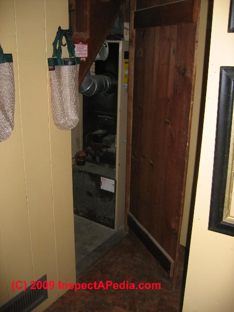
Our photo at page top shows an oil fired furnace installed in a closet with an airtight door; there was no outside combustion air supply. The heating system could not work properly nor safely in this home.
InspectAPedia tolerates no conflicts of interest. We have no relationship with advertisers, products, or services discussed at this website.
- Daniel Friedman, Publisher/Editor/Author - See WHO ARE WE?
Heating Equipment Combustion Air Requirements & Hazards
 How to recognize, diagnose & fix inadequate combustion air, sooting, or burn marks at oil-fired or gas-fired heating systems.
Watch out: inadequate combustion air not only causes improper and wasteful operation of heating equipment it can also produce fatal carbon monoxide gas hazards indoors.
Lack of adequate combustion air causes improper heater operation, increased maintenance cost, and risks dangerous production of carbon monoxide gas. This article series explains how to recognize & diagnose problems with residential heating boilers, including loss of heat, heating boiler noises, leaks, odors, or smoke, and high heating costs.
The quantity of combustion air needed depends on the fuel type, the input BTUh rating of the heating equipment, and additional air needed to assure effective exhaust draft to carry combustion products safely out of the building.
Topics discussed here include:
How to diagnose signs of inadequate combustion air for an oil or gas burner.
- Dangers of carbon monoxide poisoning if there is soot production at gas fired heating appliances
- Inadequate combustion air can cause dangerous carbon monoxide gas in buildings.
- Combustion air safety check procedure for gas fired heating equipment.
- How to test for safe combustion air for gas fired heating appliances, water heaters, etc.
- Combustion Air Defects & Safety Hazards at Mobile Home Heating System.
- How is outside combustion air provided to a woodstove?
Article Index
- SIGNS of INADEQUATE COMBUSTION AIR - and why that's unsafe
- COMBUSTION AIR INLET SIZE RULE of THUMB - how many square inches of air intake vent do you need?
- COMBUSTION AIR ADEQUACY vs ROOM SIZE - square feet or cubic feet
- COMBUSTION AIR SUPPLY DUCT SIZE vs HEATER BTUh - table of combustion air duct sizes
- COMBUSTION AIR CODES & MANUALS - building codes set minimum combustion air standards
Watch out: inadequate combustion air supply to a gas burner (and less often to an oil burner) is very dangerous and can produce potentially fatal carbon monoxide.
If you suspect unsafe heating system operation or a carbon monoxide problem be sure everyone leaves the building immediately and then call your local fire department for assistance.
Clues Indicating Possible Lack of Combustion Air & Related Safety Hazards
-
Lack of adequate combustion air
can result in improper system operation, sooting, increased heating cost, damage to oil burner components (back pressure heat can destroy an ignition transformer), higher and more frequent heating service costs, loss of heat, noises, smoke, and potentially, the production of carbon monoxide or other flue or combustion gases which escape into the building - potentially dangerousThese conditions can not only release flue gases into the occupied space, but they are likely to cause the production of potentially fatal carbon monoxide.
We've seen heating equipment that seemed to work just fine during its adjustment because the service technician was working with the door to the furnace or boiler room open.
But when she left the system and closed the furnace room door, suddenly there was insufficient combustion air.Also see Unsafe Air Conditioning or Heating Duct Openings which describes the risks of reduced combustion air on hot air heating systems when certain return air duct defects are present,
and also see CARBON MONOXIDE - CO
and CHIMNEY INSPECTION DIAGNOSIS REPAIR
Watch out: Gas burner sooting or odors: SAFETY WARNING: Small amounts of soot or flame marks right at the gas burner also indicate an operating problem but may not be producing carbon monoxide.
But soot produced at a gas fired appliance such as chunks of soot found around a gas flue vent or draft hood is a RED DANGER FLAG as dangerous carbon monoxide may be produced and a chimney may be blocked.
Turn off the equipment and contact your heating service company or utility company immediately.
See CARBON MONOXIDE WARNINGS: HOME HEATERS
and FLUE GAS SPILL SWITCH TRIPPING & RESET
Watch Out: The sketch shown below, courtesy of Carson Dunlop Associates, explains how dangerous furnace back-drafting can occur when there is insufficient combustion air.

- Improper oil burner system operation such as noises, rumbling, etc. discussed
at OIL BURNER NOISE SMOKE ODORS
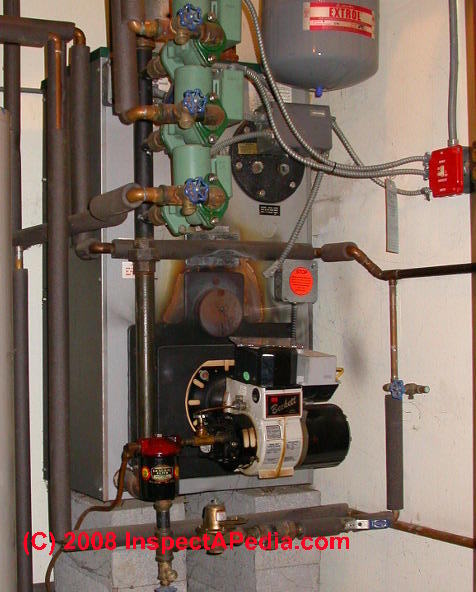
- Oil burner sooting or dirty operation (photo above)
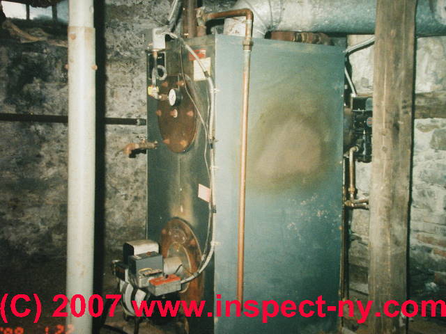
- Burn marks on the boiler (photo above), furnace, or water heater, (these conditions may be caused by a blocked exhaust flue and inadequate venting).
Watch out: burn marks on a heating boiler or furnace (shown in our page top photo) can also be due to collapse or damage to the combustion chamber liner - a serious fire hazard needing immediate attention.
Notice that in our photo below the brown burn marks around the oil boiler combustion chamber inspection port (that rusty round door above the oil burner) have been cleaned-off.
The presence of these burn marks does not necessarily mean that the oil burner backpressure problem remains - in this case the system has been cleaned and adjusted, but no one has re-painted the front of the boiler. But if you see fresh peeling paint or soot in such an area further investigation is needed.
That's why we recommend that after repairing a back-pressure problem at heating equipment the service technician should clean the boiler or furnace exterior - to remove confusing debris and to make it easier to see if the problem recurs.
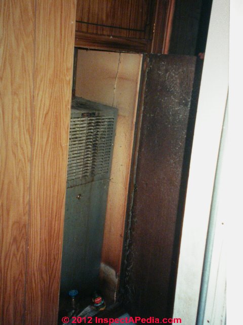
- Heating equipment located in a small utility room with no provision for combustion air intake. (photo below in a mobile home - no outside combustion air either)
When the service technician adjusts the system she probably worked with the utility room door open, but when the service tech left the job he may have closed the door - completely changing the availability of combustion air for the equipment.
We need about one square inch of un-louvered (unobstructed) combustion air intake per 1000 btuh of the oil fired heating boiler, furnace, or water heater.
- Increased heating system operating cost, spending more on heating oil than necessary
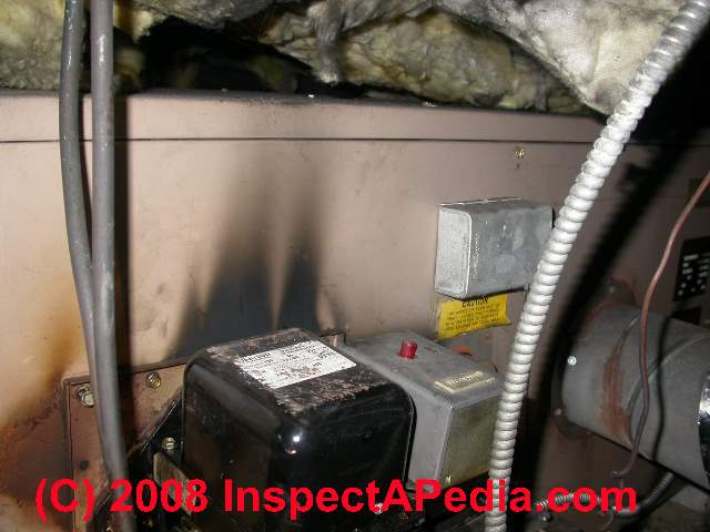
- Damage to oil burner components (backpressure heat can destroy an ignition transformer),
- Higher and more frequent heating service calls & costs
- Loss of heat, the heating system goes off on safety reset
- Noises in the heating equipment or chimney when the boiler, furnace, or water heater starts, is operating, or is shutting down
- Smoke or soot indoors,coming out of the heating equipment or its draft regulator
- Carbon monoxide or CO alarms: Potentially, the production of carbon monoxide or other flue or combustion gases which escape into the building - potentially dangerous or even fatal. It is harder to produce with oil heat than with gas heat, but not impossible.
Also see UNSAFE HVAC DUCT OPENINGS which describes the risks of
reduced combustion air on hot air heating systems when certain return air duct defects are present,
and
also see CARBON MONOXIDE - CO
and CHIMNEY INSPECTION DIAGNOSIS REPAIR
Heating Equipment Combustion Air Rules of Thumb
Square Inches of Combustion Air Intake: 1 sq. in. per 1000 BTUH
For heating equipment installed in confined spaces, an old-timer's rule of thumb is to add up the total INPUT BTUH numbers from all of the data tags on all of the heating equipment installed. You want to see at least one sq. in. of open fresh air intake per 1000 btuh.
Total Sq .In. of Combustion Air Intake Opening = Total Input BTUH / 1000
Watch out: this combustion air rule of thumb needs to be adjusted to account for the air flow restriction caused by louvers and screening over the combustion air intake opening. As a rule of thumb we
Reduce the effective total square inches of combustion air intake opening by at least 1/3 for louvers & screens
Reduce the effective total square inches of combustion air opening further if the screen is or can easily become clogged by lint, leaves, trash & debris
Watch out: The combustion air estimate provided by outside combustion air openings or openings into other, presumably larger building areas (see below) also needs to account for the effects of building exhaust fans, tight buildings, and similar interferences.
See BACKDRAFTING HEATING EQUIPMENT.
Watch out: this rule of thumb falls apart if the fresh air is not being vented directly into the heating equipment area through an outside wall.
That is, if air has to move through vent pipes or ductwork into the area where it is needed, the equivalent square inches of fresh air intake venting may need to be increased depending on the length, number of bends, angles of bends, and diameter of the fresh air or combustion air intake venting system.
Standard engineering approaches to calculating air flow through round or rectangular ductwork can solve the question of impact on combustion air of routing it through ducts.
Cubic Feet of Room Space as a Measure of Adequacy of Combustion Air: Total Input BTUH / 1000 x 50
For heating equipment installed in larger spaces, a common rule of thumb for computing the required total cubic feet of free space to assure adequate combustion air is to provide 50 cubic feet of free space per 1000 Input BTUH for the total of all of the heating appliances installed in the area.
The assumption behind this old rule is that buildings leak air and that larger rooms or spaces have more air intake leaks than smaller ones.
Total Cubic Feet of Free Area = Total Input BTUH / 1000 x 50
Watch out: this formula may not adequately consider the reduction in volume of the room or open space attributed to contents, storage, etc. and it certainly does not adjust for modern tight building construction.
COMBUSTION AIR for TIGHT BUILDINGS explains how to provide outside combustion air for tight buildings.
Some writers simplify the formula to express this rule of thumb as
Total Cubic Feet of Free Area = Total Input BTUH x .05
Example: if we have a 180,000 Input BTUH boiler and a 40,000 input BTUH water heater installed in an enclosed utility room, how many cubic feet of space in that room would make us think we had adequate combustion air?
(180,000 + 40,000) / 1000 x 50
220,000 BTUH / 1000 = 220
220 x 50 = 11,000 cubic feet.
If our room is smaller than 11,000 cubic feet we probably don't have adequate combustion air (unless an outside combustion air source is also provided).
Calculate the total cubic feet of space in a room by multiplying the room width x room length x room height
Example: if the heating equipment is installed in an open basement that is 40 ft. x 20 ft. x 8 ft. high, we have
Cubic Feet = 40 x 20 x 80
Cubic Feet = 6400 - this basement will probably not provide adequate combustion air for the example input BTUH total given above.
Special thanks to reader Joe who corrected a math error in the above, 14 Jan 2016
Table of Combustion Air Supply Duct Sizes vs BTUh
Watch out: square duct area is not equal to round duct area in air flow capacity. That's because air flowing through a square or rectangular duct (or chimney) does not flow uniformly - the area of the corners of the rectangle moves less air.
For you who left your calculator at home and left Pi in the refrigerator, here is the square inches of cross section opening size for common round duct diameters:
Table of Combustion Air Supply Duct Sizes vs. Input BTUh for Natural Draft Heating Appliances |
||
|---|---|---|
| Round Duct Diameter in Inches |
Duct Cross Section Square Inches (Round Opening Size) |
Approximate Total Input BTUH Supported at This Combustion Air Duct-Vent Opening Diameter2 |
| 12 | ||
Notes to the Table Above
1. This data is for round ducts and smooth metal duct sides; lengths of flex duct with ribbed or corrugated sides restricts air flow and will not provide as much equivalent air flow.
Reference: "Evaluating Duct Work, How to Evaluate Furnace Duct Work &
Cure Short Cycling or Inadequate Ductwork Problems" Vermont Department for Children and Families, Office of Economic Opportunity, - dcf.vermont.gov/sites/dcf/files/pdf/oeo/WAPManual/AppendixI.pdf retrieved 12/5/2013
2. Really? We need further research on these figures. they significantly exceed the 1000 BTUH per square inch of area. Citation: David Clark, Home Inspection Newsletter, retrieved 12/5/2013 http://turnkeyhomeinspectors.com/turnkeyhomeinspectors_004.htm
3. These numbers are for round opening sizes used to provide combustion air to heating equipment.
See SUPPLY DUCTS & REGISTERS for details about HVAC heating or cooling supply & return air duct sizing, air flow, and for matching HVAC air duct sizes to equipment BTUH rate or heating capacity.
How to Convert Round Opening Diameters (say an air duct cross section) to Opening Size Equivalent
If we are using smooth-walled round ducts to bring combustion air into the space where it is needed, and before considering the restrictions on air flow caused by duct bends and length (friction losses) we start by simply calculating the cross-sectional area of the duct:
Pi r2 = the area of a circle or the cross-sectional area of a round combustion air supply duct
Pi (also written as Π) = 3.1416 - a constant
r = the radius = half of the diameter of the circle
We can use any unit (cm, inches, feet) as long as we stick to the same unit through.
Example: a 6-inch diameter round air duct has a cross section (or area) of
Area = 3.1416 x (6 / 2)2 inches
Area = 3.1416 x (3)2 inches
Area = 3.1416 x (3 x 3)
Area = 28 sq. in. of space - which, if unrestricted by duct length, bends, or screens, and if we use our first rule of thumb (one inch per 1000 BTUH) would support about 28,000 Input BTUH
Combine Combustion Air Sources to Check the Combustion Air Requirements
When room volume in cubic feet is inadequate to provide safe combustion air we can add combustion air by providing an outside air source.
Combustion Air Equipment Manuals & Codes
- Beckett, OUTSIDE COMBUSTION AIR INTAKE INSTALLATION INSTRUCTIONS [PDF] Beckett oil burner models AF/AFD/AFG, retrieved 2018/03/14, original source: http://www.h-mac.com/product-catalogs/sterling/Combustion-Air-Adapter-Kit.pdf
- Beckett COMBUSTION AIR REQUIREMENTS for OIL BURNERS [PDF] Beckett Corporation,
- Field Controls, COMBUSTION AIR SYSTEM CAS-2WM MANUAL [PDF](2009) Weil McLain Outside Air Kit for Oil Burner Models QB180 & QB300, Field Controls, LLC., Tel: 252-522-3031, Website: www.fieldcontrols.com, retrieved 2018/03/14, original source: https://www.torrco.com/ASSETS/DOCUMENTS/CMS/EN/IAH-4-overview.pdf
- Field Controls, COMBUSTION AIR SYSTEM CAS-2B, 2C, 2W MANUAL [PDF] CAS-2B for Beckett-AF/AFG oil burner, CAS-2C for Carlin EZ-1/CRD/FRD oil burners, CAS-2W for Wayne-MSR oil burners, , retrieved 2018/03/14, original source: http://www.republicsupplyco.com/SpecSheets/46273500.pdf
Also see OIL BURNER MANUALS
IRC Mechanical Code Section 71. COMBUSTION, VENTILATION AND DILUTION AIR Section M1701, G2407 (304) IRC 2009
Section M1701 General
M1701.1 Scope.
Solid-fuel-burning appliances shall be provided with combustion air in accordance with the appliance manufacturer’s installation instructions. Oil-fired appliances shall be provided with combustion air in accordance with
NFPA 31. The methods of providing combustion air in this chapter do not apply to fireplaces, fireplace stoves and directvent appliances.
The requirements for combustion and dilution air for gas-fired appliances shall be in accordance with Chapter 24.
M1701.2 Opening location.
In areas prone to flooding as established in Table R301.2(1), combustion air openings shall be located at or above the elevation required in Section R322.2.1 or R322.3.2.
G2407.1 (304.1) General.
Air for combustion, ventilation and dilution of flue gases for appliances installed in buildings shall be provided by application of one of the methods prescribed in Sections G2407.5 through G2407.9.
Where the requirements of Section G2407.5 are not met, outdoor air shall be introduced in accordance with one of the methods prescribed in Sections G2407.6 through G2407.9.
Direct-vent appliances, gas appliances of other than natural draft
design and vented gas appliances other than Category I shall be provided with combustion, ventilation and dilution air in accordance with the appliance manufacturer’s instructions.
Exception: Type 1 clothes dryers that are provided with makeup air in accordance with Section G2439.4.
G2407.5 (304.5) Indoor combustion air.
The required volume of indoor air shall be determined in accordance with Section G2407.5.1 or G2407.5.2, except that where the air infiltration rate is known to be less than 0.40 air changes per hour (ACH), SectionG2407.5.2 shall be used.
The total required volume shall be the sum of the required volume calculated for all appliances located within the space.
Rooms communicating directly with the space in which the appliances are installed through openings not furnished with doors, and through combustion air openings sized and
located in accordance with Section G2407.5.3, are considered to be part of the required volume.
G2407.5.3 (304.5.3) Indoor opening size and location.
Openings used to connect indoor spaces shall be sized and located in accordance with Sections G2407.5.3.1 and G2407.5.3.2 (see Figure G2407.5.3).
G2407.5.3.1 (304.5.3.1) Combining spaces on the same story.
Each opening shall have a minimum free area of 1 square inch per 1,000 Btu/h (2,200 mm2/kW) of the total input rating of all appliances in the space, but not less than 100 square inches (0.06 m2).
One opening shall commence within 12 inches (305mm) of the top and one opening shall commence within 12 inches (305 mm) of the bottom of the enclosure.
The minimum dimension of air openings shall be not less than 3 inches (76 mm).
G2407.5.3.2 (304.5.3.2) Combining spaces in different stories.
The volumes of spaces in different stories shall
be considered as communicating spaces where such spaces are connected by one or more openings in doors or floors having a total minimum free area of 2 square inches per 1,000 Btu/h (4402mm2/kW) of total input rating of all appliances.
G2407.6 (304.6) Outdoor combustion air.
Outdoor combustion air shall be provided through opening(s) to the outdoors in accordance with Section G2407.6.1 or G2407.6.2. The minimum dimension of air openings shall be not less than 3 inches (76 mm).
G2407.6.1 (304.6.1) Two-permanent-openings method.
Two permanent openings, one commencing within 12 inches (305 mm) of the top and one commencing within 12 inches (305 mm) of the bottom of the enclosure, shall be provided. The openings shall communicate directly, or by ducts, with the outdoors or spaces that freely communicate with the outdoors.
Where directly communicating with the outdoors, or where communicating with the outdoors through vertical ducts, each opening shall have a minimum free area of 1 square inch per 4,000 Btu/h (550mm2/kW) of total input rating of all appliances in the enclosure [see Figures G2407.6.1(1) and G2407.6.1(2)].
Where communicating with the outdoors through horizontal ducts, each opening shall have a minimum free area of not less than 1 square inch per 2,000 Btu/h (1,100 mm2/kW) of total input rating of all appliances in the enclosure [see Figure G2407.6.1(3)].
G2407.6.2 (304.6.2) One-permanent-opening method.
One permanent opening, commencing within 12 inches (305 mm) of the top of the enclosure, shall be provided.
The appliance shall have clearances of at least 1 inch (25 mm) from the sides and back and 6 inches (152 mm) from the front of the appliance.
The opening shall directly communicate with the outdoors or through a vertical or horizontal duct to the outdoors, or spaces that freely communicate with the outdoors (see Figure G2407.6.2) and shall have a minimum free area of 1 square inch per 3,000 Btu/h (734 mm2/kW) of the total input rating of all appliances located in the enclosure and not less than the sum of the areas of all vent connectors in the space.
Original source:
- Stevens WA, COMMONLY USED RESIDENTIAL BUILDING CODES, IRC 2009, [PDF] retrieved 2019/05/08 original source: http://www.co.stevens.wa.us/landservices/documents/MECHANICALSECTION.pdf
- Other sections of this mechanical code are given
at CHIMNEY HEIGHT & CLEARANCE COD
...
Reader Comments, Questions & Answers About The Article Above
Below you will find questions and answers previously posted on this page at its page bottom reader comment box.
Reader Q&A - also see RECOMMENDED ARTICLES & FAQs
Shared exhaust flue between natural draft and power-vented heaters may be unsafe
I have a mechanical room that has two large furnaces and one water heater. The two furnaces do not have powered exhaust vents, the water heater does. Question: May these three appliances vent into the same chimney? - 2020-12-14 by Robert Recher -
Reply by (mod) -
Sending a powered and not powered draft heating Appliance into the same chimney sounds dangerous to me. There's at least a risk of backdrafting.
Our heater fumes are giving me headaches
If outside air is flowing in ur heater closet and is not letting the heater furnes work and I'm getting bad headaches - 2018-02-24 by Miguel -
Reply by (mod) -
MIguel
Watch out: The situation you describe sounds unsafe - it could kill you with carbon monoxide poisoning.
Do not go to sleep in such a building. BE SURE you have properly located, installed, and tested carbon dioxide detectors (CO Monitors) in your home,
NOW go outside, call your heating company to inspect and repair the system.
How many cubic feet of exhaust gas is generated per 1000 BTUs of Propane Burned?
Can someone tell me the cubic of gases (including water vapor) generated from burning 1000 btus of propane? - 2017-10-08 by Frank -
On 2017-10-09 - by (mod) - Here's the formula to calculate the complete combustion of propane and the amount of each combustion product
Frank,
The equation for complete combustion of propane is
C3H8 + 5 O2 → 3 CO2 + 4 H2O + heat
We use larger numbers to answer your question to avoid many decimal points in a very small number:
Burning 1 million BTUs of propane will produce 62.7 kg or 138 pounds of CO2.
Burning propane produces 0.98 gallons of water per 100,000 BTUH. That is, a 100,000 BTUH propane heater produces about a gallon of water per hour or about a gallon of water per 100,000 BTUs of heat produced by burning propane.
Propane combustion produces other substances as the US EPA notes:
LPG is considered a "clean" fuel because it does not produce visible emissions. However,
gaseous pollutants such as nitrogen oxides (NOx), carbon monoxide (CO), and organic compounds are
produced as are small amounts of sulfur dioxide (SO2) and particulate matter (PM).
Since at NATURAL GAS & PROPANE COMBUSTION PRODUCTS https://inspectapedia.com/hazmat/Gas_Combustion_Products.php we note that burning a gallon of propane produces 91,000 BTUS of energy (heat) and 1.64 pounds of water, we can figure that burning 1000 BTUs of propane will produce 1.64/91 gallons of water or 0.18 gallons of water. That water is of course in vapor form whose vapor volume will vary depending on temperature and perhaps other factors.
There we also note the other combustion products and volumes from burning propane. We avoid giving an answer in cubic feet (you didn't give me a cubic "what" measurement) because the volume of a gas depends also on its pressure (we can assume atmospheric pressure) and temperature (that we don't know for your heater but a typical gas furnace will be operating around 110-140 degF depending on when and exactly where you make the measurement).
Combustion Air Requirements Specifications for Power Burners
For combustion air requirements for power burner fired heating appliances
see COMBUSTION AIR for POWER BURNERS
Combustion Air Inlet by Automatically Operated Louvers or Dampers
This topic has moved to a new article at COMBUSTION AIR INLET AUTOMATIC LOUVERS
Combustion Air Inlets vs Cold Drafts
This sub-topic has moved to COMBUSTION AIR INLETS vs COLD DRAFTS found
in COMBUSTION AIR INLET AUTOMATIC LOUVERS
Guide to a Simple Combustion Air Safety Check for Gas Fired Heating Appliances
See COMBUSTION AIR SAFETY CHECK
Combustion Air Defects & Safety Hazards at Mobile Home Heating System
We moved this article to COMBUSTION AIR SAFETY in MOBILE HOMES
Combustion Air for Woodstoves - How is It Provided?
Please see the new home for this article topic now found at COMBUSTION AIR for WOODSTOVES
A Guide to Combustion-Air-Related Heating Equipment Malfunctions & Their Implications
This topic moved to COMBUSTION AIR DEFECT EFFECTS
...
Continue reading at COMBUSTION AIR for POWER BURNERS or select a topic from the closely-related articles below, or see the complete ARTICLE INDEX.
Or see COMBUSTION AIR REQUIREMENT FAQs - questions & answers posted originally at this page
Or see these
Recommended Articles
- BACKDRAFTING HEATING EQUIPMENT
- CARBON MONOXIDE - CO
- COMBUSTION AIR REQUIREMENTS
- CLUES INDICATING INADEQUATE COMBUSTION AIR
- COMBUSTION AIR DEFECTS
- COMBUSTION AIR DEFECT EFFECTS
- COMBUSTION AIR RULES of THUMB
- COMBUSTION AIR vs ROOM SIZE
- COMBUSTION AIR DUCT SIZE vs BTUh
- COMBUSTION AIR for POWER BURNERS
- COMBUSTION AIR INLET AUTOMATIC LOUVERS
- COMBUSTION AIR INLETS vs COLD DRAFTS
- COMBUSTION AIR SAFETY CHECK
- COMBUSTION AIR SAFETY in MOBILE HOMES
- COMBUSTION AIR for TIGHT BUILDINGS
- COMBUSTION AIR for WOODSTOVES
- UN-VENTED GAS HEATER SAFETY
- COMBUSTION PRODUCTS & IAQ
- COMPLETE COMBUSTION, STOICHIOMETRIC
- DIAGNOSE & FIX HEATING PROBLEMS-BOILER
- DIAGNOSE & FIX FURNACE PROBLEMS - home
- OIL BURNER INSPECTION & REPAIR - home
Suggested citation for this web page
COMBUSTION AIR REQUIREMENTS at InspectApedia.com - online encyclopedia of building & environmental inspection, testing, diagnosis, repair, & problem prevention advice.
Or see this
INDEX to RELATED ARTICLES: ARTICLE INDEX to HEATING SYSTEMS
Or use the SEARCH BOX found below to Ask a Question or Search InspectApedia
Ask a Question or Search InspectApedia
Try the search box just below, or if you prefer, post a question or comment in the Comments box below and we will respond promptly.
Search the InspectApedia website
Comments & Questions are Welcome Here
If you posted comments here and no longer see what you wrote, please check for your comment in the Reader Q&A found above on this page.
Citations & References
In addition to any citations in the article above, a full list is available on request.
- American Society of Heating, Refrigerating and Air-Conditioning Engineers (ASHRAE) Handbook - Fundamentals, 1993, Chapter 15, page 15.9 Air For Combustion.
- ASME CSD-1- Controls and Safety Devices for Automatically Fired Boilers, 1992 with addendum 1a 1993. section CG-260 Combustion Air.
- BOCA - National Mechanical Code, 1990, article 10, Combustion Air.
- NFPA 31 - Installation of Oil Burning Equipment, 1992, section 1-5 Air for Combustion and Ventilation.
- NFPA 54: National Fuel Gas Code (2015), addresses heating appliance combustion air ventilation specifications. NFPA 54, ANSI Z223.1 provides minimum safety requirements for the design and installation of fuel gas piping systems in homes and other buildings.
- NFPA 85: Boiler and Combustion Systems Hazards Code: NFPA 85 contributes to operating safety and prevents explosions and implosions in boilers with greater than 12.5 MMBTUH, pulverized fuel systems, and heat recovery steam generators.
- NFPA 87: Recommended Practice for Fluid Heaters, This recommended practice provides safety guidance for fluid heaters and related equipment to minimize fire and explosion hazards that can endanger the fluid heater, the building, or personnel
- SBCCI- Standard Mechanical Code, 1991, section 305 Combustion and Ventilation Air.
- Axtman, William H., "Combustion Air Requirements: The Forgotten Element in Boiler Rooms", Grayh Gull Associates, retired executive director of the American Boiler Manufacturers Association, National Board Technical Series, Winter 1995 National Board Bulletin. Retrieved 26 January 2015, original source: http://www.nationalboard.org/index.aspx?pageID=164&ID=191
Excerpt:
Several safety codes such as the National Fire Protection Association's standards, NFPA 54 - National Fuel Gas code, NFPA 31 - Installation of Oil Burning Equipment, and the American Society of Mechanical Engineers (ASME) CSD-l Controls and Safety Devices for Automatically Fired Boilers have sections covering the requirements for combustion air intakes.
In addition, building codes such as the Building Officials and Code Administrators International (BOCA) National Mechanical Code and the Standard Mechanical Code published by the Southern Building Code Congress International (SBCCI) have air requirements for combustion.
Editor's note: Some ASME Boiler and Pressure Vessel Code requirements may have changed because of advances in material technology and/or actual experience. The reader is cautioned to refer to the latest edition and addenda of the ASME Boiler and Pressure Vessel Code for current requirements. - Nussbaumer, Thomas. "Combustion and co-combustion of biomass: fundamentals, technologies, and primary measures for emission reduction." Energy & fuels 17, no. 6 (2003): 1510-1521.
- Utiskul, Yunyong P., Wu, Neil P., Biteau, Hubert, "Combstion Air Requirements for Power Burner Appliances, Final Report", The Fire Protection Research Foundation, The Fire Protection Research Foundation
One Batterymarch Park
Quincy, MA, USA 02169-7471
Email: foundation@nfpa.org
http://www.nfpa.org/foundation, retrieved 25 Jan 2015, original source: http://www.nfpa.org/~/media/files/research/research%20foundation/rfcombustionairrequirements.ashx, Executive Summary:
Gas-fired appliances require combustion air to properly function. Adequate air is necessary for supporting combustion of the appliance burner, dilution of flue gas, and proper ventilation of the space where the appliance is installed. Current standards and model codes outline requirements and methods to supply the combustion air.
One method is to provide outdoor combustion air through openings or air ducts communicating with the outdoors through natural ventilation. Most standards require the outdoor opening(s) be prescriptively sized based on the total energy input rating of the appliance.
However, in the United States, the current standards contain no separate provisions to address the opening size supplying the combustion air for commercial/industrial sized appliances, which typically have a high energy input rating of greater than 300 kBtu/hr and are equipped with a power burner unit.
As a result, the opening(s) can be excessively sized when determined based on the current standards.
This research project establishes minimum outdoor combustion air requirements specific to gasfired appliances utilizing power burners with input ratings no greater than 12.5 MBtu/hr.
A review of the available literature, engineering guidelines, and current standards and model codes related to combustion air requirements was performed. This report provides an understanding of the technical basis for the existing provisions for combustion air and their applicability to power burner appliances.
This report also identifies the range of energy input ratings for gasfired appliances equipped with power burners, and compares the combustion air requirements specified by a range of appliance manufacturers.
A theoretical model for air flow through openings was developed and the modeling results, together with the data gathered through the literature review, were used to provide a baseline to establish the theorized combustion air requirements suitable for power burner appliances. ... - [1] Jeff Wilcox, "Evaluating Duct Work, How to Evaluate Furnace Duct Work & Cure Short Cycling or Inadequate Ductwork Problems" Vermont Department for Children and Families, Office of Economic Opportunity, - dcf.vermont.gov/sites/dcf/files/pdf/oeo/WAPManual/AppendixI.pdf retrieved 12/5/2013. Geoff Wilcox Vermont Office of Economic Opportunity Weatherization Assistance Program Waterbury, VT (802) 769-8376 Geoff.wilcox@state.vt.us Reference Material for the original article came from: 1. Saturn Mechanical Systems Field Guide 2. Bacharach (Rudy Leatherman)
- Field Controls provides instructions for the installation of LP and Natural Gas spill sensor switches, for example for their Gas Spillage Sensing Kit Model GSK-3, GSK-4, GSK-250M switches. Contact your heating service technician directly, or contact Field controls at fieldcontrols.com for more information. These switch models include a manual reset switch. Field Controls, Kingston NC 28504 - Tel 252-522-3031.
- Tjernlund Products provides instructions for the installation and use of their controls, including the WHKE Millivolt Interlock Kit for use with their UC1 Universal Control, MAC1E or MAC4E auxiliary controls for gas fired equipment. This document also describes Tjernlund's recommended combustion air safety check which we recommended in this article. Contact Tjernlund Products at tjernlund.com or at 800-255-4208.
- Bachrach Corporation, www.bachrach-training.com provides education for HVAC technicians. We found their web pages hanging during loading -01/2009. Readers may want to contact the company directly at: bacharach-inc.com or at 800-736-4666.
- Our recommended books about building & mechanical systems design, inspection, problem diagnosis, and repair, and about indoor environment and IAQ testing, diagnosis, and cleanup are at the InspectAPedia Bookstore. Also see our Book Reviews - InspectAPedia.
- Domestic and Commercial Oil Burners, Charles H. Burkhardt, McGraw Hill Book Company, New York 3rd Ed 1969.
- National Fuel Gas Code (Z223.1) $16.00 and National Fuel Gas Code Handbook (Z223.2) $47.00 American Gas Association (A.G.A.), 1515 Wilson Boulevard, Arlington, VA 22209 also available from National Fire Protection Association, Batterymarch Park, Quincy, MA 02269. Fundamentals of Gas Appliance Venting and Ventilation, 1985, American Gas Association Laboratories, Engineering Services Department. American Gas Association, 1515 Wilson Boulevard, Arlington, VA 22209. Catalog #XHO585. Reprinted 1989.
- The Steam Book, 1984, Training and Education Department, Fluid Handling Division, ITT [probably out of print, possibly available from several home inspection supply companies] Fuel Oil and Oil Heat Magazine, October 1990, offers an update,
- "Residential Hydronic (circulating hot water) Heating Systems", Instructional Technologies Institute, Inc., 145 "D" Grassy Plain St., Bethel, CT 06801 800/227-1663 [home inspection training material] 1987
- "Warm Air Heating Systems". Instructional Technologies Institute, Inc., 145 "D" Grassy Plain St., Bethel, CT 06801 800/227-1663 [home inspection training material] 1987
- Heating, Ventilating, and Air Conditioning Volume I, Heating Fundamentals,
- Boilers, Boiler Conversions, James E. Brumbaugh, ISBN 0-672-23389-4 (v. 1) Volume II, Oil, Gas, and Coal Burners, Controls, Ducts, Piping, Valves, James E. Brumbaugh, ISBN 0-672-23390-7 (v. 2) Volume III, Radiant Heating, Water Heaters, Ventilation, Air Conditioning, Heat Pumps, Air Cleaners, James E. Brumbaugh, ISBN 0-672-23383-5 (v. 3) or ISBN 0-672-23380-0 (set) Special Sales Director, Macmillan Publishing Co., 866 Third Ave., New York, NY 10022. Macmillan Publishing Co., NY
- Installation Guide for Residential Hydronic Heating Systems
- Installation Guide #200, The Hydronics Institute, 35 Russo Place, Berkeley Heights, NJ 07922
- The ABC's of Retention Head Oil Burners, National Association of Oil Heat Service Managers, TM 115, National Old Timers' Association of the Energy Industry, PO Box 168, Mineola, NY 11501. (Excellent tips on spotting problems on oil-fired heating equipment. Booklet.)
- In addition to citations & references found in this article, see the research citations given at the end of the related articles found at our suggested
CONTINUE READING or RECOMMENDED ARTICLES.
- Carson, Dunlop & Associates Ltd., 120 Carlton Street Suite 407, Toronto ON M5A 4K2. Tel: (416) 964-9415 1-800-268-7070 Email: info@carsondunlop.com. Alan Carson is a past president of ASHI, the American Society of Home Inspectors.
Thanks to Alan Carson and Bob Dunlop, for permission for InspectAPedia to use text excerpts from The HOME REFERENCE BOOK - the Encyclopedia of Homes and to use illustrations from The ILLUSTRATED HOME .
Carson Dunlop Associates provides extensive home inspection education and report writing material. In gratitude we provide links to tsome Carson Dunlop Associates products and services.
 | HOME | ABOUT | ASK a QUESTION | CONTACT | CONTENT USE POLICY | DESCRIPTION | POLICIES | PRIVACY | |
| © 2024 - 1985 Publisher InspectApedia.com - Daniel Friedman | |||||||||