
InspectAPedia® FREE Encyclopedia of Building & Environmental Construction, Diagnosis, Maintenance & Repair |
Question? Just ask us! InspectAPedia
|
 Electrical Definitions
Define Amps, Volts, Watts, Ground, Phase, Resistance and more
- POST a QUESTION or COMMENT about the definitions of AC, DC current, amps, watts, volts, ohms, and other electrical terms common to residential buildings and their mechanical systems.
Plain language definitions of electrical terms:
Definition of amps, volts, watts, resistance, current, ohms, electrical phases. We include basic formulas relating amps, volts, resistance, watts, and we explain what these electrical terms mean in practical applications such as for building or appliance electrical power, electrical wiring, and basic troubleshooting.
Photographs and sketches in this article illustrate and help explain concepts and definitions of electrical voltage, electrical resistance, and other electrical wiring concepts.
InspectAPedia tolerates no conflicts of interest. We have no relationship with advertisers, products, or services discussed at this website.
- Daniel Friedman, Publisher/Editor/Author - See WHO ARE WE?
How do we Define Electrical Amps, Volts (Current), Resistance (Ohms), Watts & Electrical Phase
In most places in the world, electrical service brought to a building is at either of two voltage levels: 240V or 120V.
These numbers are "nominal," meaning that the actual voltage may be vary. Most modern buildings receive 240V service, a total achieved by the provision of two individual 120V incoming power lines as we discuss below.
Article Contents
- DEFINITIONS of ELECTRICAL TERMS
- BASIC FORMULAS Relating VOLTAGE, CURRENT (Amps), & RESISTANCE (Ohms or Ω ), Watts
- DEFINITION of ALTERNATING CURRENT or AC
- DEFINITION of AMPS or AMPERAGE
- DEFINITION of DIRECT CURRENT or DC
- DEFINITION of Electrical Circuit - see ELECTRICAL CIRCUITS, SHORTS - separate article
- DEFINITION of ELECTRICAL GROUND
- DEFINITION of ELECTRICAL POTENTIAL
- DEFINITION of ELECTRICAL POWER PHASES - Single Phase vs Two vs Three Phase Electrical Power
- DEFINITION of ELECTRICAL RESISTANCE, OHM's LAW
- DEFINITION of FAN ENERGY INDEX FEI
- DEFINITION of JOULES HEATING LAW
- DEFINITION of POWER FACTOR
- DEFINITION of VOLTS or Voltage?
- DEFINITION of VOLTAGE LEVEL DELIVERED
- DEFINITION of WATTS or Electrical Wattage?
- DEFINITION OF WATT-HOUR OR WH
- DEFINITION of WATTS on a CIRCUIT
Older buildings and electrical services often delivered only 120V. Knowing which voltage level is available is important, but knowing the voltage alone does not indicate the amount of electrical power available inside a building.
For that we need to know both the service voltage at a building, and the service amperage (typically 100A or larger, but historically, 30A, 60A, 100A, 125A, and more recently 150A, or 200A depending on the power requirements at a building).
Don't confuse service VOLTS (120/240 V) with service AMPS or WATTS - those terms are discussed next.
Basic Formulas Relate Voltage, Current (Amps), & Resistance (Ohms or Ω ), Watts
Voltage = Current x Resistance
Current = Voltage / Resistance
Resistance = Voltage / Current
Watts = Volts x Amps
Definition of Amps or Amperage
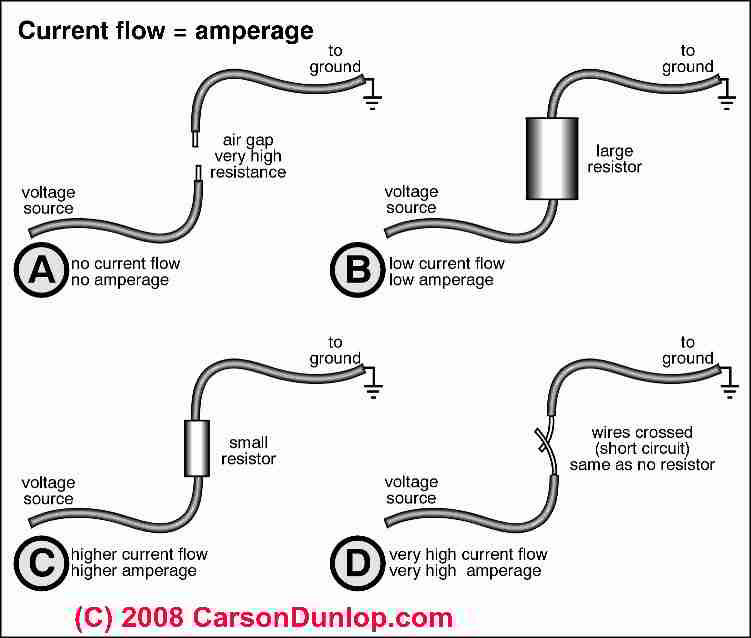
Amperage or Amps provided by an electrical service is the flow rate of "electrical current" that is available.
Mathematically, Amps = Watts / Volts. (Amps = Watts divided by Volts)
Speaking practically, the voltage level provided by an electrical service, combined with the ampacity rating of the service panel determine how much electrical demand, or in another sense how many electrical devices can be run at one time in the building. Sketch courtesy of Carson Dunlop Associates, a Toronto home inspection, education & report writing tool company [ carsondunlop.com ].
Branch circuit wire sizes and fusing or circuit breakers used set the limit on the total electrical load or the number of electrical devices that can be run at once on a given circuit.
If you have a 100 Amp current flow rate available, you could, speaking very roughly, run ten 10 amp electric heaters simultaneously. If you have only 60A available, you won't be able to run more than 6 such heaters without risk of overheating wiring, causing a fire, tripping a circuit breaker or blowing a fuse.
Also see AMPS MEASUREMENT METHODS for a description of using a clamp-on ammeter to make actual electrical usage measurements.
Ampacity, in the electrical code, refers to the current, measured in amperes, that a conductor (a wire) can carry continuously under the conditions of use without exceeding its temperature rating - in other words, the ampacity of a #14 gauge copper wire intended for residential electrical wiring is 15 Amps because that's the amount of current that the wire can carry without getting too hot.
"Too hot" means a temperature that could damage the wire insulation and thus reduce its safety.
Reader Question: What does 20 Amps mean?
What does 20 amps actually mean - Mary Riccio
Reply: ... it depends. Amps is a measure of electrical current that we elaborate here:
In a residential electrical circuit, a 20-amp rated circuit means that the electrical wire and it's overcurrent protection (fuse or circuit breaker) are rated for a total load or total current draw of 20 amps. The sum of all of the electrical current drawn by everything connected to that circuit must be 20-Amps or less - else the circuit breaker will trip or fuse will blow to prevent overheating of the wire (and a fire hazard).
The definition of AMPS or ampacity and other electrical terms can be found at InspectAPedia either by using the search box found at the top and bottom of our pages to search for DEFINITION of AMPS
Quoting from "DEFINITION of AMPS Electrical Current",
Amperage or Amps provided by an electrical service is the flow rate of "electrical current" that is available. Mathematically, Amps = Watts / Volts. (Amps = Watts divided by Volts)
Speaking practically, the voltage level provided by an electrical service, combined with the ampacity rating of the service panel determine how much electrical demand, or in another sense how many electrical devices can be run at one time in the building.
Depending on what you are looking at, 20-Amps may be the rating of a particular piece of equipment.
For example a 20-Amp circuit breaker means that that safety device will limit to 20 Amps the current drawn on the circuit that it is protecting.
If you plug three 10-amp electric heaters into that circuit and they all are running simultaneously, their combined current draw (3 x 10 = 30Amps) should trip the circuit breaker and turn off the circuit to protect it from overheating and a possible fire.
Definition of Volts or Voltage?
Volt, formally, is defined as the potential difference across a conductor when a current of one ampere dissipates one watt of power
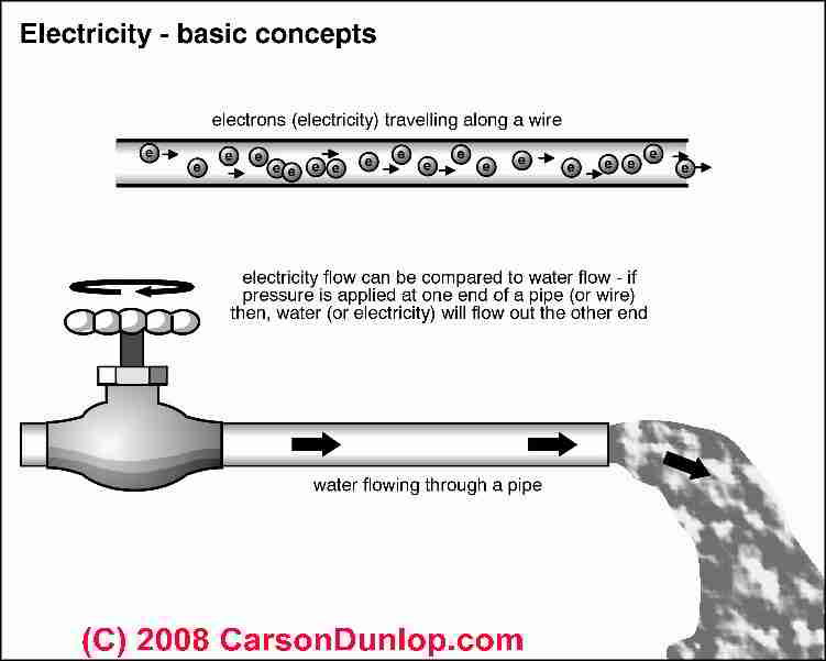
This definition is not very helpful to consumers. Using a water-in-pipes analogy, volts is analogous to water "pressure" in the electrical system. Having higher "pressure" in a pipe (or electrical conductor) means that conductor is capable of delivering more energy to the user.
Later in this article we further explain ELECTRICAL POTENTIAL.
Mathematically Volts = Watts / Amps.
(VOLTS equals WATTS divided by AMPS).
Just as a 10 gpm flow rate of water through a pipe provides half the amount of water as a 20 gpm flow rate, 10 amps of current in a conductor provides half the energy as 20 amps of current.
AMPS,as we discussed above, is a measure total current flow (or "gallons per minute" or "gpm" using the popular water analogy) available from an electrical service.
A ten-amp 240V electrical service is capable of delivering, speaking roughly, twice the energy to the end-user than a ten-amp 120V electrical service. So volts is a measure of the strength of an electrical source at a given current or amperage level.
If we bring 100A into a building at 240V, we have twice as much power available as if we bring in 100A at 120V. Volts (continuing the same water analogy) is the "pressure" in an individual electrical conductor.
Some people explain volts as similar to water pressure in a pipe, and amps as water current or total quantity flow. We discuss volts and amps below and in detail at this website. Sketch above courtesy of Carson Dunlop Associates, a Toronto home inspection, education & report writing tool company [ carsondunlop.com ].
The total current ("gpm") that will flow through a conductor is doubled if the pressure is doubled. Twice the power or energy can be delivered on a # 12 conductor by doubling the voltage and holding the current to 20 amps. Doubling voltage and also doubling the amperage will deliver four times the power or energy.
Why we need circuit breakers or fuses
In either case, if we exceed the current rating of an electrical wire, it will get hot, risking a fire. That's why we use fuse devices (or modern circuit breakers), to limit the current flow on electrical conductors to a safe level to avoid overheating and fires. - thanks to Louis Babin for technical review and edits to this text.
Is "240V" really exactly 240 Volts?:
Don't expect a "240V" circuit to provide that exact voltage level. We've already said that "120V" and "240V" are "nominal" ratings, meaning that the actual numbers may vary.
In a three phase circuit, even if you are using only two phases, the voltage between the phases is 1.732 x 120 = 207.6, or approximately 207 Volts and not 240 Volts.
n various countries the actual voltage level varies around the nominal delivered "voltage rating" and in fact depending on the quality of electrical power delivered on a particular service, voltage will also vary continuously around its actual rating.
Most (but not all) modern electrical equipment can handle small voltage variations and differences without a problem.
Sensitive electronic equipment may require that a voltage stabilizer be installed. For example a "240V" appliance can usually handle "208V" just fine.
The technical detail
of how "240V" (or 207V if you prefer) is actually delivered to a building may be a bit confusing, so let's follow this carefully.
In fact 240V delivered to a building does not mean that the individual service drop wires are carrying that voltage.
Rather, 240V in the building is obtained as follows: the two "hot legs" are on different electrical phases provided by a step-down transformer at a neighborhood utility pole or box.
Each service conductor on its own phase delivers 120V to the building.
The two (in this case) phases are arranged so that connecting a circuit across the two "hot legs" produces "240V" in for that circuit. An electrician or engineer, trained in safe volt-ohm meter (VOM) or digital multimeter (DMM) use can easily demonstrate this fact.
Connecting a voltmeter from either incoming service conductor to ground will display 120V, and connecting a voltmeter across the two incoming 120V service conductors will display approximately 208V or 240V depending on just how the supplying transformer is designed.
Technical detail about phases of electrical power: Three phase power with the star (Y-connected) connected secondary and the neutral grounded, you get 208 Volts line-to-line, and 120 Volts line-to-neutral.
With a single phase transformer (240 V secondary with a center tap and the center trap grounded), you get 120 Volts line-to-ground (neutral) and 240 Volts phase-to-phase (line-to-line). -- Thanks to N. Srinivasan for these clarifications.
Definition of Electrical Watts or Wattage?
Watts is a measure of the amount of electricity being used - a rate of electrical power consumption. Most people use a very simple mathematical formula to determine how many watts an electrical circuit can carry or how many watts an electrical device will require:
Watts = Volts x Amps
This formula shows how Watts relates to Volts and Amps. You can rearrange this equation using simple algebra or you can re-write it using Ohm's law.
(Ohms - Ω is a measure of electrical resistance, which also measures the heat that will be generated in a wire carrying a given current.)
Amps = Volts / Ohms
Given those two equations just cited, we can also write:
Watts = Volts x (Volts / Ohms),
which lets us also write Watts as
Watts = Volts 2 / Ohms
How do we calculate watts, volts, and amperage for an electrical device like an air conditioner?
Watts (W) as used in a simplified manner here and by electricians, is a measure of electrical power and is expressed by any of the formulas shown below. [All forms of power are measured in units of Watts, W, but this unit is generally reserved for real power (see definitions further below.]
W = V x I
W = I2 x R
W = V2 / R
W = Watts, V = Volts, I = Current or Amperage or Amps and R = Resistance measured in Ohms
Example: if we have a 50 watt light bulb running on a 120V circuit we can solve for the missing number, I or "Amps"
50 = 120 x I
50 / 120 = I
0.416 = I
Our 50 watt light bulb is drawing .4 amps of current.
Real Electrical Power: Accurate Energy Consumption using AC current and the Power Factor
 Reader Michael V. points out that in the above watts, volts, amps calculations, these simplified formulas are for DC voltage.
In AC electrical systems, V*I=VA not watts.
Watts is W=V*I*PF where
PF =power factor.
where
Volts x Amps = VA or Apparent Power
while
Volts x Amps X Power Factor = Watts
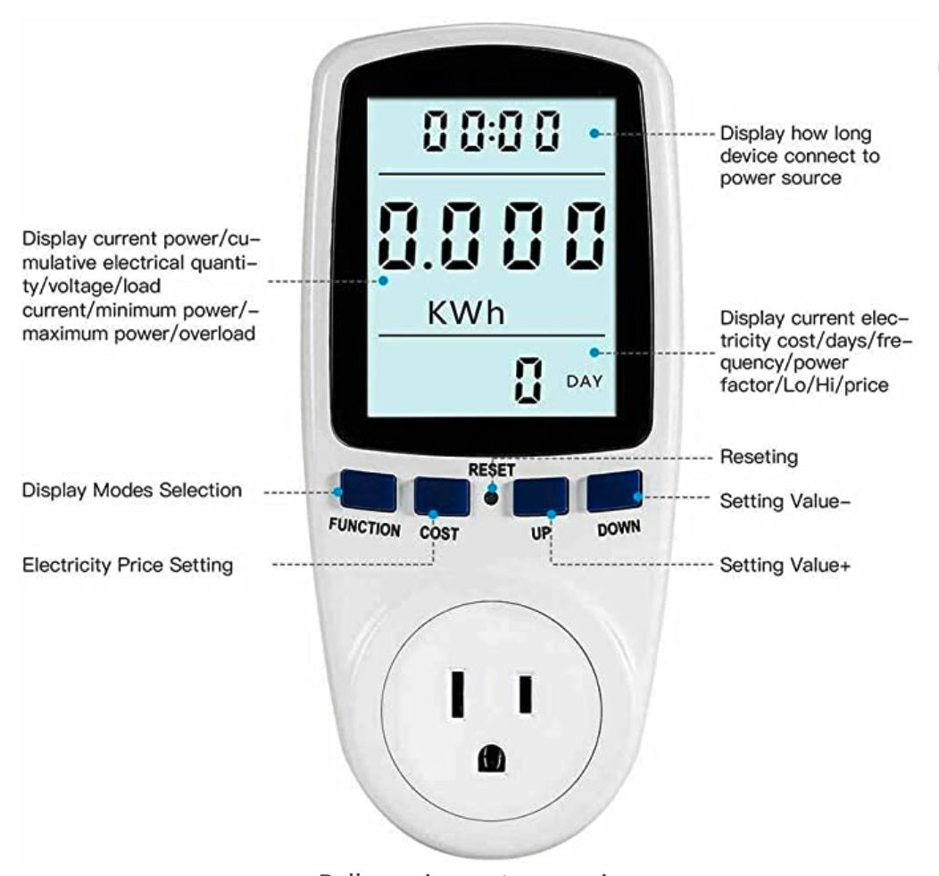
Illustration: a power meter or watt meter sold by cheapnworks at various retail vendors can be used to measure the actual current draw in amps and the actual or true watts consumed by an electrical appliance.
At SEER RATINGS & OTHER DEFINITIONS we include additional examples of calculations of electrical usage by air conditioning equipment, including how we calculate watts, volts, and amperage for an electrical device like an air conditioner.
Also see AMPS & VOLTS DETERMINATION "How to estimate the electrical service ampacity and voltage entering a building".
- In the above watts, volts, amps calculations, these simplified formulas are for DC voltage.
- In AC voltage, V*I=VA not watts.
In an AC circuit, things are more complicated. An electrical load in an AC circuit will typically use both real power - P - and reactive power - Q - (definitions below). - Watts is W=V*I*PF
where PF = power factor, as we elaborate just below.
Reader Daniel Mann adds that "Watts is correctly shown as Watts-Voltage times Current times power factor. Since power factor varies all over the place,..." [W = V x I] "perpetuates misinformation". We include additional more technical explanation of power factor, real power, apparent power, complex power, and reactive power just below.
Various sources offer further definitions of real power P, reactive power Q, complex power S, and apparent power |S|.
- Definition of PF or pf - power factor
|
The power factor of an AC electric power system is defined as the ratio of the real power flowing to the load to the apparent power, or P / S, and is a number between 0 and 1 (frequently expressed as a percentage, e.g. 0.5 pf = 50% pf). -- Wikipedia Feb 2010.
Fluke, a manufacturer of electrical test equipment, defines motor power factor as an expression of energy efficiency usually given as a percent.
Power factor (PF) is the ration of working power, measured in kilowatts (kW), to apparent power, measured in kilovolt amperes (kVA). PF expresses the ration of true power used in a circuit th the apparentpower delivered to the circuit. A 96% power factor demonstrates more efficiency than a 75% power factor. - Fluke, 202311/05, original source: www.fluke.com/en-us/learn/blog/power-quality/power-factor-formula#:~:text=Power%20factor%20(PF)%20is%20the,equipment%20during%20a%20certain%20period.
Some sources we've reviewed suggest that if you don't know the power factor or PF for an electric motor and you're trying to calculate its starting capacitor value, you can choose PF=80% or PF = 0.80 as a starting point for your calculation.
Actually when an electric motor is starting to run and is not under load, its actual PF is much lower, perhaps 0.2 - 0.3. - P - real power -
is measured in Watts - W. This is the ability of an electrical circuit to perform work. Real power is the capacity of the circuit for performing work in a particular time. -- Wikipedia Feb 2010. - Q - reactive power -
is measured in volt-amperes-reactive and varies widely. - S - complex power
is measured in volt-amperes VA. Volt-amperes or apparent power, is the product voltage V and amperes A - that is, the two measures are multiplied together. On a DC circuit VA = Watts = Real Power, as we stated earlier. On an AC electrical circuit, S, or VA, - |S| - apparent power -
is the absolute value of S. Apparent power is current X voltage in the circuit. Because there may be energy stored in the load and returned to the source (picture a rotating flywheel energized by electrical power), or due to non-linear loads on the circuit (the load is varying over time), apparent power can exceed real power in an AC electrical circuit. - Apparent power
is the product of the current and voltage of the circuit. Due to energy stored in the load and returned to the source, or due to a non-linear load that distorts the wave shape of the current drawn from the source, the apparent power can be greater than the real power. -- Wikipedia 2/19/2010
If pf - power factor - = 1, then 1 VA of apparent power transferred in a circuit will produce 1 W of real power. If pf = .5 then to produce 1 W of real power we would need to transfer 2 VA of apparent power. (1 W / .5 = 2).
It is interesting that in an electrical circuit, a load that causes a low power factor will draw more current than a load with a high power factor for the same a mount of usable or useful power actually transferred. If an electrical circuit is drawing higher current, there is more energy loss, larger transmission wires are needed, and thus costs of both the circuit and its operation are increased. Electrical engineers may design equipment to include components that improve the power factor to thus lower its operating cost.
Lots of electrical appliances include a label providing the appliance's wattage, and in the case of heating and air conditioning equipment, lots of other details are provided too.
See CAPACITOR SIZE DETERMINATION for ELECTRIC MOTORS
See ELECTRICAL POWER ANALYZERS for descriptions of power analysers used to measure electrical energy usage, consumption, efficiency
See SEER RATINGS & OTHER DEFINITIONS and
also A/C DATA TAGS for an example.
Definition of Watt Hour or Wh
What's a WattHour? Watt hours (Wh), sometimes written W.h, can measure either electrical energy produced, say by a power station, or Watts can measure the amount of electrical energy consumed (say at a light bulb or an air conditioner in our home).
For air conditioners, the A/C units' total Wh is the energy used in running the air conditioning system for an hour.
If you turn on a 100-watt light bulb for an hour, you've used 100 Wh of energy. Or if you had a one-watt bulb and lit it for an hour, it'd use 1 Wh of energy. Thank James Watt (1736-1819), credited with developing a usable steam engine, for WATT which was named for him in 1882.
Watts is an instantaneous measurement, not related to time.
To factor in time, as the electrical utility wants to do in sending us an electrical bill, the electric company's meter calculates the number. of watt hours (actually kilowatt hours) of electricity we use. If we run our 50 watt bulb for one hour, we've used 50 watt-hours. That's all the electric utility cares about.
How does a building receive 240V and 120V electrical power?
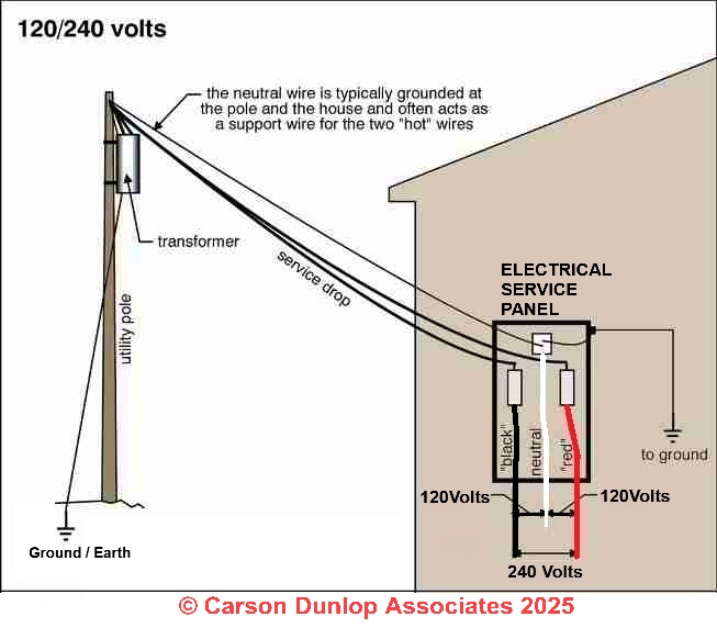
As our sketch, courtesy of Carson Dunlop Associates, shows, 240V power delivered to a building in the U.S., Canada, and Mexico, and some other locations, means that the building is receiving two 120V lines which provide 240V for circuits connected across these two incoming wires, and which provides 120V for circuits connected from either of the individual incoming lines to ground.
For heavier and commercial electrical power requirements, three and even four-phase electrical service may be delivered to a building, and in some applications, electrical equipment is designed to be fed directly by multiple phases.
You will not ordinarily see such service at a residential property, but one of the authors (DF) has encountered it in cases where there was a dental office in the basement of a home.
The dentist's x-ray equipment required three-phase power.
The tip off was the observation outside of four rather than three service conductors at the masthead, and in the main panel, the main switch was fed by three incoming service conductors rather than the usual two.
(Douglas Hansen's various publications on electricity and electrical inspections and his upcoming book point out variations of these formulae which are useful in discussing the heating of wires carrying current.)
Electrical Definitions of Wires & Components Used to Bring Electricity to a Building
We list these common electrical terms roughly in the order that they are observed, from the electrical utility company's overhead wires and pole to the building receiving electrical power to its electrical panel, and in the panel to individual circuit breakers which provide power to and protect individual electrical circuits that distribute electrical power throughout a building.
ELECTRICAL SERVICE DROP
the overhead electrical service conductors from the last electric utility pole (or other aerial support) to and including splices if any, connecting to the service entrance conductors at the building. These wires usually belong to and are the responsibility of the electric utility company.
Service-Entrance Conductors,
overhead system: the service conductors (wires) between the terminals of the service equipment (main electrical panel) and a point usually outside of the building, clear of building walls (usually the electrical masthead, visible in THIS SKETCH), where the wires are joined by tap or splice to the service drop (the wires from the utility company).
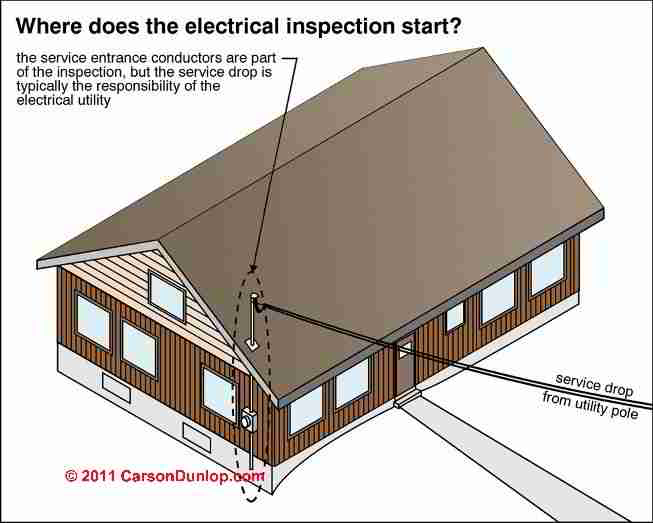
These are the electrical wires coming down the building exterior from a mast-head connection point to the electrical meter, and continuing inside to the main electrical panel or service switch. These wires normally belong to and are the responsibility of the building owner.
Service Conductors
wires connecting service point (such as the outside electric meter) to the main service disconnect (such as the main breaker in the main electrical panel). These are wires bringing electrical power from the electric meter into the electrical panel.
Service Equipment
usually the circuit breaker(s) or switches and fuses used to connect to the load end of service conductors coming to the building. This is the main electrical switch, fuse, or breaker, usually in the main electrical panel but sometimes installed as a physically separate switch before the main electrical panel.
Circuit Breaker
a device designed to open and close (turn off or on) an electrical circuit by non-automatic means (a physical toggle switch) and to open the circuit automatically (internal trip mechanism) on a predetermined overcurrent without damage to itself when properly applied within its rating. (That is, a 15A circuit breaker is expected to protect a 15A circuit, not something else).
Branch circuit
is the conductors (electrical wires, hot, neutral, ground) between the final overcurrent device protecting the circuit (a circuit breaker or fuse in the electrical panel) and the outlet(s).
A general purpose branch circuit is an electrical circuit that supplies two or more receptacles or outlets for lighting and appliances. In other words, the wires that bring power from the electrical panel to one or more points in the building where it will be used to power an light, power something plugged into an electrical outlet, or to an individual appliance.
What is the definition of Alternating Current or AC
Alternating current
is almost universally used for home electric power and is, therefore, the kind this article is primarily concerned with. In an AC circuit, the amount of voltage applied to the circuit is constantly changing from zero to a maximum and back to zero in one direction and then from zero to maximum and back to zero in the other direction.
The maximum voltage is set by the generating plant.
Because voltage is the pressure that causes current to flow, the current will also change from zero to maximum to zero and will reverse direction and repeat. The maximum amount of current, however, is determined by the load resistance and can vary as the load resistance varies.
Each complete change from zero to maximum to zero in one direction and then zero to maximum to zero in the opposite direction is called one hertz (formerly cycle).
The term hertz implies "per second." So, 60 hertz means the same as 60 cycles per second. Hertz is abbreviated Hz. Cycles-per-second, which you will still see marked in some electrical devices, is abbreviated cps.
See our ELECTRIC POWER FREQUENCY TABLE for a table showing the voltage and frequency for nearly every country in the world, provided courtesy of Paul Galow, Galow Consulting.
What is the Definition of Direct Current or DC
Direct current is most commonly found in homes in the form of electrical energy stored in batteries. In a DC circuit, the amount of voltage and the direction of application are constant.
The amount of voltage is determined by the type and size of battery. The direction of current flow is also constant and, as in AC circuits, the amount of current flow is determined by the load resistance.
Batteries convert chemical energy to electrical energy. The chemical energy can be in wet form, as in your car battery, or in dry form as in flashlight and transistor-radio batteries.
Some batteries are designed to be recharged from an AC source. The voltage from all batteries, unless recharged, will gradually decrease.
AC power can be converted to DC power for some uses in the home. The conversion is performed by a device called a rectifier or current converter.
How many Watts can a typical household electrical circuit provide?
15-Amp 120V electrical circuits
typical U.S. 120V household electrical circuit uses #14 gauge copper wire and is protected (and thus limited) by a 15-amp circuit breaker.
Such a circuit can deliver about 350 watts of electrical power to devices plugged into it, and another roughly 10 watts is consumed by the resistance of the circuit and its devices (receptacles and switches).
20-Amp 120V electrical circuits
typical U.S. 120V 20A household circuits use #12 gauge copper wire and are protected and thus limited by a 20-Amp fuse or circuit-breaker. A 20-amp circuit can provide about 2400 Watts. But as some writers have pointed out, for safety, household circuits are intended to carry less current (about 20% less) than their theoretical maximum. 80% of 2400 Watts is 1920 watts - that's about what you should expect to obtain from such a circuit.
How are we figuring these numbers? we use the formula from above, Watts = Volts x Amps and we plug in the nominal voltage and a guess at the resistance over the electrical circuit before we've plugged in anything:
Watts = 120V x 15 Amps so W = 1800 for our 15-Amp electrical circuit.
Watts = 120V x 20 Amps so
W = 2400 for our 20-Amp circuit.
Example:
If we have a 1500 Watt electric heater running on "high" and thus drawing a maximum of 1500 Watts, plugged into our 20-Amp circuit above, we've got another 420 Watts available on that circuit. So we could run maybe another four 100-watt lights on the same circuit.
The real world is a little more complex; lots of devices draw more current when they're starting-up, especially air conditioners and refrigerators.
The electrical engineer (during design) or electrician (during house wiring) choose a circuit breaker that can tolerate that temporary high current but that will trip off if high current continues to flow on the wire.
Really? Well not exactly; for safety, electrical circuits are "de-rated" to avoid overheating, so the actual maximum-recommended load in watts for the 15A and 20A circuits would be a smaller number, as Ted, an electrician, comments below.
Comment from a certified electrician:
2017/04/06 Ted, a certified electrician in Washington (USA) said:
It appears there is an error under the heading of "How many Watts can a typical household electrical circuit provide?"
A 15 amp circuit can provide more than 350 watts as you state in the first section.
In the following section on 20 circuits,you got it right for both 15 and 20 amp circuits, ie 15amps x 120volts = 1800watts.
Since residential circuit breakers are heat sensitive devices if they are loaded at 100% for an extended time they are likely to trip out. Essentially, the NEC (National Electric Code) requires circuit breakers to be derated to 80% of their rating in certain cases including heating and motor loads and "continuous loads" (those running 3 hours or more) to avoid this.
So 80% x 15 = 12 amps and 12 x 120 = 1440 watts would be max for a continuous load.
For a 20 amp circuit 1920watts as you stated [in the text above].
Determining just when a breaker will trip is difficult especially when multiple loads are on one circuit, because it depends not only on the amps the devices draw but what the duration of the draw is.
To top it all off circuit breakers are not extremely accurate on their tripping points and vary between brands.
This and other factors are why the NEC does not allow 14 ga wire to be protected at more than 15 amps, and the U.S. National Electrical Code (NEC) requires #12 to be protected at 20 amps, and #10 wire at 30 amps even though today's wiring with higher temperature rated insulations will carry somewhat more than that. It gives us some hedge factor to insure safety against overheating and fires.
Reply:
Thank you, Ted.
Readers interested in the actual UL standards for testing the current level at which an electrical circuit breaker should trip (or on older systems a fuse should blow or open) should see
UBI FPE CIRCUIT BREAKER TEST RESULTS - UBI Replacements for FPE Stab-Lok® Circuit Breaker Failure-Test Results
ZINSCO CIRCUIT BREAKER TEST REPORT - similar testing on UBI replacement circuit breakers sold for Zinsco electrical panels
There you'll see that typically we test circuit breakers to see that they respond to an overcurrent at several loiad levels. For example, following UL 489, a key test standard for electrical circuit breakers, a breaker has a specific amount of time to trip at a specific overcurrent. Lower overcurrent allows more time to trip.
What is the definition of Electrical Potential?
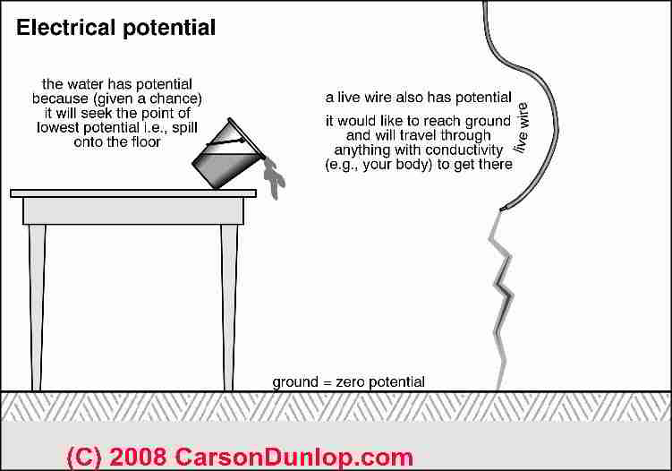
Electrical potential,
a concept used to explain ELECTRICAL VOLTAGE or volts, is illustrated at left, courtesy of Carson Dunlop Associates, a Toronto home inspection, education & report writing tool company [ carsondunlop.com ].
The word potential is used to explain that the capacity to do work is present, but not that work is necessarily being performed.
Water in the bucket in our sketch at left is a capacity to do work (move water, or exert pressure) but until water actually flows out of the bucket (say when it's tipped), no water is moving and no work is being performed.
Until something has happened, it's just a potential.
Electrical Power Phases: Differences Between Single Phase, Two Phase, Three Phase Electrical Power
Single phase vs. two vs three phase electric motors or power sources refers to the design of electric motors (such as the compressor used in heat pumps) using two different electrical power types,
- Single phase electrical power
(One live electrical wire and one neutral wire)
Some buildings electrical services provide only a single live electrical wire bringing just 120VAC to the building.
Most small electric motors are single phase 120VAC - Two phase electrical power
(Two live electrical wires, each delivering alternating current 120 electrical degrees apart)
Typical residential buildings or homes have an electrical panel that can provide either 120VAC power (using one of the incoming electrical power cables) as shown in Carson Dunlop Associates' drawing above (minor edits by InspectApedia)
Some building equipment that requires 240VAC electrical power uses both of the incoming electrical cables.
At a typical residential building with a 240-volt electrical service, a 120V circuit connects one incoming power wire through to the neutral wire (return current to the panel). Examples include lighting and electrical receptacles that can power small appliances.
At the same residential building supplied with a 240VAC electrical service, where a 240V circuit is needed, such as for larger capacity heat pumps or air conditioners, power is delivered to that circuit by using both of the incoming 120V wired circuits in the electrical panel. Connecting between them provides 240V. - Three phase electrical power - illustrated below
(Three live electrical wire, each delivering alternating current that is 120 electrical degrees apart from the other two), is a completely different topic.
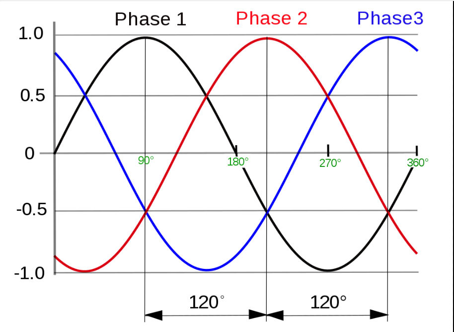
The illustration of the electrical wave forms of 3 phase current shown above is from Wikipedia's entry on the subject - https://en.wikipedia.org/wiki/Three-phase_electric_power
Smaller heat pumps and air conditioners are usually single phase while larger heat pump systems are more-often designed to use three phase electrical power and are more-often commercial heat pumps.
The main advantages of using three phase electrical power for a heat pump are:
- Electrical power to the compressor motor is more consistent in comparison with single phase power that is more vulnerable to voltage fluctuations in the electric company's power line system.
- A three phase electrical power supply is more efficient, able to transmit three times as much power than a single phase or single wire system over the transmission lines.
- For a given amount of electrical power (say measured in watts), a three phase wiring system can deliver that power using less total electrical conductor (wire) material than a single phase wire.
Phased Zone Heat Pump vs. Single vs Three Phase Electrically Powered Heat Pumps Research
- ELECTRIC MOTOR: 3-PHASE MOTOR SELECTION [Web page]
- ELECTRICAL POWER ANALYZERS
- ELECTRIC MOTOR 3-PHASE MOTOR SELECTION
- ELECTRIC MOTOR 3-PHASE TROUBLESHOOTING
- ELECTRIC MOTOR RUN DIRECTION
- ELECTRIC PANEL INSPECTION - home
- ELECTRIC POWER FREQUENCY TABLE
- GROUND SYSTEM INSPECTION - home
- SERVICE ENTRY WIRING & AMPACITY - home
- Fluke, What is the difference between single-phase and three-phase power? [Web article] Fluke Corp., Technical Support: my.fluke.com/en-US/new-request/ Tel: 0044-1603-256613 - retrieved 2025/01/05, local copy saved as Single-vs-Three-Phase-Power-Fluke.pdf
- Sprsun, Single Phase vs. Three-Phase Heat Pumps [Web article] Guangzhou SPRSUN New Energy Technology Development Co., Ltd., Tel: 0086-20-82181867 / 0086-18933985692 - Email: inquiry@sprsunheatpump.com - retrieved 2025/01/05, local copy saved as Single-vs-3-Phase-Heat-Pumps-Sprsun.pdf
Definition of Electrical Resistance & what is Ohm's Law?
Georg Ohm's Law, first published in 1827,
I = V / R
says that the current (Amps or I the formula) through a conductor (wire) between two points on a circuit is proportional to the potential difference (Voltage drop or V in the formula) across the two points and that the current (Amps) between the same two points is inversely proportional to the resistance between them (Ohms or Ω or R in the formula).
Details about electrical resistance, Ohms Law, and other versions of the Ohms Law equation above are given
at ELECTRICAL RESISTANCE, OHM's LAW
Definition of an electrical circuit?
Electrical circuits, alternating current (AC), direct current (DC), short circuits, and other basics of electrical wiring are defined further in our series of articles on electricity for homeowners starting
at ELECTRICAL CIRCUITS, SHORTS.
Definitions of Electrical Ground, Grounding Electrode, Grounding Conductor, Grounded Conductor, Ground Wire, Neutral Wire (Grounded conductor wire), Ground Rod?
How & Why It is Important to Assure Safe Electrical Grounding at a Property
Home inspector Arlene Puentes summarizes distinctions important in understanding the function of electrical grounding at a building:
- Grounding to trip the circuit breaker or blow the fuse:
Electrical grounding is necessary to protect people from electric shock by providing a good electrical path to route a faulty electrical connection (such as a short circuit) to ground (literally, to the earth) so that current will flow through and thus trip the circuit breaker or blow the fuse, safely and quickly turning off the electrical circuit.
A short circuit is one of the two ways that a fuse or circuit breaker will blow. The second is the drawing of more current (amps) than the circuit is intended to carry. - Grounding to route stray electricity
from static electricity, electrical power surges, lightning, etc. to ground. In some circumstances grounding can protect the insulation on electrical wires from damage due to high voltage. The protection against static electricity helps reduce the chances of an un-wanted spark that can cause damage to electronic components or cause an explosion of nearby combustible gases.
Stray electrical voltage can be dangerous and surprising. In 2014 the New York Times reported the electrification of an entire New York City block (surfaces, sidewalks, manhole covers, storm drain grates, even metal door knobs) due to stray voltage traced to the combination of water, salt used for melting snow and ice, and a faulty Con Edison electrical service main.
The Con Edison utility company monitors for stray voltage and detects voltage levels as low as one volt. 44 volts was measured at metal sidewalk grates in the area.
The same news article reported a death caused by stray voltage in New York in 2004. The Times cited a Con Ed 2012 survey reporting 41 cases of people being shocked and 16 cases of animals being shocked by stray voltage in that year. - Santora (2014). - Grounding to provide a normal path for electricity to flow:
energy flows in an building's electrical circuit from a power source (the utility pole through electrical panel, though building circuits and electrical devices connected to them) to the ground, to earth.
If there is no good connection to earth, electricity does not flow, though it might if you stand on wet ground and touch a live electrical wire - an action that could be fatal. Ground and neutral are related electrical terms. Neutral is used to describe the "return path" from in an electrical circuit to the electrical panel.
Inside of the main electrical panel the neutral wires are bonded to the ground wires and to a grounding conductor that connects that assembly to earth (typically through a grounding electrode or "ground rod")
Electrical Grounding Terms & Definitions
Here are some elementary electrical ground, grounding, and ground wire definitions to help us get our terms straight when discussing electrical grounds, grounding, and ground bonds.
- Ground:
means the physical earth, the soil or ground. In some countries the term earth is used and is synonymous with ground. . - Grounding electrode
or ground electrode: a metal conductor, usually a solid copper-alloy rod of specified length, driven into the ground in order to provide a point for electrical connection between the building grounding system and ground or earth. - The grounding electrode conductor
is the conductor (a wire) used to connect the grounding rod(s) to the equipment grounding conductor (the ground bus and ground wires in the electrical panel) OR to the grounded conductor (the neutral bus and neutral wires) OR to connect both of these to the grounding electrode (which is usually the case in residential electrical systems). - Grounded Conductor:
by traditional convention the grounded conductor or neutral wire is white or gray.
In an electrical circuit the grounded conductor (white or in two-phase current systems the neutral wire) normally carries electrical current between the un-grounded (hot) electrical wire and (back through the main electrical panel and grounding system) earth.
In the electrical code, a grounded conductor is one which has been intentionally grounded - connected to the earth. As reader WT Smith points out below, the grounded conductor is not necessarily synonymous with the neutral conductor. - Really? Reader W. Thomas Smith noted by comment (28 Oct 2015) the following:
Please note that referring to "Grounded Conductor" and "Neutral conductor" as synonymous is deprecated by the NEC. There are many installations where the grounded conductor is NOT a neutral conductor, including the very common 3-phase 240/120 "high leg" delta installation, where the grounded conductor is definitely not a neutral.
It is required that the "Grounded Conductor" be white or gray; the neutral conductor is not required to be this color unless it is grounded. I suggest changing the definition of "Grounded Conductor" to omit the present reference to the neutral conductor, and add a sentence or parenthetical comment (usually the neutral conductor on single-phase). - Equipment Grounding Conductor (the ground wire)
the individual wire in a (grounded) electrical circuit that is connected through the ground bus in the electrical panels and ultimately in the main electrical panel is connected to ground or earth
Details and extensive definitions of the terms used in electrical grounding & ground systems for buildings are found
at ELECTRICAL GROUND DEFINITIONS and
Also see ELECRICAL CIRCUITS, SHORTS, AC/DC.
Also see our ELECTRIC POWER FREQUENCY TABLE [PDF] for a table showing the voltage and frequency for nearly every country in the world, provided courtesy of Paul Galow, Galow Consulting. Sketch courtesy of Carson Dunlop Associates, a Toronto home inspection, education & report writing tool company [ carsondunlop.com ].
Electrical Vocabulary & Terms for Residential Electrical Inspectors
Readers of this article should see detailed in our list of RECOMMENDED ARTICLES.
- Service Drop/Service Laterals (overhead/underground from street) - Inspection not required; [note clearance/tree/condition/number of wires]
- Service Entrance (masthead, service entrance conductors, meter/meter)
- Service Voltage
- Service Amperage
- Service Equipment
- Service disconnect - main overcurrent dev.
- Service box, main panel, service panel
- Grounding equipment - rod/electrode, grounding conductor
- Grounding wire: the "ground wire," normally inactive, alternative path from various devices to ground, exercised in abnormal conditions to permit fuse to blow and reduce shock hazard
- Grounded wire: neutral wire, normally carries return current, in daily use, gives flow path of current from source to earth
- Grounding electrode conductor: "the ground wire" from service equipment to ground at water pipe or electrode(s)
- Equipment grounding conductors: "ground wires" on each branch circuit throughout the house
- Grounding: connect something to earth (0 potential)
- Bonding: joining two electrical conductors so will be at same electrical potential (FYI: gas piping not used for grounding, is bonded to the grounding system)
- Arc fault circuit interrupters: see AFCIs ARC FAULT CIRCUIT INTERRUPTERS
...
...
Continue reading at ELECTRICAL GROUND DEFINITIONS or select a topic from the closely-related articles below, or see the complete ARTICLE INDEX.
Or see DEFINITIONS of ELECTRICAL TERMS-FAQs for questions & answers about condensate pump installation, inspection, troubleshooting, & repair and that were posted originally on this page
Or see these
Recommended Articles
- AMPS VOLTS DETERMINATION - home
- DEFINITION of HEATING, COOLING & INSULATION TERMS
- ELECTRICAL INSPECTION, DIAGNOSIS, REPAIR - home
- ELECTRIC MOTOR DIAGNOSTIC GUIDE - home
- ELECTRICAL OUTLET, HOW TO ADD & WIRE - home
- ELECTRIC PANEL INSPECTION - home
- ELECTRIC POWER FREQUENCY TABLE
- GROUND SYSTEM INSPECTION - home
- SERVICE ENTRY WIRING & AMPACITY - home
Suggested citation for this web page
DEFINITIONS of ELECTRICAL TERMS at InspectApedia.com - online encyclopedia of building & environmental inspection, testing, diagnosis, repair, & problem prevention advice.
Or see this
INDEX to RELATED ARTICLES: ARTICLE INDEX to ELECTRICAL INSPECTION & TESTING
Or use the SEARCH BOX found below to Ask a Question or Search InspectApedia
Ask a Question or Search InspectApedia
Try the search box just below, or if you prefer, post a question or comment in the Comments box below and we will respond promptly.
Search the InspectApedia website
Note: appearance of your Comment below may be delayed: if your comment contains an image, photograph, web link, or text that looks to the software as if it might be a web link, your posting will appear after it has been approved by a moderator. Apologies for the delay.
Only one image can be added per comment but you can post as many comments, and therefore images, as you like.
You will not receive a notification when a response to your question has been posted.
Please bookmark this page to make it easy for you to check back for our response.
IF above you see "Comment Form is loading comments..." then COMMENT BOX - countable.ca / bawkbox.com IS NOT WORKING.
In any case you are welcome to send an email directly to us at InspectApedia.com at editor@inspectApedia.com
We'll reply to you directly. Please help us help you by noting, in your email, the URL of the InspectApedia page where you wanted to comment.
Citations & References
In addition to any citations in the article above, a full list is available on request.
- Original Authors: Al Carson, Daniel Friedman, Robert Klewitz.
Alan Carson is an ASHI Member, national home inspection educator, author and building failures researcher in Toronto, Ontario.
Daniel Friedman, an original author of this article and the editor and producer of InspectAPedia where this article now appears is an ASHI Member, first ASHI Technical Committee chairman, editor and publisher of the ASHI Technical Journal, licensed home inspector, educator, and building failures researcher in Poughkeepsie, NY. Robert Klewitz is a licensed professional engineer, a professional home inspector, an ASHI Member, and has served on the ASHI Technical Committee as well as in other ASHI activities. His practice is in Issaquah, WA. - Marc Santora & Colin Moynihan, "Stray Voltage Temporarily Electrifies Chelsea Block", The New York Times, 2/20/2014 p. A17.
- Paul Galow [Website galowconsulting.com ] - technical consultant on networking, LAN design, applications support. Galow Consulting Services [Website galowconsulting.com ] , 914-204-1749, email: paulgalow@galowconsulting.com
- Douglas Hansen, Robert Stead. Mark Cramer - technical review.
- Photographs: Daniel Friedman.
- Arlene Puentes [Website: www.octoberhome.com ] , an ASHI home inspector in Kingston, NY, suggested text on the importance of safe electrical grounding. Ms. Puentes has served as Hudson Valley ASHI (American Society of Home Inspectors) chapter president, and is active in professional education in the home inspection field. She can be contacted at ap@octoberhome.com
- N. Srinivasan, MSEE, is a senior member of IEEE with 30 years experience in the electrical industry. Mr. Srinivasan is in Vienna VA.
- Louis P. Babin generously contributed technical editing about the effects of doubling ampacity in an electrical circuit (September 2007)
- Thanks to reader Michael V. for commenting on watt, volt, amp calculations, August 2009.
- Thanks to reader Daniel Mann, P.E. for commenting on W=VxI and the power factor or PF, February 2010
- In addition to citations & references found in this article, see the research citations given at the end of the related articles found at our suggested
CONTINUE READING or RECOMMENDED ARTICLES.
- Carson, Dunlop & Associates Ltd., 120 Carlton Street Suite 407, Toronto ON M5A 4K2. Tel: (416) 964-9415 1-800-268-7070 Email: info@carsondunlop.com. Alan Carson is a past president of ASHI, the American Society of Home Inspectors.
Thanks to Alan Carson and Bob Dunlop, for permission for InspectAPedia to use text excerpts from The HOME REFERENCE BOOK - the Encyclopedia of Homes and to use illustrations from The ILLUSTRATED HOME .
Carson Dunlop Associates provides extensive home inspection education and report writing material. In gratitude we provide links to tsome Carson Dunlop Associates products and services.
 | HOME | ABOUT | ASK a QUESTION | CONTACT | CONTENT USE POLICY | DESCRIPTION | POLICIES | PRIVACY | |
| © 2025 - 1985 Publisher InspectApedia.com - Daniel Friedman | |||||||||