
InspectAPedia® FREE Encyclopedia of Building & Environmental Construction, Diagnosis, Maintenance & Repair |
Question? Just ask us! InspectAPedia
|
 Thermostatic Expansion Valves (TXVs or TEVs)
& Other Refrigerant Metering Devices
- POST a QUESTION or COMMENT about refrigeration controls: TEVs, AEVs, & others
HVACR Thermostatic Expansion Valves - TEVs:
This air conditioning repair article series explains the function and installation of all types of refrigerant metering devices, beginning with the most-common thermostatic expansion valve or TEV (or thermal expansion valve) that controls release of refrigerant into the evaporator coil of an air conditioning or heat pump system.
We define and explain other refrigeration equipment metering devices including AEVs (Automatic Expansion Valves), manually adjusted expansion valves, capillary tubes and Low Side or High Side refrigerant float valves.
Also discussed: Thermostatic expansion valve installation instructions, inspection and testing; How a TEV regulates or meters refrigerant in an air conditioner or heat pump; Guide to all refrigerant metering devices for air conditioners, heat pumps, refrigerators, freezers: TEVs, Automatic Expansion Valves AEVs, Float Valves, Manual Valves, Capillary Tubes.
InspectAPedia tolerates no conflicts of interest. We have no relationship with advertisers, products, or services discussed at this website.
- Daniel Friedman, Publisher/Editor/Author - See WHO ARE WE?
Guide to Expansion Valves for Refrigerant Metering on Air Conditioners & Heat Pumps: Definitions of AEVs, TEVs, Manual Valves, Cap Tubes

This article describes how TEVs work, where and how a thermostatic expansion valve is installed on an air conditioner or heat pump, and how the TEV may be adjusted.
[Click to enlarge any image] Schematic of a thermostatic expansion valve courtesy of Carson Dunlop Associates.
We also list possible errors in TEV installation such as improper positioning of the TEV sensor bulb.
Most of our discussion below focuses on TEVs (Thermostatic Expansion Valves) as these refrigerant metering devices are most widely used on residential air conditioners and heat pump systems.
Article Series Contents
- THERMOSTATIC EXPANSION VALVES
- THERMOSTATIC EXPANSION VALVE TEV INSTALL, DIAGNOSE, REPAIR
- TEV INSTALLATION MANUALS & GUIDES
- EEV INSTALLATION MANUALS & GUIDES
All types of refrigerant metering devices are discussed in this article. Photograph of the thermostatic expansion valve at page top is courtesy of Alan Carson, Carson Dunlop Associates in Toronto.
Definition of TEV - Thermostatic expansion valve: An air conditioner thermal expansion valve or "TEV" or just "expansion valve" (tan colored device in the page top photo) is a device located at the cooling coil and connected between the incoming liquid refrigerant line and the refrigerant inlet to the cooling coil in the air handler.
A temperature sensor mounted at the end of the cooling coil controls the rate at which the TEV releases refrigerant into the coil - hence the term "thermostatic" expansion valve.
It's an "expansion" valve because by controlling the release of refrigerant into the coil the expansion valve releases high pressure refrigerant into the low pressure environment of the cooling coil, causing the refrigerant to expand and evaporate - cooling the coil.
The actual operation of a TEV is detailed
at HOW TXVs WORK. We explain this concept in more detail
Definition of EEV - Electric exansion valve or electronic expansion valve: an air conditioner, heat pump or other refrigeration system refrigerant metering device that is controlled electronically by the combination of a separate electronic control unit, temperature sensing thermistors, pressure transducers, and an electrically-operated stepper motor that adjusts refrigerant flow rate through the valve.
Like a TEV, an EEV is also located at the cooling coil and connected between the incoming liquid refrigerant line and the refrigerant inlet to the cooling coil in the air handler.
Details are at TEV Compared to EEV ELECTRIC EXPANSION VALVES.
Other types of refrigerant expansion valves control refrigerant by various means other than sensing coil temperature.
For completeness in this article we also define and explain other refrigerant metering devices including
- AEVs (AEV_AUTOMATIC EXPANSION VALVES),
- TEV_NON-ADJUSTABLE expansion valves (actually they can be set)
- TEV_MANUAL_ADJUST expansion valves,
- CAPILLARY TUBES
- Low Side or High Side refrigerant REFRIGERANT FLOAT VALVES
Refrigerant expansion valves or metering components are used on both air conditioning systems and on heat pumps as well as on dehumidifiers; heat pumps are essentially the same in components as air conditioners except for additional control features to permit refrigerant to circulate in either direction in the system, moving heat outside (air conditioning) or moving heat inside (heat pumps).
On residential refrigerators and freezers, room and portable air conditioners, and dehumidifiers a simpler (and not adjustable)
CAPILLARY TUBES may be used for refrigerant metering.
Refrigeration Basics: Why we need a refrigerant metering device like a capillary tube or thermostatic expansion valve
Before we explain how refrigerant metering devices work in detail it's useful to get a most basic view: the refrigerant metering device provides a restriction in the flow of liquid refrigerant from the compressor/condenser into the evaporator coil.
It is this restriction that, by limiting the flow rate of refrigerant into the evaporator, allows the compressor (a pump) to raise the refrigerant pressure on the high side (condensing it into a liquid) and drop the refrigerant pressure on the low side (evaporating the liquid back into a gas in the cooling coil).
The state change (vaporization from liquid to gas in the cooling coil) is what cools the coil and thus cools indoor air air blown across the cooling coil. But that state change is not enough. To get our refrigerant gas back to a liquid state (to continue the cycle) we need to be able to raise the temperature at which the refrigerant gas will change back to a liquid. It is the high pressure provided by the compressor that accomplishes this step.
It is the flow restriction provided by a cap tube or by an expansion valve such as a TEV in the refrigerant piping system that allows the compressor pump to raise the system pressure and thus increase the temperature at which the coolant changes state. Raising the coolant temperature above outdoor ambient temperature causes heat to flow from the coolant into outdoor air.
So in sum the TEV or cap tube allows the compressor to reduce pressure on the LOW side of the metering device and raise pressure on the HIGH side of the metering device.
Expansion Valves & Thermostatic Expansion Valves for Refrigerant Metering Actually Work
 All cooling and refrigeration systems and heat pumps using refrigerant gases make use of some type of expansion valve or refrigerant metering device, of varying complexity.
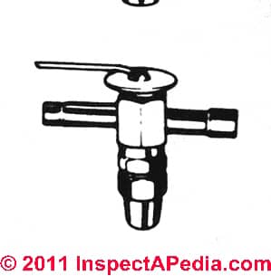
Even a simple window air conditioner or a refrigerator make use of an expansion valve [shown at left] or a small-diameter capilarry tube or "cap tube" which meters refrigerant into the cooling coil.
See details at CAPILLARY TUBE
How do these refrigerant metering devices actually work?
Step 1: Expansion valve meters liquid refrigerant into the cooling coil: Inside of the thermostatic expansion valve (TEV) or other metering device the refrigerant passing through is mostly liquid.
The refrigerant metering device is the "doorway" between the refrigeration system high side (compressor output) and low side (cooling coil interior) as it releases liquid refrigerant into the cooling coil at a controlled rate.
Step 2: Liquid refrigerant boils to a gas in the cooling coil: Inside the cooling coil, the liquid refrigerant being metered in through the TEV (or equivalent metering device) converts increasingly to a gas (it "boils" and changes state from liquid to gas) as it enters and then flows down through the evaporator coil, until the refrigerant is totally in a low-pressure, low temperature gaseous state by the time it reaches the end of the evaporator coil.
The energy absorbed by the change in refrigerant from a liquid to a gas inside the cooling coil is what absorbs sensible heat and chills the indoor air handler cooling coil so that the coil cools air blown across it.
Step 3: Low pressure refrigerant gas is drawn back into the compressor/condenser unit: This low pressure, low temperature refrigerant gas present at the end of the cooling coil or "evaporator coil" is then drawn back into the compressor via the suction line connecting the evaporator coil outlet to the compressor inlet port.
Step 4: Low pressure refrigerant gas is compressed to high temperature/high pressure gas and then condensed back to liquid refrigerant out in the compressor/condenser unit (typically located outdoors). It's the high temperature of the gas entering the outdoor condensing coil that allows heat to ultimately be transferred into outdoor air (or into water if we're using a water-based air refrigeration system).
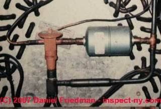
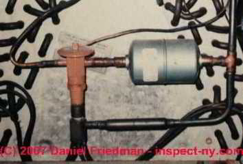
Our photo (above left shows another tan TEV.
The very thin coil of copper tubing connects the TEV to its sensor bulb that appears to be taped to the refrigerant suction line just outside of this air conditioning air handler.
The TEV shown in this photo is used on a heat pump system so it includes extra tubing so that with using a "reversing valvce" TEV can permit the refrigerant to reverse its flow of direction when changing from cooling mode (move indoor heat to outdoors) to heating mode (collect and move outdoor heat to indoors).
See details at REVERSING VALVE on HEAT PUMPS
The larger diameter copper tubing feeds liquid refrigerant into the TEV from the compressor/condenser unit (the left side of this valve) and the copper tubing on the right side of the valve loops up and into the air handler where inside the unit you'd see it entering the top of the cooling coil.
In the photo abovee you cannot see the adjustment point on the bottom of this valve. We say more about the proper position and location of this valve below.
The TEV valve maintains the pressure difference (high and low) at the entry point to the cooling coil, thus assuring that as the high-pressure refrigerant enters
the low pressure space of the cooling coil, it can "evaporate" from a refrigerant liquid to a gaseous form, thus producing the temperature drop
that cools the cooling coil itself.
The thermostatic expansion valve is a refrigerant metering control device, and it is not a control or switch which can be directly operated by the user when using an
air conditioning system, but it is a critical control needed for metering refrigerant into the cooling coil.
Exactly how the Thermostatic Expansion Valve Works to Control Refrigerant Release into the Cooling Coil (Evaporator Coil):
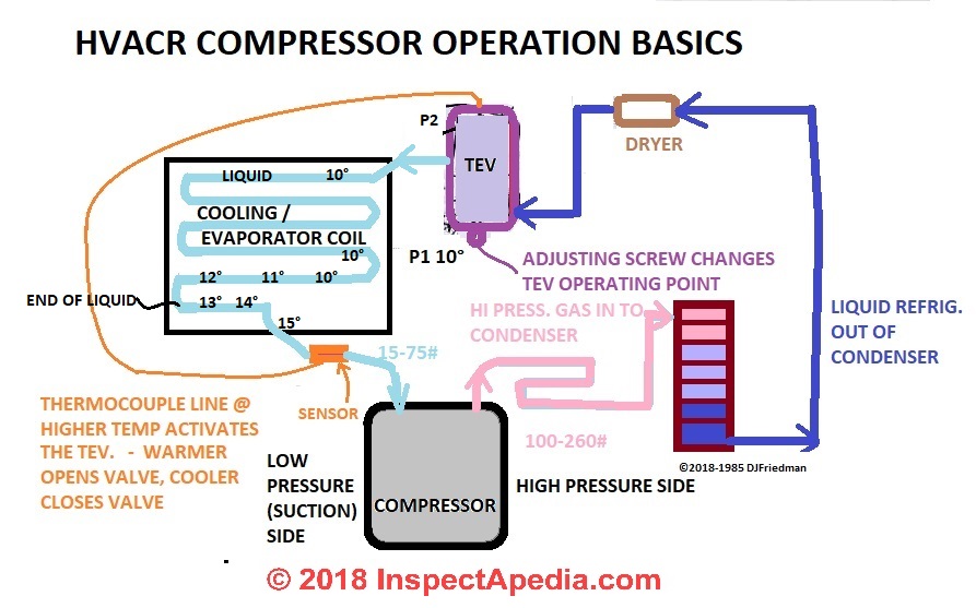
When the pressure sensed by the TEV sensor bulb (P2) is less than or equal to the pressure in the TEV bottom (P1) then this condition allows the spring inside the TEV to close the valve.
When the pressure sensed by the TEV sensor bulb (P2) [and transmitted to the TEV valve top by the sensor tubing] is greater than the pressure in the TEV bottom (P1) then this condition allows the valve to open [the cooling coil temperature is up] thus allowing more refrigerant to enter the cooling coil, thus boiling more liquid refrigerant, thus dropping the cooling coil temperature back down.
Our sketch also show the two bellows on the typical TEV control (circled in red). The bottom bellows are adjusted by the TEV adjustment screw, and the top bellows are adjusted by the temperature sensing bulb and copper tubing (purple) that connect that bulb to the TEV top cap.
The high pressure line is shown in red. A dryer is shown in green. [Click any image to see an enlarged, detailed version.]
Superheat
This definition and discussion have moved to SUPERHEAT DEFINITION
Subcooling
This definition and discussion have moved to SUBCOOLING DEFINITION
Subcooling temperatures are measured on the refrigerant line just ahead of (supplying refrigerant into) the TEV.
External Pressure Equalization type Thermostatic Expansion Valves
For completeness we include this helpful note also from Danfoss, describing the requirement for external pressure equalization type expansion valves:
Expansion valves with external pressure equali- zation must always be used if liquid distributors are installed.
Typically, the use of distributors gives a pressure drop of 1 bar across distributor and distribution tubes.
Expansion valves with external pressure equalization should always be used in refrigeration systems with small compact evaporators, e.g. plate heat exchangers, where normally the pressure drop will be greater than pressure corresponding to 2K. - Danfoss (2005)
What's the difference between a TEV (Thermostatic Expansion Valve) and an AEV (Automatic Expansion Valve) ?
 A THERMOSTATIC EXPANSION VALVE [discussed in this article] or TEV is similar to
an AUTOMATIC EXPANSION VALVE [discussed in this article] (AEV) but unlike the single-bellows internal design of the AEV, a TEV has a second bellows on the top of the valve along with a tube (purple) that attaches the TEV valve top bellows to a temperature sensing bulb mounted at the end of the cooling coil.
[Click to enlarge any image]
Our sketch, adapted from notes taken in refrigeration class back in the 1980's shows a simplified air conditioning compressor or heat pump components and the movement of refrigerant through the system.
The sensor or sensing bulb (yellow rectangle) of a TEV (purple rectangle) measures the superheat1 across the cooling coil (light blue) regardless of the actual refrigerant pressure inside the coil and uses that information to maintain the frost line at the end of the evaporator coil.
In contrast, the AEV regulates refrigerant just by pressure - it does not include the sensing bulb control.
Our TEV operation sketch (above left) illustrates the placement of the sensing bulb and its small diameter tube attached to the TEV top (purple) that controls the TEV release of refrigerant into the cooling or evaporator coil. You'll also see the temperature numbers written along the evaporator coil (blue coil at left side of sketch) showing the likely increase in temperature as we get close to the end of the evaporator coil.
Note 1: Superheat gives an indication if the amount of refrigerant flowing into the evaporator is appropriate for the load. If you want to know more about superheat see SUPERHEAT DEFINITION.
Thermostatic Expansion Valve Type & Model Identification
atReferences or Citations we provide links to examples of TEV identification catalogs and labe decoding details for several manufacturers of thermostatic expansion valves, along with company contact information. Most TEVs include a label on the expansion valve round head or attached to the valve body.
This label includes the brand and TEV model identification. You may need to consult the manufacturer's specific catalogs to decode this data, though if you are simply replacing an existing thermostatic expansion valve you can simply bring the old valve or its label information (take a photo) to your HVACR equipment distributor.
The TEV Label will identify the thermostatic expansion valve type, the evaporating temperature range in which the valve will operate, the MOP point, the refrigerant gas, a maximum test pressure, PB/MWP.
Example TEV Data Label Decoding for Danfoss: Example: TEV Model TEX2
TE = Expansion Valve
X = Refrigerant, where these refrigerant codes apply (other manufacturers may use different encoding)
- X = R22
- Z = R407C
- N = R134a
- L = R410A
- S = R404A / R507
Additional data will be encoded on some TEV components. For example the orifice assembly for a Danfoss TE/TE2 thermostatic expansion valve is stamped with:
- the orifice size
- a 3-digit date stamp: (Week + last number in the year)
- an indication of the TEV with which this orifice assembly can be used (E.g. TE12)
- and on some valves such as TE 20 and TE55, a stamp indicating the rated capacity in two temperature operating ranges (N and B)
What's the Difference Between a Thermostatic Expansion Valve (TEV) & an Electronic Expansion Valve (EEV)
A traditional TEV or thermostatic expansion valve is controlled by a spring, bellows, and pushrod. Adjustment of a TEV of that design means changing the pressure of the spring against the bellows to release refrigerant at the proper rate to maintain constant "superheat" across the coil, that is the cooling coil will be properly chilled along its entire length.
Pressure from the temperature sensing bulb connected to the top of the TEV (also called TXV by some) operates to open the valve. The spring inside the TEV pressing on the opposite side of the bellows or diaphragm plus pressure from the evaporator side (cooling coil side) of the valve operates to close the valve.
On a "balanced port" design TEV pressure of the liquid refrigerant from the condenser unit that would also tend to open the valve is cancelled out or "balanced" by the balancing port. You can recognize a traditional TEV of this design: it will have no electrical wires attached.
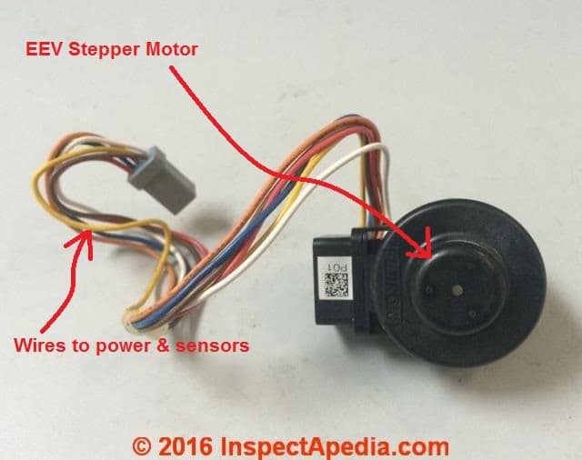
In contrast, an electronic expansion valve or EEV is a more sophisticated refrigerant metering device. A stepper motor rotates its drive shaft in one or more increments that open or close the expansion valve in small increments (as many as 1596 "steps" at 200 steps per second) as directed by an electronic controller that in turn is monitoring the system temperature.
A gear train connects the stepper motor's drive shaft to a pin that moves up or down, closing or opening the size of the port through which liquid refrigerant is being passed.
The EEV shown above, a Master-Bilt Electric Expansion Valve Model 19-13773 ser-6 is sold online by http://www.partstown.com and is also available from your local HVACR supplier.
[Click to enlarge any image]
Stepper motors in EEVs operate very precisely and their controller is smarter than I am, able to remember motor positions and to make precise and rapid adjustments to refrigerant flow, seeking the same goal: maintaining a constant superheat across the cooling coil.
The EEV stepper motor shown above is produced by Trane, EEV MOT15214 and was found for sale on eBay; available from Trane or from HVACR suppliers.
The controller for an EEV is in turn informed by one or more temperature sensors, normally a thermistor (search InspectApedia for THERMISTORS to read details) mounted in the path of air flow in the system. In some HVACR designs the EEV controller may also be informed by pressure transducers.
A change in pressure is translated by the pressure transducer to a corresponding change up or down in voltage sent to the controller.
The EEV controller uses that voltage change to obtain or actually calculate the [theoretical and close to actual] refrigerant temperature in the system and then uses that data to adjust the EEV metering of refrigerant to seek the desired temperature (or pressure).
Experts note that an advantages of EEV controllers in HVACR systems include an improved ability to protect the compressor from refrigerant floodback, precise temperature and pressure control of the system, and the ability through controller programming to design customized or special-application use of refrigerant metering and refrigeration systems.
Installation, adjustment & operation of electronic expansion valves EEVs
Excellent information about EEVs is provided by ACHR News, a publication of the refrigeration industry, including this source for the above:
- Aprea, Ciro, and Rita Mastrullo. "Experimental evaluation of electronic and thermostatic expansion valves performances using R22 and R407C." Applied Thermal Engineering 22, no. 2 (2002): 205-218.
- Choi, J. M., and Yong Chan Kim. "Capacity modulation of an inverter-driven multi-air conditioner using electronic expansion valves." Energy 28, no. 2 (2003): 141-155.
- Choi, J. M., and Yong Chan Kim. "The effects of improper refrigerant charge on the performance of a heat pump with an electronic expansion valve and capillary tube." Energy 27, no. 4 (2002): 391-404.
- Dern, Charles D. "Electronic Expansion Valves." ASHRAE journal 47, no. 3 (2005): 88.
- "Exploring EEVs: Valve technology for techs", ACHR News, June 2000, retrieved 2016/09/09, original source: http://www.achrnews.com/articles/98144-exploring-eevs-valve-technology-for-techs
Excerpt:
In previous issues of The News, electric expansion valves (EEVs) were introduced and divided into four types: pulse, analog, heat motor, and step motor. The operation of each is unique, and actual drive circuitry for each cannot be interchanged with any other type. The algorithm, or set of instructions, used to control any EEV will be similar and can be adapted for the different valves. - Lazzarin, R., and M. Noro. "Experimental comparison of electronic and thermostatic expansion valves performances in an air conditioning plant." International journal of refrigeration 31, no. 1 (2008): 113-118.
- Outtagarts, A., P. Haberschill, and M. Lallemand. "The transient response of an evaporator fed through an electronic expansion valve." International Journal of Energy Research 21, no. 9 (1997): 793-807.
- Park, Chasik, Honghyun Cho, Yongtaek Lee, and Yongchan Kim. "Mass flow characteristics and empirical modeling of R22 and R410A flowing through electronic expansion valves." International Journal of Refrigeration 30, no. 8 (2007): 1401-1407.
- Stroboulis & Robinson, Max, "Tech Tips for Thermostatic Expansion Valves", ACHR News, December 2000, retrieved 2016/09/09, original source: http://www.achrnews.com/articles/85048-tech-tips-for-thermostatic-expansion-valves. More information:
Strouboulis is application engineering manager and Robinson is market communication manager, Air-conditioning and Refrigeration Division, Danfoss Inc., Baltimore, MD. For further information, e-mail maxrobinson@ danfoss.com. Visit the company’s website at www.danfoss.com. - Tassou, S. A., and H. O. Al-Nizari. "Investigation of the effects of thermostatic and electronic expansion valves on the steady-state and transient performance of commercial chillers." International journal of refrigeration 16, no. 1 (1993): 49-56.
- Tomczyk, John, "Electronic Expansion Valves: The Basics", ACHR News, July 2004, retrieved 2016/09/09, original source: http://www.achrnews.com/articles/95056-electronic-expansion-valves-the-basics More information or reprints:
John Tomczyk is a professor of HVACR at Ferris State University, Big Rapids, Mich., and the author of Troubleshooting and Servicing Modern Air Conditioning & Refrigeration Systems, published by ESCO Press. To order, call 800-726-9696. Tomczyk can be reached by e-mail at tomczykj@tucker-usa.com. - Tomczyk, John, "Control of Electronic Expansion Valves", ACHR News, September 2004, retrieved 2016/09/09, original source: http://www.achrnews.com/articles/94207-control-of-electronic-expansion-valves
Thermostatic Expansion Valve (TEV) Installation, Inspection, Diagnosis & Testing
Thermostatic expansion valves (TEVs) are designed to meter refrigerant into the cooling coil at the proper rate. This design can keep the proper dose of refrigerant entering the cooling coil for maximum air conditioning or heat pump system operating efficiency. TEVs are similar to automatic expansion valves (AEVs) discussed below, but incorporate the signal from a temperature sensor mounted at the end of the evaporator coil
Details: If you are diagnosing a problem with an air conditioner or heat pump and the TEV appears to be involved, check the TEV installation details against the information we list in detail in a separate article at THERMOSTATIC EXPANSION VALVE TEV INSTALL, DIAGNOSE, REPAIR
Example Refrigeration Equipment Field Diagnosis & Repair: Thermostatic Expansion Valve Inspection, Testing, Experiments with TEV and Pressure Control Switch
How to Adjust the Thermostatic Expansion Valve
For most TEVs, adjusting the thermostatic expansion valve woks as follows:
- Turning the adjustment stem "clockwise" increases the superheat.
- Turning the TEV adjustment stem "counter-clockwise" decreases the superheat
Field Notes from TEV Adjustment
The following are from my [DF] notes from a refrigeration service call [1982] VERY early in my [DF] refrigeration training:.
Case outline & initial observations: Commercial cooler running too warm - (WACOOP), hermetically sealed compressor, Kramer W14, unknown refrigerant (thought from a label maybe it should be R22 but someone may have charged with R12), cooler running too warm, need to diagnose cooling coil and fan operation and control settings on an old, used cooler just brought in. Very common on old equipment like this: no labels, no data tags, not much information at all.
Fanco refrigerant pressure switch: found set at 35# and 10# differential, connected improperly to the low side service port, cannot fully shut off the service port as a result - maybe leaking?
Compressor pump: running continuously.
Ambient temperature about 90 DegF; R12 in my service canister is at 100 psi static.
Low side refrigerant pressure: measured 40 psi. If there is R12 in the system I'd expect about 45 deg. temp at proper charge, and if R22 in the system I'd expect about 20 degF temp at proper charge and operation. But there were NO frost lines on the equipment, so I know that there is little or no liquid refrigerant and the system is operating at about 45 degF so must be filled with R12.
Actions and Tests:
Set the TEV 8 quarter turns more open - out and down, to see what happens.
With the fan off the Low Side goes to 25 psi and 25 degF.
The frost line moved at least to the se3nsor bulb and the pump (compressor) shut off. The low side pressure went up to 36 psi and then the pump restarted. This is telling me what the pressure control switch is doing.
Further actions and observations:
Opened the TEV 1/4 turn more to see the effect.
System shut off at 23# and came back on at 37#
Turned the blower cooling fan back on since the Dx was iced coil. Low side went up to 50, then dropped to 39# and stabilized.
Kept a series of observations from 10:55 PM to 12:42 AM (service call made during hours the business was closed to avoid disruption)
5 then 9 more turns opening the TEV, low side up to 75# & can see gas in the SIGHT GLASS in the refrigerant line - this is "wide open" TEV setting
9 turns closing down the TEV to almost shut - so there are about 10 turns from wide open to fully shut on this TEV. At 9 turns towards shut from wide open, the low side pressure falls FAST!
9 turns back open at the TEV confirms gas bubbles again in the sight glass and 70# pressure.
Closed the TEV completely (about 9+ turns to the right or "up" or "in"). Suction lines closed, no gas in the sight glass, rapid low side pressure drop to 26#, compressor turns off at 20#.
I am convinced the pressure control switch is working properly, that is it does what it's pressure settings say it should be doing.
Set the TEV to 12 1/4-turns (in other words 3 full turns) open from fully shut. Suction line very cold, low side goes to 30#. 2 more turns open, low side goes up to 34#.
Finally decide to run the system with the TEV open 3 quarter-turns (about 3/4 of one turn) from fully shut. The system stabilizes with the cooler (a refrigerator) in the mid to upper 40's, no more oscillating, no coil frosting.
If I set the cut-in pressure way down the cooling coil ices over and the compressor will run continuously without cooling anything. See frost moving down the low side line. So that's not the right "fix".
I could set the pressure switch to 12.5 psi, left the TEV alone, and got the cooler down to our target of 32 degF.
The HI event sets the defrost cycle by setting the cut-in. The low event sets the cutout and therefore the lowest temp we will reach. A bigger low event means a lower target temperature, but the risk is that if you set it too low the compressor will run continuously and ice up the coil without ever running a defrost cycle.
The TEV seemed to be sometimes sticking. The low side pressure would hang at 28# or rise only very slowly as if the TEV was not opening when I expected it to. Have to be sure the blower fan is also running when checking this performance.
Final resolution of the cooler operation troubles:
Ultimately I replaced the TEV with a Singer TXV223FA 1/2 with a TE value of 9 (heat delta), installed a filter dryer (#082 PN 2003), set the pressure control to 35# on and 20# off. adjusted the system to get NO frost on the suction line near the compressor. Final pressure switch settings were 33# and 18# hi and low. We were able to get the cooler, charged with R12, to hold a stable 34 degF at cutoff, rising to 39 degF at which point the compressor would cut back on.
Guide to Other Types of Refrigerant Metering Devices besides TEVs: AEVs, Cap Tubes, Float Switches, Manually Adjustable Refrigerant Metering Valves
Capillary Tubes - a simpler method for metering refrigerant
Separately at CAPILLARY TUBES. we explain how capillary tubes are used to meter refrigerant in air conditioners, dehumidifiers, refrigerators, & freezers. We include a description of the operating properties of cap tubes, we contrast their use and function with thermostatic expansion valves or similar devices, and we include cap tube problem diagnostic tips for air conditioning service and repair purposes.
What's the Difference Between a Refrigerant Capillary Tube or "Cap Tube" and a Refrigerant Expansion Valve or TEV / AEV?
 As we detail at CAPILLARY TUBES, compared with a capillary tube, the TEV or AEV adds a level of control - the TEV / AEV or even float valves and manually and adjustable refrigerant metering valves can open or shut in response to an attached bulb or pressure sensor (AEVs) which actually monitors temperatures in the refrigerant tubing.
Capillary tubes are found on residential refrigerators, dehumidifiers, and many window air conditioners. TEVs are found on larger air conditioners and central air conditioning systems where more control is needed.
In our TEV sketch (left) the small diameter tube at the top of the thermostatic expansion valve is connected to a temperature sensing bulb (not shown) that is located at the outlet end of the cooling or evaporating coil in the air handler.
The tubing at the left and right permit liquid refrigerant to flow into the valve from the compressor/condenser and, metered by the TEV, onwards into the evaporator coil. The large nut on the bottom of this TEV covers an adjustment screw that can change the latent heat settings and thus the behavior of the valve once it is installed. (Normally you should leave the valve at its factory setting.)
"Non-Adjustable" & Manually Adjustable Expansion Valves: How they are Set
Singer and other manufacturers point out that TEVs are adjusted at the factory before shipment. The factory setting of a thermostatic expansion valve is printed on a label found on the head of the valve and for most installations the factory superheat settings should be left alone.
How & When to set "Non-Adjustable" Thermostatic Expansion Valves
Non-adjustable TEVs (such as Singer TEV models 226, 326, 426) can actually be adjusted before the valve is installed, by turning an adjustment screw through the valve outlet opening. Once these valves have been installed, however, adjusting the valve would require removing it from the system, thus also requiring an evacuation and recharge of system refrigerant - not something to do casually.
How to Set Manually Adjustable Thermostatic Expansion Valves
Manually adjustable TEVs permit the device to be set to continuously maintain the proper refrigerant level entering the evaporator coil or cooling coil. Automatic expansion valves are discussed below.
- Adjustable TEVs include an adjusting stem that can be turned with a screwdriver. Some valves may require that a covering cap be first removed to provide access to the adjusting screw or stem. On Singer adjustable TEVs (other controls will be similar),
- Turn the adjusting screw only one turn at time to prevent over adjustment. We make a tiny scratch on the valve bottom at the start end of the screw slot so that we can keep careful track of how far a screw has been turned.
- To increase the superheat setting, turn the TEV valve stem clockwise. When you turn the valve stem "in" or "clockwise" you are increasing pressure on the spring - the bellows will need more pressure to force the needle off of the seat, so the frost line will recede (less refrigerant is passing through) - and vice versa.
- On a Danfoss™ T / TE2 expansion valve, 1 complete rotationof the adjusting spindle will provide about 4K (°C) in the superheat at an evaporating temperature of 0°C
- On a Danfoss™ TE5 exapansion valve one turn of the adjusting spindle provides about 0.5K in superheat at an evaporating temperature of 0°C
- On a Danfoss™ TUA or TUB expansion valve one turn of the spindle produces a temperature change of about 3K in superheat at an evaporating temperature of 0°C
- To decrease the superheat setting, turn the TEV valve stem counter-clockwise. Normally the TEV is set for 7 to 12 degrees of superheat across the cooling coil (evaporator coil).
- Allow the air conditioning or heat pump system to stabilize for half an hour after each adjustment turn before trying to adjust the valve further.
Automatic Expansion Valves for Refrigerant Metering - AEVs
 Automatic expansion valves used to meter refrigerant into a cooling system are similar to Thermostatic Expansion Valves (discussed above) but AEVs do not use a temperature sensing device mounted on the cooling coil.
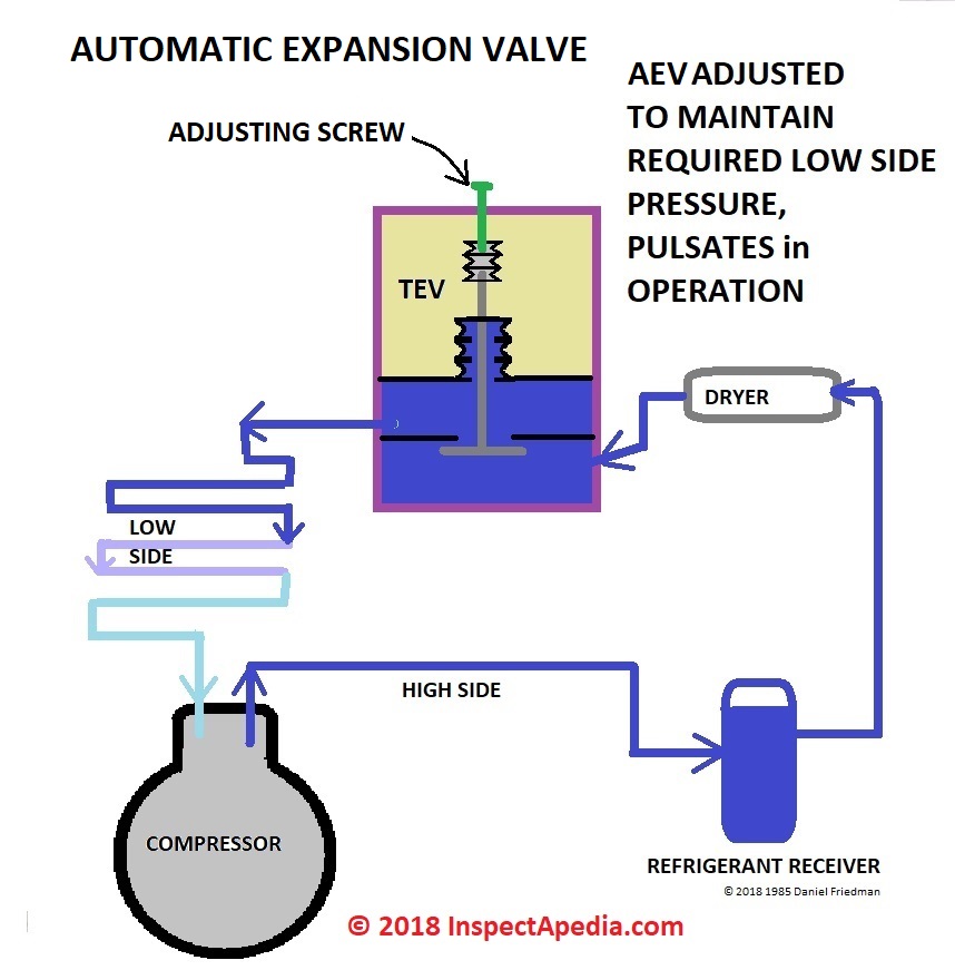
Rather the automatic expansion valve is mechanically set by adjusting a screw that presses a spring that presses a diaphragm that regulates refrigerant release by constant pressure.
[Click to enlarge any image]
Automatic Expansion Valve (AEVs) (center of sketch at left)
In normal operation the adjusting screw (see our sketch) is set to maintain a given pressure on the low side of the refrigeration system.
During system operation the Automatic Expansion Valve pulsates - it opens and closes constantly.
Diagnosing AEV trouble: AEVs can close up (stop working) if you add extra load to the refrigeration system - because of the extra heat load - the system will appear to run as if it were short-charged. So automatic valves are used on systems where the load is more consistent.
[Click any image to see an enlarged, detailed version]
Automatic Expansion Valves (AEVs) are repairable. These devices are most often used on constant-load refrigeration systems such as restaurant coolers.
Avoiding Trouble with Adjustable Expansion Valves
Watch out: on AEVs that have an accessible adjusting screw, it's important to keep the protective rubber cap on the device. The cap provides insulation to prevent the water produced during TEV defrost cycle from seeping into the bellows of the device where it can freeze and rupture the bellows.
Also review our advice on Adjusting the Thermostatic Expansion Valve - if you don't allow sufficient time for the system to stabilize after each turn of the TEV adjusting screw you can easily over adjust and lose control of the system.
Commercial Refrigeration Equipment Devices for Metering Refrigerant: Low Side & High Side Floats
On many commercial air conditioning and larger refrigeration systems you may see a large canister on top of the equipment (sketch at above) that acts as a refrigerant reservoir or receiver. Vapor exits at the top of the reservoir and liquid refrigerant enters lower in that canister, typically from a side port.
A float with a needle valve allows liquid refrigerant to enter the canister to replace refrigerant that has boiled off and exited out of the upper valve as a gas. Float type refrigerant metering systems are used on refrigeration systems in which the evaporator is the "flooded type" - always kept full of refrigerant down to the end of the coil.
Low-Side Float Refrigerant Metering Devices
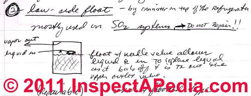
Low-side float refrigerant metering devices, installed on the low-pressure side of the refrigeration system, are used mostly on SO2 refrigerant systems.
A low-side float receiver will show up as a large canister atop a refrigerator that uses this type of refrigerant.
Inside the low side float refrigerant metering device a float combined with a needle valve permits liquid refrigerant to enter to replace refrigerant as it boils off and exits out of the upper exit valve - shown at the top left of my class-notes sketch.
Watch out: If arefrigeration system is using SO2, experts recommend that you do not attempt to repair this device.
[Click any image to see an enlarged, detailed version]
High-Side Float Refrigerant Metering Devices
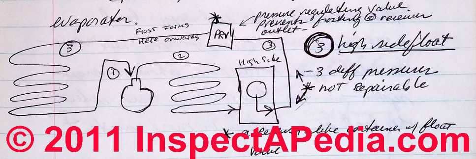
A high side float refrigerant metering device is illustrated in our sketch.
As our drawing notes explain, the float is located on the HIGH side of the system. A high-side float-metered refrigerant system will show three different refrigerant pressures:
- Operating or release pressure between the high side float metering device and the inlet to the PRV
- Low side pressure on the PRV outlet side and between the PRV outlet and the compressor motor inlet.
- Compressor outlet pressure betrween the compressor outlet and the High Side Float Device Inlet.
A pressure-regulating valve prevents frosting at the receiver outlet (PRV in in the sketch at top center).
Frost will appear on the refrigerant tubing from the outlet side of the PRV (pressure regulating valve) onwards towards the compressor.
With proper refrigerant metering frost will disappear from the refrigerant tubing before the tubing enters the compressor motor.
Watch out: Like the low side float refrigerant metering device, a high-side float-type refrigerant control is not field-repairable.
Thermostatic Expansion Valves TEVs Installation Manuals & Guides
- Carrier THERMOSTATIC EXPANSION VALVE KIT INSTALLATION INSTRUCTIONS [PDF] R-410A, (2002) retrieved 2021/07/27 original source: https://resource.carrierenterprise.com/is/content/Watscocom/carrier_ksatx0501pur_article_1422491346072_en_ii
- Emerson, TRAE THERMAL EXPANSION VALVE INSTALLATION INSTRUCTIONS [PDF] (2013) EmersonClimate.com/FlowControls Technical Support: 1-866-625-8416 retrieved 2021/07/27 original source: https://climate.emerson.com/documents/trae-thermal-expansion-valve-instructions-en-us-1594742.pdf
- Goodman TXV INSTALLATION INSTRUCTIONS [PDF] (2012) Goodman Manufacturing Co., 5151 San Felipe, Suite 500, Houston, TX 77056 USA Web:
www.goodmanmfg.com -or- www.amana-hac.com
Includes a helpful expansion valve troubleshooting chart. - Goodman EXPANSION VALVE KITS TX3N2, TX3N4, TX5N2, TX5N4 INSTRUCTIONS [PDF] (2004) Op. Cit.
- ICP International Comfort Products THERMOSTATIC EXPANSION VALVE INSTALLATION MANUAL [PDF] International Comfort Product, LLC
Lewisburg, TN 37091 USA for NAEA4 (R−410A) & NAEA2 (R−22)
TXV Conversion Kits for Piston Coil to TXV Coil - Johnson Controls Unitary Products R-410A OUTDOOR SPLIT-SYSTEM AIR CONDITIONING INSTALLATION MANUAL [PDF] (Home Depot)
- IngersollRand R-22 TXV KIT INSTALLATION INSTRUCTIONS [PDF] Ingersoll Rand 6200 Troup Highway Tyler, TX 75707 USA
- Ingersoll Rand, R-410A TXV Kit INSTALLERS GUIDE [PDF] (2018) Ingersoll Rand 6200 Troup Highway Tyler, TX 75707 USA
- Manitowoc TXV INSTALLATION GUIDE [PDF] (2008) Manitowoc Foodservice 2100 Future Drive Sellersburg IN. 47172 USA Phone 1-800-367-4233 Web Site - www.manitowocfsg.com original source: https://www.manitowocice.com/asset/?id=hczdg
- Nordyne THERMAL EXPANSION VALVE TXV KIT INSTALLATION INSTRUCTIONS [PDF] (2009) Nordyne, O'Fallon MO, USA
- Parker / Sporlan THERMOSTATIC EXPANSION VALVE INSTALLATION MANUAL [PDF] (2012) Parker Hannifin LTd., Parker Hannifi n Ltd Climate and Industrial Controls Group Refrigeration and Air Conditioning Europe Cortonwood Drive, Brampton Barnsley S73 OUF - United Kingdom Tel: +44 (0) 1226 273400 Fax: +44 (0) 1226 273401 racecustomerservice@parker.com www.parker.com/race - the company has offices world-wide.
- Sanhua TXVH THERMOSTATIC EXPANSION VALVE INSTUCTIONS [PDF] (2018) Sanhua, Seb: Sanhuasa.com
- York CU-MODELS TXV INSTALLATION MANUAL [PDF] (2016) York International Corp. 5005 York Drive Norman, OK 73069 USA
...
Reader Comments, Questions & Answers About The Article Above
Below you will find questions and answers previously posted on this page at its page bottom reader comment box.
Reader Q&A - also see RECOMMENDED ARTICLES & FAQs
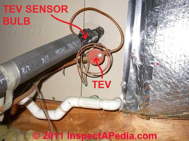
On 2021-07-27 by (mod) - proper mounting of the sensor bulb & routing of the small diameteter tube between the TEV and the sensor bulb
@Mauro,
Thanks that's an interesting question;
In the cap tube installation instructions and schematics I've seen the installation position that is most critical is the location of the bulb, but I think the manufacturer is also trying to get us to route the tubing on the smoothest, most-direct route without bending it back over itself - causing a crimp and a blockage or leak.
Here are excerpts from example installation details for the sensor bulb for a TEV used with R410-A from Ingersoll Rand - you can find that instruction guide above on this page.
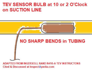 Make contact tight between the suction line and the sensor bulb
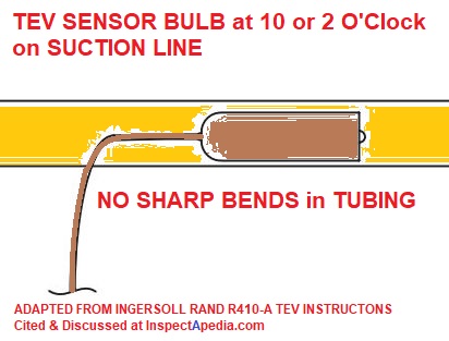
- Clean the suction line thoroughly before clamping the bulb in place.
- Bulb has to be mounted in tight contact with pipe. (TIP: Shine a flashlight between bulb and suction line, realign the bulb if light is visible.)
- Align the bulb with copper refrigerant gas line and position at 10 or 2 o’clock.
- Pull the bulb strap tight around the copper refrigerant gas line and bulb before tightening the screw.
- After tightening, it should not be possible to move the bulb by hand.
...
- Orient the sensing bulb with the tube exiting out the top to the vapor line extension onto a straight section of the refrigerant gas line as shown in Figure 9. [Shown here as adapted - Ed.]
- Use the supplied TXV bulb strap shown in Figure 5 to secure the bulb in place. In some cases, the bulb strap is required when the new bulb size is different from the existing sensing bulb.
- The entire length of the bulb must be in firm contact with the refrigerant gas line. The remote bulb tubing must not be allowed to touch a surface colder than the remote bulb location. The remote bulb tubing must be isolated from rubbing all other components. - Ingersoll Rand R410-A TEV Instructions, cited above.
Watch out: at TEV SENSOR BULB LOCATION you will see that various manufacturers give different sensor bulb locations, and that the locations vary also depending on the size or diameter of the suction line. But our point here is that these instructions detail the routing of the small diameter copper tubing between the sensor bulb and the TEV and they specifically have you avoid making a sharp bend in the tubing.
Staebler, a Philco engineer, in a really helpful 1972 article never mentions a requirement for directional orientation so I suspect my bending caveat is what's left.
- Staebler, Lloy A., THE CAPILLARY TUBE AND ITS APPLICATION TO SMALL REFRIGERATING SYSTEMS [PDF] (1972, 2009) Refrigeration Service Engineers Society. RSES
PO Box 248
Arlington Heights, IL 60006-0248 USA, TelL: 800/297.5660 Web: https://www.rses.org/
Website excerpt: RSES is the leading education, training and certification preparation organization for HVACR professionals. RSES publishes various comprehensive industry training and reference materials in addition to delivering superior educational programs designed to benefit HVACR professionals at every stage of their careers through instructor-led training courses, online training for HVAC, educational seminars, interactive CD and DVD products, industry-related reference manuals, and helpful technical content through Service Application Manual chapters, the RSES Journal, the RSES Journal archives and feature articles, as well as web-exclusive features.
I'm looking into this further.
See THERMOSTATIC EXPANSION VALVE TEV INSTALL, DIAGNOSE, REPAIR where we also address AEVs, float valves, manual and automatic expansion valves, etc.
Also see CAPILLARY TUBES as the same routing concerns would pertain.
On 2021-07-27 by Mauro
Hello, very good this page of yours, I was always curious to know why the expansion valve manufacturers ask to install the bulb with its capillary facing in the direction of the gas flow, can you tell me why?
thermolondri@gmail.com
...
Continue reading at THERMOSTATIC EXPANSION VALVE TEV INSTALL, DIAGNOSE, REPAIR or select a topic from the closely-related articles below, or see the complete ARTICLE INDEX.
Or see THERMOSTATIC EXPANSION VALVE FAQs - questions & answers posted originally at the end of this page
Or see these
Recommended Articles
- CAPILLARY TUBES
- CONTROLS & SWITCHES, A/C - HEAT PUMP
- LOST COOLING CAPACITY - air conditioning "running" but not enough cool air, or no cool air
- PRESSURE CONTROLS & SAFETY SWITCHES - home
- REVERSING VALVE on HEAT PUMPS
- REFRIGERANT PRESSURE READINGS & CHARTS - home
- THERMOSTATIC EXPANSION VALVES - home
- THERMOSTATIC EXPANSION VALVE TEV INSTALL, DIAGNOSE, REPAIR
- THERMOSTATIC EXPANSION VALVE TEV STICKING REPAIR
Suggested citation for this web page
THERMOSTATIC EXPANSION VALVES at InspectApedia.com - online encyclopedia of building & environmental inspection, testing, diagnosis, repair, & problem prevention advice.
Or see this
INDEX to RELATED ARTICLES: ARTICLE INDEX to AIR CONDITIONING & HEAT PUMPS
Or use the SEARCH BOX found below to Ask a Question or Search InspectApedia
Ask a Question or Search InspectApedia
Questions & answers or comments about refrigeration controls: TEVs, AEVs, Capillary Tubes, Float Valves, & Other Refrigerant Controls
Try the search box just below, or if you prefer, post a question or comment in the Comments box below and we will respond promptly.
Search the InspectApedia website
Note: appearance of your Comment below may be delayed: if your comment contains an image, photograph, web link, or text that looks to the software as if it might be a web link, your posting will appear after it has been approved by a moderator. Apologies for the delay.
Only one image can be added per comment but you can post as many comments, and therefore images, as you like.
You will not receive a notification when a response to your question has been posted.
Please bookmark this page to make it easy for you to check back for our response.
IF above you see "Comment Form is loading comments..." then COMMENT BOX - countable.ca / bawkbox.com IS NOT WORKING.
In any case you are welcome to send an email directly to us at InspectApedia.com at editor@inspectApedia.com
We'll reply to you directly. Please help us help you by noting, in your email, the URL of the InspectApedia page where you wanted to comment.
Citations & References
In addition to any citations in the article above, a full list is available on request.
- Danfoss Thermostatic Exansion Valves, Type TE / TE2, Danfoss Refrigeration & Air COnditioning Division, Danfoss Ltd., Oxford Rd., Denham, Bucks UB9 4LH, UK, Tel: 0879 241 7041, Email: uk.refrigeration.sales@danfoss.com Website: www.danfoss.co.uk - retrieved 8/31/2014, original source op cit.
- Danfoss Thermostatic Expansion Valves, Fitters Notes, RZ1AH202 → DKRCC.PF.A00.A1.02 / 520H0337, Danfoss A/S (2005),
- Sporlan Thermostatic Expansion Valves Identification [Guide], Bulletin 210-60 (1994), Danfoss Refrigeration & Air COnditioning Division, Danfoss Ltd., Oxford Rd., Denham, Bucks UB9 4LH, UK, Tel: 0879 241 7041, Email: uk.refrigeration.sales@danfoss.com Website: www.danfoss.co.uk - retrieved 8/31/2014, original source op cit.
- [1] "Thermostatic Expansion Valve Installation Instructions", Singer Controls Division, Schiller Park IL, 1979 parts brochure
- [2] Christopherson, Norm, "Preventing Premature Compressor Failures, An Ounce of Prevention for Years of Service", web search & reader TN Goose referral, 08/12/2011, original source: http://www.hvacfun.com/a-once-prevent-years-service-comps.htm
- Emerson Climate Technologies, "Quick Facts: Superheat and Subcooling", (2005) Flow Controls Division of Emerson Climate Technologies (formerly Alco Controls), Website: www.emersonclimatecontractor.com, retrieved 7/22/2014, original source http://www.achrnews.com/articles/quick-facts-superheat-and-subcooling
- Modern Refrigeration and Air Conditioning, A. D. Althouse, C.H. Turnquist, A. Bracciano, Goodheart-Willcox Co., 1982
- Principles of Refrigeration, R. Warren Marsh, C. Thomas Olivo, Delmar Publishers, 1979
- Refrigeration and Air Conditioning Technology, 5th Ed., William C. Whitman, William M. Johnson, John Tomczyk, Cengage Learning, 2005, ISBN 1401837654, 9781401837655 1324 pages
- In addition to citations & references found in this article, see the research citations given at the end of the related articles found at our suggested
CONTINUE READING or RECOMMENDED ARTICLES.
- Carson, Dunlop & Associates Ltd., 120 Carlton Street Suite 407, Toronto ON M5A 4K2. Tel: (416) 964-9415 1-800-268-7070 Email: info@carsondunlop.com. Alan Carson is a past president of ASHI, the American Society of Home Inspectors.
Thanks to Alan Carson and Bob Dunlop, for permission for InspectAPedia to use text excerpts from The HOME REFERENCE BOOK - the Encyclopedia of Homes and to use illustrations from The ILLUSTRATED HOME .
Carson Dunlop Associates provides extensive home inspection education and report writing material. In gratitude we provide links to tsome Carson Dunlop Associates products and services.
 | HOME | ABOUT | ASK a QUESTION | CONTACT | CONTENT USE POLICY | DESCRIPTION | POLICIES | PRIVACY | |
| © 2025 - 1985 Publisher InspectApedia.com - Daniel Friedman | |||||||||