 Capillary Tube Refrigerant Metering Devices
Air conditioner, heat pump, refrigeration cap tubes
- POST a QUESTION or COMMENT about cap tubes or capillary tubes used for refrigerant metering in HVACR equipment
Air conditioner & refrigeration equipment capillary tubes:
This air conditioning repair article explains the function and installation of capillary tubes or "cap tubes" used to control or meter the release of refrigerant into the evaporator coil of an air conditioning or heat pump system, home refrigerator, freezer, dehumidifier, or other refrigeration equipment of up to 6 tons in cooling capacity. We define and explain the function, installation, servicing, and replacement procedures for capillary tubes.
InspectAPedia tolerates no conflicts of interest. We have no relationship with advertisers, products, or services discussed at this website.
- Daniel Friedman, Publisher/Editor/Author - See WHO ARE WE?
Guide to Air Conditioner, Heat Pump, & Refrigeration System Capillary Tubes: How Does a Capillary Tube Work to Meter Refrigerant?
Here we explain how capillary tubes are used to meter refrigerant in air conditioners, dehumidifiers, refrigerators, & freezers.
We include a description of the operating properties of cap tubes, we contrast their use and function with thermostatic expansion valves or similar devices, and we include cap tube problem diagnostic tips for air conditioning service and repair purposes.
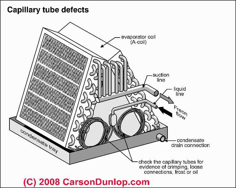
Our page top sketch of common visibly detectable capillary tube defects is provided courtesy of Carson Dunlop Associates as is the cap tube explanation just above.
Article Contents
- DEFINITION of CAPILLARY TUBE for HVACR equipment
- CAPILLARY TUBE DIAMETER & LENGTH SET ITS REFRIGERANT METERING RATE
- DIFFERENCE BETWEEN a CAPILLARY TUBE and A TEV THERMOSTATIC EXPANSION VALVE
- DIAGNOSE & REPAIR REFRIGERANT METERING DEVICES like Cap tubes or TEVs
- CAPILLARY TUBE REPLACEMENT PROCEDURE
- SET MANUAL or "NON-ADJUSTABLE" CAPILLARY TUBES
...
What is a "Capillary Tube" used on Air Conditioners, Heat Pumps, Refrigeration Equipment?
Capillary tubes are the most simple refrigerant metering device used in air conditioners and other refrigeration equipment. There are no moving parts, just a very small diameter tube that meters refrigerant from the high side into the cooling coil.
Systems using a cap tube do not have a liquid refrigerant receiver and the amount of refrigerant charge must therefore be exact.
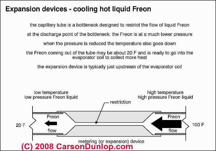
Our sketch simplifies the concept of the an expansion valve down to a simple capillary tube - this is the simplest possible refrigerant metering device. Sketch courtesy of Carson Dunlop Associates, a Toronto home inspection, education & report writing tool company [ carsondunlop.com ].
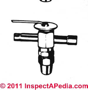
A simple capillary tube (sketch at left) or a more sophisticated and typically adjustable thermostatic expansion valve (shown in our sketch at below and sometimes improperly called thermal expansion valve) valve maintains the pressure difference (high and low) at the entry point to the cooling coil, thus assuring that as the high-pressure refrigerant enters the low pressure space of the cooling coil, it can "evaporate" from a refrigerant liquid to a gaseous form, thus producing the temperature drop that cools the cooling coil itself.
Synonyms for devices similar to capillary tubes and used to meter refrigerant on some air conditioners, heat pumps, and other refrigeration equipment are "refrigerant orifice", "refrigerant actuator", or even "refrigerant metering piston".
None of these refrigerant metering devices handle a wide range of on-site conditions and refrigerant charge levels as well as THERMOSTATIC EXPANSION VALVES.
TEVs adjust the level of refrigerant being released into the cooling coil as needed under varying compressor output pressures and refrigerant charge levels (up to a point - they can't handle serious undercharging or overcharging).
Capillary tubes used to meter refrigerant and control its flow are most likely to be found on
- Room air conditioners or through-wall air conditioners
- Portable air conditioners
- Portable dehumidifiers
- Residential refrigerators
- Residential freezer
- Refrigeration systems of various types in up to 6-tons of cooling capacity
...
How the capillary tube metering rate is set: tube diameter and length
 The air conditioning system or refrigeration system capillary tube, like the TEVs and AEVs and other devices discussed here, is a simple refrigerant liquid metering device which regulates the flow of refrigerant
from the incoming high pressure side (from the compressor/condenser) into the low pressure side (in the cooling coil).
So how is the refrigerant metering rate set when a cap tube is used?
The refrigeration engineer who designed the system specifies the internal diameter and the length of the capillary tube to be used - that's it. The flow rate through the cap tube will be fixed and is a function of the tube length, diameter, and operating pressure at which the liquid refrigerant is being delivered.
In the field, capillary tubing comes in a pack of given diameter tubing size. The technician cuts off the desired length to carefully solder in place if field replacement is needed.
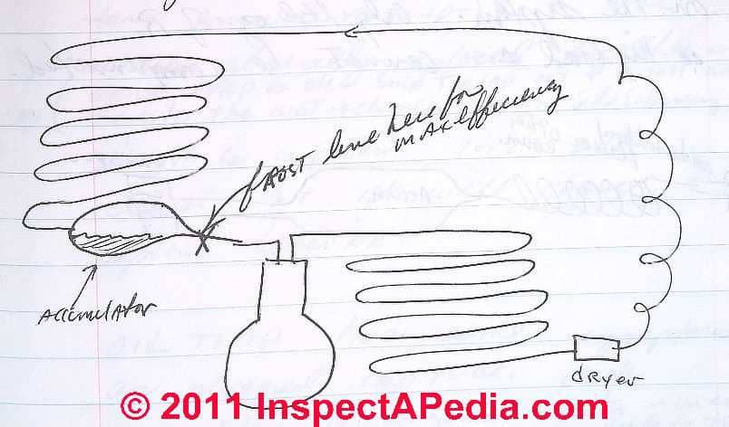
Our capillary tube refrigeration system schematic sketch (above left) shows the location of the capillary tube (red box at center top of the sketch) and a refrigerant accumulator (green arrow at lower left) at the end of the evaporator coil and ahead of the compressor motor.
In the capillary schematic we note that the appearance of the frost line just at the end of the refrigerant accumulator indicates the maximum - efficient refrigeration system design. The purple rectangle (lower right) is the position of the dryer canister at the outlet of the [red] condenser coil.
Air Conditioner or Refrigeration System Pressure Equalization, Capillary Tubes & the Function of the Accumulator
During the off cycle, the refrigerant continues to flow through the cap tube since there is no mechanical closing of this device. Therefore pressures on the high side and low side of the system will equalize.
An accumulator in the refrigeration system [green arrow points to the accumulator, the blue object at center left of our sketch above] will hold liquid refrigerant on the low side to keep liquid refrigerant out of the compressor bottom during the off cycle - thus avoiding damage to the compressor motor and its valves.
Preferably the accumulator is positioned horizontally in order to prevent a refrigerant oil-trap forming at the accumulator outlet opening.
...
What's the Difference Between a Refrigerant Capillary Tube or "Cap Tube" and a Refrigerant Expansion Valve or TEV / AEV?
 To the capillary tube the TEV adds a level of control - the TEV can open or shut in response to an attached bulb which actually monitors temperatures in the refrigerant tubing. Capillary tubes are found on residential refrigerators, dehumidifiers, and many window air conditioners. TEVs are found on larger air conditioners and central air conditioning systems where more control is needed.
In our TEV sketch (left) the small diameter tube at the top of the thermostatic expansion valve is connected to a temperature sensing bulb (not shown) that is located at the outlet end of the cooling or evaporating coil in the air handler.
The tubing at the left and right permit liquid refrigerant to flow into the valve from the compressor/condenser and, metered by the TEV, onwards into the evaporator coil.
The large nut on the bottom of this TEV covers an adjustment screw that can change the latent heat settings and thus the behavior of the valve once it is installed. (Normally you should leave the valve at its factory setting.)
As refrigerant liquid is metered into the entry point of the evaporator coil it is entering the low side of the air conditioning system. The change from high pressure to low pressure permits the refrigerant to evaporate, changing from a liquid to a gas
[The boiling point of R12 refrigerant is -21 degF, and the boiling point of R22 refrigerant is -41 degF. Newer refrigerants will have similar characteristics.]
It is this state change, from liquid to gas, occurring inside of the cooling coil (evaporator coil on the A/C system's low side) that absorbs latent heat, thus cooling the evaporator coil itself.
The job of the refrigerant metering device such as a capillary tube or a TEV is to provide a restriction in the refrigerant tubing system so that there will be a pressure difference maintained between the high side and low side of the system.
The air conditioning compressor, by pulling on the suction line or low pressure side of the closed refrigerant piping system is causing pressure to be low on that side. The same compressor is delivering high pressure liquid refrigerant to the high side of the system. The TEV is between these two pressure systems.
Latent heat, state change, high side and low side are defined in more detail
at SEER RATINGS & OTHER DEFINITIONS.
All cooling systems using refrigerants use some type of expansion valve, of varying complexity. Even a simple window air conditioner or a refrigerator make use of an expansion valve, in the form of a small-diameter capillary tube or "cap tube" which meters refrigerant into the cooling coil.)
Some Advantages & Disadvantages of Capillary Tubes for Refrigerant Metering
A capillary tube is a less costly refrigerant metering device than a refrigerant metering valve such as a TEV or AEV and it's patently simpler in operation.
A capillary tube design also allows the use of a smaller compressor motor since the motor does not face the same head pressure start-up load: pressure equalizes when the system is off, so there is no high head pressure at the compressor motor during start-up.
However where a capillary tube is metering refrigerant, the cooling load needs to be more or less constant - because of the precisely measured charge of refrigerant and the absence of a large refrigerant storage receiver canister, you don't have a large volume of refrigerant available for varied or increased release into the evaporator coil at times of high cooling load. In other words, variations in cooling load are not so easily compensated-for in a capillary tube refrigeration system design.
...
Diagnose & Repair Capillary Tube Refrigerant Metering Devices

Refrigerant overcharge on a capillary tube system: if the system has been overcharged you'll see higher pressure on the low-side of the system and an increased temperature in the system there.
The refrigeration system will run longer to reach the desired cooling temperature (refrigerator runs longer than it used-to, for example).
That's because we are seeing a higher compressor head pressure since we've put more refrigerant into a fixed volume space.
Our sketch illustrates a cap tube and accumulator ready to be connected into a refrigeration system: the left end of the tube will be soldered into the refrigerant line using a flare or swage connection and the right end of the accumulator has a connector intended for soldering to the compressor suction line.
See REFRIGERANT HIGH HEAD PRESSURE DIAGNOSIS
 Refrigerant undercharge on a capillary tube system: if the system is undercharged, you will see lower pressure on the low side but not enough refrigerant, so in this case too the system will run longer than normal.
Plugged capillary tube diagnosis:
if the cap tube becomes plugged with oil, debris, [or solder due to improper installation] the symptom will be that the low side will run in a deep vacuum. The compressor is unable to pull refrigerant through the capillary tube. And of course no cooling will be taking place at all.
An oil trap anywhere in a refrigeration system:
oil traps (refrigerant oil has blocked refrigerant piping or metering device) will produce the same symptom as a plugged capillary tube - that is, the system will run at a deep vacuum on the suction side or low side.
If you are diagnosing a capillary tube metered appliance, check the position of the accumulator. If it's become bent or moved out of horizontal, it's outlet end may be oil-trapped.
Visible capillary tube defects:
where the cap tube is visible such as in Carson Dunlop Associates' sketch (left), there are several defects that you can spot by simple visual inspection
- A crimped capillary tube
will not perform properly as the crimp obstructs or restricts refrigerant flow below the design point and also increases the chances of debris blockage - Loose capillary tubing
risks ultimately a refrigerant leak as vibration can wear through the tubing - Frost visible on the cap tube
is an abnormal condition (as there should be liquid refrigerant in the tube) and probably means low refrigerant and a leak or partial tube blockage - A punctured capillary tube
will bring the whole cooling system to its knees as you'll lose refrigerant and will lose cooling ability entirely.
More Help to Diagnosing Problems with Capillary Tubes for Refrigerant Metering
- REFRIGERANT LEAK DETECTION describes the effects of dirt and moisture on TEVs and capillary tubes.
A quick test for a moisture/ice jammed cap tube or TEV is to add some heat to see if the device will begin working again.
- Watch out: water or dirt in the system can cause serious and costly problems including clogging a capillary tube so that no refrigerant flows at all or clogging a thermostatic expansion valve causing irregular and improper metering of refrigerant.
...
Replacing a Capillary Tube on an Air Conditioner - Service Tips
Capillary tubing for refrigeration systems comes in a package that will include a chart that will help you specify the correct length to use.
Shown just below, we have prepared an example cap tube length table of sizes based on Gemline™ Capillary tubing. Some capillary tubing service packs such as GCPK will include multiple sizes or diameters of capillary tubing in standard 12-inch lengths.
Table of Refrigeration Equipment Capillary Tubing Sizes |
|
|---|---|
| Capillary Tube Size Denomination | Capillary Tube diameter in inches diameter[1] |
| GC-1 | 0.031 |
| GC-2 | 0.042 |
| GC-3 | 0.05 |
| GC-4 | 0.064 |
| GC-5 | 0.026 |
| GC-6 | 0.036 |
| GC-7 | 0.049 |
| GC-8 | 0.054 |
| GC-9 | 0.070 |
| GC-10 | 0.075 |
| GC-11 | 0.080 |
| GC-12 | 0.085 |
| [1] Gemline™ GCPK | |
Notes to the Table Above
Generally on small refrigeration systems that use a capillary tube to meter refrigerant into the cooling coil, the suction line is soldered to the capillary tube line.
This is done to increase vapor temperature going back to the compressor and to decrease refrigerant temperature going into the evaporator - both conditions that improve the operating efficiency of the refrigeration system.
But because of this co-soldering of the cap tube to the suction line, if the cap tube has to be replaced, generally both lines are replaced together.
OR, if the evaporator itself is OK, you can just snip off the capillary tube out of the system and install a new one in parallel, giving up the benefit of that side-by-side soldering of the new cap tube to the old suction line.
The length (and of course diameter) of the new capillary tube is important, but if you're off an inch or two on most appliances it's not going to be critical.
But a 12" change in capillary tube length will certainly change the behavior of the refrigeration system. If you make the cap tube too short the system run time will be increased beyond its normal or design point.
...
"Non-Adjustable" & Manually Adjustable Expansion Valves: How they are Set
Singer and other manufacturers point out that TEVs are adjusted at the factory before shipment.
The factory setting of a thermostatic expansion valve is printed on a label found on the head of the valve and for most installations the factory superheat settings should be left alone.
How & When to set "Non-Adjustable" Thermostatic Expansion Valves
Non-adjustable TEVs (such as Singer TEV models 226, 326, 426) can actually be adjusted before the valve is installed, by turning an adjustment screw through the valve outlet opening.
Once these valves have been installed, however, adjusting the valve would require removing it from the system, thus also requiring an evacuation and recharge of system refrigerant - not something to do casually.
How to Set Manually Adjustable Thermostatic Expansion Valves
Manually adjustable TEVs permit the device to be set to continuously maintain the proper refrigerant level entering the evaporator coil or cooling coil. Automatic expansion valves are discussed below.
- Adjustable TEVs include an adjusting stem
that can be turned with a screwdriver. Some valves may require that a covering cap be first removed to provide access to the adjusting screw or stem.
On Singer adjustable TEVs (other controls will be similar), - Turn the adjusting screw only one turn at time
to prevent over adjustment.
We make a tiny scratch on the valve bottom at the start end of the screw slot so that we can keep careful track of how far a screw has been turned. - To increase the superheat setting, turn the TEV valve stem clockwise.
When you turn the valve stem "in" or "clockwise" you are increasing pressure on the spring - the bellows will need more pressure to force the needle off of the seat, so the frost line will recede (less refrigerant is passing through) - and vice versa. - To decrease the superheat setting, turn the TEV valve stem counter-clockwise.
Normally the TEV is set for 7 to 12 degrees of superheat across the cooling coil (evaporator coil). - Allow the air conditioning or heat pump system to stabilize
for half an hour after each adjustment turn before trying to adjust the valve further.
Thank you to our readers for their generous comments
I would like to say that this kind of lesson is very helpful to carry out our job. - thanks, jaya. (May 29, 2012) j
...
...
Continue reading at REFRIGERANT PIPING INSTALLATION or select a topic from the closely-related articles below, or see the complete ARTICLE INDEX.
Or see CAPILLARY TUBE FAQs - questions & answers posted originally at the end of this article.
Or see these
Recommended Articles
- CAPILLARY TUBES
- CONTROLS & SWITCHES, A/C - HEAT PUMP
- EXPANSION VALVES, REFRIGERANT
- LOST COOLING CAPACITY air conditioning "running" but not enough cool air, or no cool air
- REVERSING VALVE on HEAT PUMPS
- REFRIGERANT PRESSURE READINGS & CHARTS - home
- THERMOSTATIC EXPANSION VALVE TEV INSTALL, DIAGNOSE, REPAIR
- THERMOSTATIC EXPANSION VALVES
Suggested citation for this web page
CAPILLARY TUBES for REFRIGERANT METERING at InspectApedia.com - online encyclopedia of building & environmental inspection, testing, diagnosis, repair, & problem prevention advice.
Or see this
INDEX to RELATED ARTICLES: ARTICLE INDEX to AIR CONDITIONING & HEAT PUMPS
Or use the SEARCH BOX found below to Ask a Question or Search InspectApedia
Ask a Question or Search InspectApedia
Try the search box just below, or if you prefer, post a question or comment in the Comments box below and we will respond promptly.
Search the InspectApedia website
Note: appearance of your Comment below may be delayed: if your comment contains an image, photograph, web link, or text that looks to the software as if it might be a web link, your posting will appear after it has been approved by a moderator. Apologies for the delay.
Only one image can be added per comment but you can post as many comments, and therefore images, as you like.
You will not receive a notification when a response to your question has been posted.
Please bookmark this page to make it easy for you to check back for our response.
IF above you see "Comment Form is loading comments..." then COMMENT BOX - countable.ca / bawkbox.com IS NOT WORKING.
In any case you are welcome to send an email directly to us at InspectApedia.com at editor@inspectApedia.com
We'll reply to you directly. Please help us help you by noting, in your email, the URL of the InspectApedia page where you wanted to comment.
Citations & References
In addition to any citations in the article above, a full list is available on request.
- [1] "Thermostatic Expansion Valve Installation Instructions", Singer Controls Division, Schiller Park IL, 197
- In addition to citations & references found in this article, see the research citations given at the end of the related articles found at our suggested
CONTINUE READING or RECOMMENDED ARTICLES.
- Carson, Dunlop & Associates Ltd., 120 Carlton Street Suite 407, Toronto ON M5A 4K2. Tel: (416) 964-9415 1-800-268-7070 Email: info@carsondunlop.com. Alan Carson is a past president of ASHI, the American Society of Home Inspectors.
Thanks to Alan Carson and Bob Dunlop, for permission for InspectAPedia to use text excerpts from The HOME REFERENCE BOOK - the Encyclopedia of Homes and to use illustrations from The ILLUSTRATED HOME .
Carson Dunlop Associates provides extensive home inspection education and report writing material. In gratitude we provide links to tsome Carson Dunlop Associates products and services.


