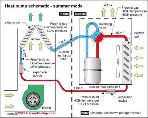
 Reversing Valves on Heat Pumps
Definition, Location, Function, Repair
- POST a QUESTION or COMMENT about heat pump reversing valves
Reversing valves:
This article gives a definition of a reversing valve used to switch a heat pump between cooling mode and heating mode.
We describe how a heat pump reversing valve works, how to find the reversing valve, and we include reversing valve troubleshooting advice and research articles. Page top sketch that includes a reversing valve is provided courtesy of Carson Dunlop Associates, a Toronto home inspection, education & report writing tool company [ carsondunlop.com ].
InspectAPedia tolerates no conflicts of interest. We have no relationship with advertisers, products, or services discussed at this website.
- Daniel Friedman, Publisher/Editor/Author - See WHO ARE WE?
Reversing Valves used on Heat Pumps
 Different or Additional Controls for a Heat Pump vs an Air Conditioner
At HEAT PUMPS we introduced the different controls required to allow heat pump equipment to function in both heating and cooling modes and we explained how a heat pump works to provide both heating and cooling for a building.
A heat pump is like an air conditioner, with a few control differences to allow the system to reverse the direction of heat movement between the indoor and outdoor areas.
When the heat pump is in cooling mode we are moving heat from inside of a building to the outdoors by blowing indoor air across a cooling coil, moving heat from the air into the coil and thus into the refrigerant in the coil.
Outside that heat is ultimately expelled into the outdoor air.
[Click to enlarge any image]
When a heat pump is in heating mode the pump is moving heat from outdoor air into the building interior by moving outdoor air across the same outdoor coil that is now in heating mode.
Depending on its efficiency, the outdoor compressor/condenser unit of a heat pump system can extract heat from outdoor air even down to temperatures below freezing.
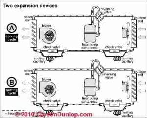
In an air conditioner-only system, the outdoor coil is used only to cool and condense high temperature high pressure refrigerant gas back to a liquid refrigerant, and the indoor coil is used only to expand the liquid refrigerant to a gas (through an expansion device such as a Thermostatic Expansion Valve (TEV) or a capillary tube (Cap Tube).
Because a heat pump has to be able to work in both directions, its indoor and outdoor coil have to be able to exchange roles. To accomplish this the heat pump will need two refrigerant metering and expansion devices, one at each coil. Only one of the expansion devices is operating at a given time - depending on whether the equipment is operating in a heating or in a cooling mode.
Illustrations of expansion devices and reversing valve operation on a heat pump were provided by Carson Dunlop Associates (found at page bottom, References Section), a Toronto home inspection, report writing & education company.
Reversing Valve and Defrost Cycle Operation Procedure for Heat Pumps
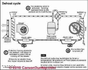
In addition to the two expansion devices, the system may make use of a reversing valve that changes the direction of flow of refrigerant gas and liquid in the system.
An additional set of controls for operation the refrigerant reversing valve and the operation of the defrost cycle for a heat pump are illustrated at left. During a defrost cycle
- The reversing valve changes direction of the refrigerant flow to send warmed refrigerant "freon" to the outdoor coil in order to melt ice that may have formed there.
- During the defrost cycle the outdoor fan stops - we want to stop moving outdoor air across the outdoor coil in order to allow the warm refrigerant to warm the coil.
- If the system includes electric heating elements, one stage of the electric
BACKUP HEAT for HEAT PUMPS may be activated in the blower compartment to warm air coming off of the blower.
If the heat pump system does not include electric backup heaters, the indoor air handler blower will stop during the defrost cycle so that we don't' blow wrong-temperature air into the occupied space.
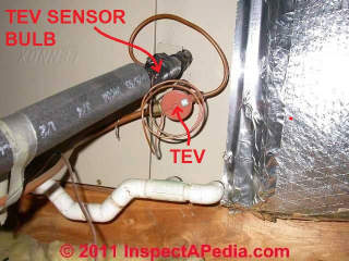
Below: a photograph of a thermostatic expansion valve or TEV used on a heat pump system.
The thermostatic expansion valve or TEV (or TXV) shown in the photo is used on a heat pump system so it includes extra tubing so that as we will explain here, with the heat pump's reversing valve the TEV can permit the refrigerant to reverse its flow of direction when changing from cooling mode (move indoor heat to outdoors) to heating mode (collect and move outdoor heat to indoors).
Simple Tests Diagnose Heat Pump Reversing Valve Problems
To detect a defective reversing valve the HVAC service technician will simply measure the temperature on each of four lines going to and from the reversing valve.
She will observe the following if the reversing valve and heat pump system is working normally:
In Heating Mode
- The discharge gas line (the hot line) will go through the reversing valve port that leads to the indoor coil as we want to send heat into the indoor (heating) coil in the air handler
- The suction gas line (the cool or cold refrigerant line) will go be coming from the outdoor coil
In Cooling Mode
- The discharge gas line (the hot refrigerant line) will go through the reversing valve port that leads to the outdoor coil since we want to send heat outdoors
- The suction gas line (the cool or cold refrigerant line) will be coming from the indoor coil since we
Note: the reversing valve might be actuated to switch between heating and cooling mode in two ways:
- A room thermostat includes a switch from HEAT to COOL, typically using a wire connected to the "O" (orange wire) terminal that operates the reversing valve
- A control circuit board in the heat pump may operate the reverse valve in order to provide a defrost cycle for the system
Where is the Physical Reversing Valve Located?
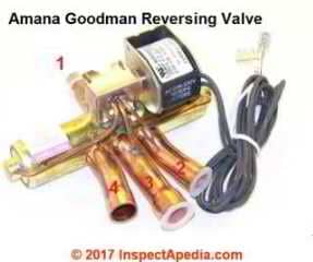 The reversing valve will normally be found built into the heat pump compressor/condenser unit and soldered to refrigerant pipes or lines like those shown in this photograph adapted from a Goodman / Amana reversing valve
We added numbers to point out the four refrigerant connection ports on the valve. You can see the actuator coil assembly on the right side of the valve along with its connecting wires to connect the valve to the heat pump's control board.
Question: repair a capillary tube with epoxy?
(May 13, 2014) Ron said:
Can leaking capillary tubing entering solenoid body of the reversing valve in a R-22 system be repaired with epoxy.
Reply:
Ron,
Interesting question. I'm doubtful that a leaky cap tube can be reliably repaired, in part because I figure that you'll get epoxy in the small orifice of the tube interior and foul up its metering rate.
It's worth a try anyway as if you ruin it you needed a new one anyway. Clean the surface, dry it, and try a patch.
Reversing Valve Specifications, Sources, Research
- ACHR News, "Don't let that reversing valve outsmart you" [Web & magazine article], the NEWS, retrieved 2017/05/30, original source: http://www.achrnews.com/articles/82944-don-t-let-that-reversing-valve-outsmart-you
- Bertsch, Stefan S., and Eckhard A. Groll. "Two-stage air-source heat pump for residential heating and cooling applications in northern US climates." International Journal of Refrigeration 31, no. 7 (2008): 1282-1292.
- Damasceno, G. D. S., W. N. T. Lee, S. P. Rooke, and V. W. Goldschmidt. "Performance of heat pump reversing valves and comparison through characterizing parameters." ASHRAE transactions 94, no. 3112 (1988): 304-317.
- Goodman Air Conditioning and Heating, Heat Pump Non-Programmable Digital Thermostat Manual [PDF] allows control of 1 or two heat and one cooling system. Goodman Consumer Affairs, 7401 Security Way, Houston TX 77040 USA, Tel: 877-254-4729, This manual illustrates the thermostat connections that in turn operate the heat pump's reversing valve.
- Krishnan, R. R. "Evaluating reversing valve performance in heat pump systems." ASHRAE Trans.;(United States) 92, no. CONF-8606125- (1986)
Abstract:
A method to determine the various effects on the performance of a heat pump system due to a reversing valve is described. The method can be used effectively to compare the effects on a given system by different valves and thus can be used by end-product manufacturers in selecting sizes and sources of supply.
The concept used in this analysis considers the compressor and the reversing valve as a combined unit in a heat pump system.
Using a calorimeter setup, the changes in performance of this combined unit of components can be studied at various inlet and outlet conditions, in much the same manner as a compressor's performance characteristics are analyzed. In conclusion, it is shown how the reversing valve has less of an effect on system performance in comparison to its effect on the compressor by itself.
One valve that was tested showed a degradation of about 5% in a system, whereas it dropped the performance of the compressor alone by about 8%. The empirical method proposed herein can be used effectively in valve comparisons without actually having to resort to system testing. - "Reversing Valve", Retrieved 2017/05/30, original source: https://en.wikipedia.org/wiki/Reversing_valveWikipedia provided background information about some topics discussed at this website provided this citation is also found in the same article along with a " retrieved on" date. Because Wikipedia and other website entries can be amended in real time, we cite the retrieval date of such citations and we do not assert that the information found there is always authoritative.
...
Continue reading at THERMOSTATIC EXPANSION VALVES or select a topic from the closely-related articles below, or see the complete ARTICLE INDEX.
CONTROLS & SWITCHES, A/C - HEAT PUMP
Or see these
Articles on Heat Pumps
Suggested citation for this web page
REVERSING VALVE on HEAT PUMPS at InspectApedia.com - online encyclopedia of building & environmental inspection, testing, diagnosis, repair, & problem prevention advice.
Or see this
INDEX to RELATED ARTICLES: ARTICLE INDEX to AIR CONDITIONING & HEAT PUMPS
Or use the SEARCH BOX found below to Ask a Question or Search InspectApedia
Ask a Question or Search InspectApedia
Try the search box just below, or if you prefer, post a question or comment in the Comments box below and we will respond promptly.
Search the InspectApedia website
Note: appearance of your Comment below may be delayed: if your comment contains an image, photograph, web link, or text that looks to the software as if it might be a web link, your posting will appear after it has been approved by a moderator. Apologies for the delay.
Only one image can be added per comment but you can post as many comments, and therefore images, as you like.
You will not receive a notification when a response to your question has been posted.
Please bookmark this page to make it easy for you to check back for our response.
IF above you see "Comment Form is loading comments..." then COMMENT BOX - countable.ca / bawkbox.com IS NOT WORKING.
In any case you are welcome to send an email directly to us at InspectApedia.com at editor@inspectApedia.com
We'll reply to you directly. Please help us help you by noting, in your email, the URL of the InspectApedia page where you wanted to comment.
Citations & References
In addition to any citations in the article above, a full list is available on request.
- Huang, Dong, Quanxu Li, and Xiuling Yuan. "Comparison between hot-gas bypass defrosting and reverse-cycle defrosting methods on an air-to-water heat pump." Applied Energy 86, no. 9 (2009): 1697-1703.
- Huang, Dong, Xiuling Yuan, and Xingqun Zhang. "Effects of fan-starting methods on the reverse-cycle defrost performance of an air-to-water heat pump." International Journal of Refrigeration 27, no. 8 (2004): 869-875.
- Omer, Abdeen Mustafa. "Ground-source heat pumps systems and applications." Renewable and sustainable energy reviews 12, no. 2 (2008): 344-371.
- Self, Stuart J., Bale V. Reddy, and Marc A. Rosen. "Geothermal heat pump systems: Status review and comparison with other heating options." Applied Energy 101 (2013): 341-348.
- Zhiyi, Wang, Wang Xinmin, and Dong Zhiming. "Defrost improvement by heat pump refrigerant charge compensating." Applied Energy 85, no. 11 (2008): 1050-1059.
- Our recommended books about building & mechanical systems design, inspection, problem diagnosis, and repair, and about indoor environment and IAQ testing, diagnosis, and cleanup are at the InspectAPedia Bookstore. Also see our Book Reviews - InspectAPedia.
- In addition to citations & references found in this article, see the research citations given at the end of the related articles found at our suggested
CONTINUE READING or RECOMMENDED ARTICLES.
- Carson, Dunlop & Associates Ltd., 120 Carlton Street Suite 407, Toronto ON M5A 4K2. Tel: (416) 964-9415 1-800-268-7070 Email: info@carsondunlop.com. Alan Carson is a past president of ASHI, the American Society of Home Inspectors.
Thanks to Alan Carson and Bob Dunlop, for permission for InspectAPedia to use text excerpts from The HOME REFERENCE BOOK - the Encyclopedia of Homes and to use illustrations from The ILLUSTRATED HOME .
Carson Dunlop Associates provides extensive home inspection education and report writing material. In gratitude we provide links to tsome Carson Dunlop Associates products and services.


