 Structural Wood Timber or Beam Damage Assessment
How experts assess the structural integrity of wood framing or wood timbers in-situ using micro-drilling

- POST a QUESTION or COMMENT about methods used in testing structural wood members for damage or decay & the role of micro-drilling tests for in-situ evaluation of structural wood beams, timbers, or other framing members in buildings..
Test methods for determining the soundness of wood structural members:
This article series surveys methods used to test & evaluate the structural integrity of wood-framed buildings where focus is on the condition of structural wood posts, beams and other framing members.
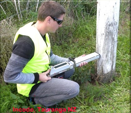
We discuss the problems surrounding hidden rot or decay, the presence or absence of moisture or other instrument-detectable clues, and the problem of subjective decisions to replace or not-replace suspect wood structural members. Page top image of micro-drilling, USDA FPL [20].
This article compares using using micro-drilling with other methods to screen both standing trees and wood structural elements for hidden damage.
The original authors, Probett et als., propose a technique to provide objective pass-fail data on the condition of in-situ but suspect structural wood using micro drilling to examine wood density. This service uses timber resistance drill technology to profile variations in timber density associated with timber decay.
InspectAPedia tolerates no conflicts of interest. We have no relationship with advertisers, products, or services discussed at this website.
- Daniel Friedman, Publisher/Editor/Author - See WHO ARE WE?
Survey & Evaluation of Methods Used for Structural Wood Timber or Beam Assessment
 Paul Probett, Clinton Craig, Blake Probett, Incodo Forensic Building Specialists [1]
This article series on methods for assessing structural wood rot & damage is adapted & expanded from the author's "An Introduction to Micro-Drilling Technology for N. Z. Structural Timber Assessment" and is used with permission. We [DF] have added comments, some illustrations, and additional article citations.
At the references section we include a link to the original article as well as contact information for the authors and Incodo Ltd., a Tauranga, New Zealand forensic engineering firm. The original authors' article without the expanded discussion added here can be seen at An Introduction to Micro-Drilling Technology for N. Z. Structural Timber Assessment. [PDF]
Additional comments, illustrations, and technical citations addressing wood structure testing technologies have been added. We and the original authors invite and will reply to reader questions and comments using the comments box found at the end of this article. Initial technical review completed 8/6/201
[Click to enlarge any image or illustration]
Article contents
- WOOD STRUCTURE ASSESSMENT - History of Methods Used for Standing Trees & Wood Timber Assessment. Table of features, operating procedures, costs, effectiveness of various methods for standing trees or for wood structural member assessment.
The work is done on site and the results are instant. This technology is objective and evidential in nature and provides assessment as to whether wood is significantly decayed, suspect or suitable for retention. we describe the relationship between construction details and the occurrence of structural rot in timber frame buildings.
CURRENT IN-SITU WOOD BEAM ASSESSMENT METHODS - In-situ Wood Beam, Timber, or other Wood Framing Member Structural Condition Assessment Methods. In situ Timber Assessment Compared with Other Current Bases for Wood Structural Member Assessment.- TABLE of TREE DECAY DETECTION EQUIPMENT
- WOOD BEAM VISUAL INSPECTION - Visual Inspection Methods for Wood Structural Member Assessment
- WOOD BEAM MICROBIOLOGICAL ASSESSMENT - Microbiologist / Mycologist Methods for Wood Structural Member Assessment
- WOOD BEAM FRACTOMETER TESTING - Fractometer Methods for Wood Structural Member Assessment
- WOOD BEAM PILODYN TESTING - Pilodyn Methods for Wood Structural Member Assessment
- WOOD BEAM MICRO-DRILLING ASSESSMENT - Micro-Drilling: Resistance drill Methods for Wood Structural Member Assessment. Incodo Testing Program of Micro-Drilling for Wood Assessment
- WOOD BEAM MICRO-DRILLING PROCEDURES - details of how micro drilling is used to assess wood structural member condition
- WOOD BEAM MICRO-DRILLING EFFECTIVENESS - Incodo study of microdrilling for wood structure assessment
- WOOD BEAM ROT ASSESS: MOISTURE METERS - are moisture meters useful for rot detection in structural members?
- WOOD BEAM ROT ASSESS: THERMOGRAPHY - are infra red IR scanners and thermography equipment effective in detecting structural rot in wood beams?
Introduction: A Brief History of Methods Used for Standing Trees & Wood Timber Assessment
A variety of tools and methods for assessing the condition of standing trees as well as the structural integrity of in-use wood timbers & beams has been in use for decades.
Several methods for obtaining drill samples or core samples from standing trees have long been in use by agencies such as the U.S. Forest Service and agencies in other parts of the world as part of evaluating the condition of standing timber and forests. [16]
In addition a variety of other methods such as ultrasound, stress waves, electrical resistance testing, mechanical coring or boring, visual inspection, and even a simple plastic hammer have been used to evaluate possible decay or insect damage in both trees and other exposed, accessible wood structural elements.
Methods used initially to evaluate standing timbers were quite naturally expanded to permit assessment of the structural integrity and condition of key wood structural members that are completely exposed and thus readily accessible, such as timber-constructed bridges, bridge pilings, telephone poles, railroad ties, as well as engineered lumber such as block-laminated timbers. [2][3][4][5][6][7][8][9][10] and [19][20][21][22][23]
 The presence of those tools and methods for testing exposed timbers suggested possible applications in the evaluation of buildings and other structures in which their structural wood members may be partly or even completely hidden by finish materials.
More recently, Bohumil Kasal & Thomas Tannert have led research on the design of microdrilling methods and on the reliability of such tests in predicting the actual bending or breaking strength of structural wood members.
It was Kasal who developed recent technology of taking micro specimens of wood that in turn might be used to obtain direct measurements of the modulus of elasticity and strength of wood (in the area tested).
A direct measurement of the tension properties of wood along the wood fibers permits bending strength evaluation - important because bending strength is a key property in evaluating the structural integrity of a wood beam. Kasal's significant observation was that
...
tensile strength has been related to bending strength and is considered to be approximately equal. Tensil properties have a poor correlation with compression properties therefore tensile strength can not be estimated using information attained with the core drilling technique.
Specimens can however be extracted to evaluate the tensile properties of in situ members with the technique [described by Kasal]. [5]
Here, in expansion of an original article by Probett et als [1] , here we discuss the range of structural wood beam or timber assessment methods where wood beams, timbers, or other structural members are used in buildings and where there is known or suspected risk of structural damage from leaks, decay by wood rotting fungi, or damage by wood destroying insects.
Because Probett et als propose and discuss the applicability of micro-drilling test methods for assessing wood structural members in-situ with or without having to perform more extensive demolition to actually expose the members, special attention is given to this method of structural assessment of wood, including Probett et als' test protocol and progress in evaluating the efficacy of this method.
Watch out: Important additional research on the efficacy of microdrilling has been conducted in the U.S. by the USDA Forest Products Laboratories by Brian K. Brashaw et als using the IML RESI F300-S.
That 2005 study provides important independent experience and assessment of the micro-drilling approach to structural wood testing.
As you will read in our inserted opinions and warning remarks in the article below, wood testing equipment should not be used by itself to form conclusions about a structure. Excerpting from the Brashaw micro-drilling study conclusions:
It is crucial to use this or any nondestructive testing tool or device as part of a comprehensive condition assessment. Such an assessment should incorporate an in-depth visual inspection, knowledge of prior use of the structure, and a working knowledge of fundamental engineering properties of structural wood products.
This technique, when used in concert with visual and ultrasound techniques, would provide a very accurate description of the condition of timbers. [20]
Why perform in-situ timber or wood structural member assessment?
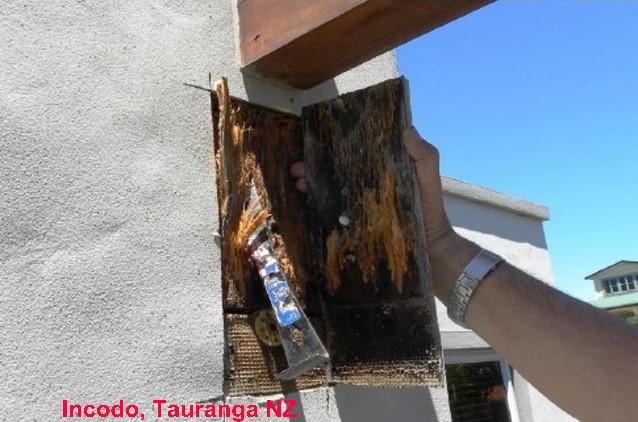
- The timber in many New Zealand (NZ) buildings and structures is either untreated, or exposed to conditions beyond that of deigned treatment levels. Structural damage as a result of leaky homes or premature decay or just aging and attack by bacteria, wood-rotting fungi, and insects is widespread.
- Traditional methods used to determine soundness of timber have been either invasive / destructive to envelopes and interior surfaces or based largely on visual assessments.
In situ Timber Assessment Compared with Other Current Bases for Wood Structural Member Assessment
- Current basis of most decisions to retain or replace is ‘visual and chisel’ with limited microbiological backup often from “money shot” areas.
- Replacement decisions are frequently based on a conservative approach i.e. everything within 1.0m from last decay point to be replaced – emphasis is on all degrees of decay replaced. In the absence of better information the approach is considered to have some merit
- The results tend to be subjective, rather than having been based on objective and evidential data.
These conditions result in two significant error risks:
- Failing to repair or replace structural damage that thus risks a costly or injurious building collapse
- Repairing or replacing materials that actually are serviceable, resulting in significant and unnecessary costs
In situ Timber Assessment Impact on Government Departments and Local Authorities
- Possibility that more framing than strictly necessary is being replaced – impacting on FAP contributions, and Councils in particular when FAP* not pursued.
* FAP in New Zealand refers to a weatherization Financial Assistance Package provided through the Building & Housing agency of the Ministry of Business, Innovation & Employment. More information about FAP can be found at http://www.dbh.govt.nz/fap - Evidence provided by claimant in disputes tends to be opinion based and hard to challenge.
- Degree of remediation design is determined by early report snapshot findings and assumptions. This tends to lock works into a specific approach – with little opportunity for reclads to be lessened to targeted repairs or partial reclads.*
- The current absence of a widely available cost effective non-destructive in situ test methodology for timber structural element assessment has limited options for remediation.
* Note Incodo is the original authors' forensic consulting firm. Incodo’s niche is providing building forensic assistance and inspection technology to government departments, consultants and others. Incodo does not undertake remediation project management, remedial design, prepurchase or similar work.
Similarly
InspectAPedia is an independent publisher of building, environmental, and forensic inspection, diagnosis, and repair information provided free to the public - we have no business nor financial connection with any manufacturer or service provider discussed at our website.
Current In-situ Wood Beam, Timber, or other Wood Framing Member Structural Condition Assessment Methods
Current choices for assessing the structural integrity of wood timbers, beams, or other framing members include the following:
- WOOD BEAM VISUAL INSPECTION
- WOOD BEAM MICROBIOLOGICAL ASSESSMENT
- WOOD BEAM FRACTOMETER TESTING
- WOOD BEAM PILODYN TESTING
- WOOD BEAM MICRO-DRILLING ASSESSMENT
- WOOD BEAM ROT ASSESS: MOISTURE METERS
- WOOD BEAM ROT ASSESS: THERMOGRAPHY
Each of these approaches to detecting wood beam rot and assessing its extent and its impact on the condition and serviceability of the wood member being examined is discussed and compared in the article segments listed above.
Visual Inspection Methods for Wood Structural Member Assessment

Expert eye (“visual n chisel”).
We contend that this approach is subjective and has issues regarding cost, independence between the assessor and the remediator, liberal vs. conservative "safe" approaches to deciding what replacement is needed, and that in some cases visual inspections lack adequate evidential basis for decisions.
Nevertheless, 99% of building assessments use this approach.
The scope of visual-based wood structure inspections focuses on the visible surface of materials.
Additional properties of the visual & chisel approach to building structural damage assessment:
- Highly subjective – based on experience and opinion – some “brashness” /chisel testing of suspect areas. Often supported by microbiological testing which adds to net cost
- Often linked with conservative approach
to extent of removal - the expert plays it safe, avoiding personal liability by spending more of the client (or government's) money - Relatively expensive and report quality ( if prepared) varies
- Some inspection reports are not objective
scientific or to an evidential level. - Other inspection reports rely only on lab tests
but offer no or insufficient actual onsite inspection and no or insufficient interpretation of the lab test report results.
Watch out: we [DF] receive frequent consumer complaints from people who hired an "expert" to inspect their home for hidden damage only to find that the expert did little other than collect a test sample, without any actual building inspection.
The test sample is "tossed over the wall" to a forensic test laboratory who in turn issue a report based solely on the sample contents. The "expert" defers to the lab report and offers no useful interpretation of the test report.
The lab cannot adequately interpret the significance of the test sample finding because no one there has examined the structure concerned nor interviewed its occupants. - May miss hidden decay if the expert is not adequately trained & experienced
- High likelihood of missing timber degraded to non- compliant levels particularly between double studs and joists or at similar potential problem spots that are not visually accessible and for which there is not yet any external building evidence such as sagging, cracking, movement. The risk of this error is increased if the inspector does not attend to secondary clues such as stains, building leak history, construction details that are prone to developing leaks, rot, insect damage.
- Some defects or the extent of building damage cannot be effectively assessed until cladding or linings have been removed
Watch out: a building inspection to assess the risk of hidden damage to its wood structure, when performed by an experienced professional will consider the entire structure based on a thorough outside as well as inside inspection.
The inspector recognizes building methods, materials, or site conditions that tend to cause moisture, leaks, or rot problems as well as recognizing visually obvious examples of such damage.
Where the site conditions and history justify further, more invasive inspection (such as making test cuts to explore the most-suspect areas) the inspector is expected to so indicate. Such an inspection balances the risk of hidden damage against the costs of unnecessary or unjustified destructive or invasive inspection methods.
See TIMBER FRAMING, ROT and
also MOISTURE CONTROL in BUILDINGS - DF
Note: I [DF] agree that the actual visual inspection of building conditions, lacking "X-ray vision", is limited to external or surface observations. However a skilled and experienced observer can predict areas where hidden damage is most likely at a particular building by considering building and site history, construction materials, construction methods, and by familiarity with construction details that tend to lead to building leaks, moisture problems, rot, damage.
Therefore I have addia.com/home_inspection/Building_Inspection_Techniques.php">ADVANCED INSPECTION METHODS "Developing your X-Ray Vision" - DF
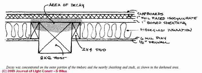
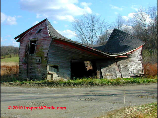
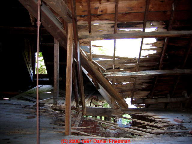
This sketch, courtesy of Steven Bliss & The Journal of Light Construction, illustrates the problem of structural decay that may be completely hidden as well as "dry" at the time of a building inspection.
At TIMBER FRAMING, ROT we discuss this problem in detail, and at
ADVANCED INSPECTION METHODS we emphasize the importance of thorough, experienced, attentive inspection to not just evidence of damage, but evidence of construction materials and methods that tend to cause damage - the risk points at a building. - DF
More-expert inspectors make limited use of instruments such as moisture meters, infra-red scanners & thermography, and more significantly, by familiarity with construction methods and materials, building science, and building failures, an expert inspector can focus attention on areas where hidden damage is most likely to occur.
But as we and the USDA FPL warned at the start of this article, an expert who approaches building assessment most effectively does not allow the use of an instrument to substitute for a thorough visual inspection and site history recording.
Microbiologist / Mycologist Methods for Wood Structural Member Assessment
Expert, samples, time, cost. Often additional to visual assessment
Scope = Microscopic to sample size (minor usage in deciding actual replacement, adds genuine weight to reports). Not in situ assessment
Note: in our opinion, microbiologists and aerobiologists can provide a useful supporting role in assessing building conditions (mold or other IAQ hazards) including providing additional screening for evidence of hidden but active wood destroying fungi.
Few microbiologists nor mycologists have the requisite familiarity with building science and construction failures to serve as a primary building screener for hidden damage.
But those sciences can add important depth of understanding to field observations by others. For example, a mycologist can explain that if we see "mushrooms" growing out of wood framing members, there is almost certainly substantial hidden rot damage that merits further invasive inspection.
Similarly, the identification of some mold genera/species by spore trap or dust sampling can yield important insights into building conditions and the risk of hidden damage.
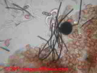
For example we have found high levels of Meruliporia incrassata. spores in building environmental samples at levels indicating a nearby infection of this wood destroying fungus. But unless the work is conducted by someone who is also expert in building science and who is also familiar with construction methods and construction inspection methods, such assessments are likely to be unreliable.
See Meruliporia Mold Photographs for details. Photo, above left of Meruliporia incrassata and other fungal materials - Daniel Friedman, InspectAPedia lab.
Watch out: In our view, building "testing" by collecting surface, air, or dust samples for lab analysis, while they can considerably expand the scope of a building assessment beyond "microscopic sample size", are of questionable accuracy unless there is accompanying expert visual inspection and history taking.. - DF
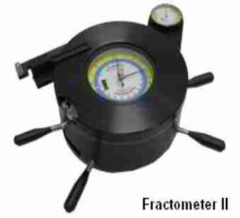
Fractometer Methods for Wood Structural Member Assessment
5mm cores required – compression, bending and torsional tests.
Scope = Specific samples only, but comprehensive. Not in situ assessment.
With the use of the increment borer one can take a core sample out of a wooden structure with a diameter of 5 mm. This core sample is then used for assessing with the Fractometer Print.
A Fractometer Print puts bending load on the core sample that was taken from a wooden structure until it breaks.
The bending break moment and the breaking angle can be determined as can compression strength and other measures.
The Fractometer has been described in IML's instruction manual where bending strength, fiber direction, and related concepts are detailed. - IML is Instrumenta Mechanik Labor System, Wiesloch, Germany. [15] .
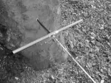
Pilodyn Methods for Wood Structural Member Assessment
Instant, cost effective.
Scope = 40mm (density loss measurement). Generally not used on buildings. Largely utility poles only for shell decay testing.
According to Pilodyn and corvib.com, the Pilodyn is suitable for trees, railway ties and utility poles. According to Ferret (AU), the Pilodyn is also suitable for testing the stability of wooden structures on playgrounds, detection of soft rot.
Pilodyn illustrations from Corvib.com. [17]
- Pilodyn Advantages / Disadvantages:
- 40 mm penetration maximum
- Spring loaded penetrometer
- Sound timber equates to only 15-25 mm penetration
- Analogue scale
- Cost about $1000 - 2000. NZ per assessment
- Disposables cheap – pins only
- Hidden decay difficult to identify
- Extremely robust
- The Pilodyn wood tester (Hylec Controls) is described by and currently available from InTech/NDE U.S. Tel: 905-716-5604 / 800-297-3208, or Email: bnadeau@intechnde.com, and is also available from Hylec Controls via Ferret.com in Australia. - DF [17][18][19]
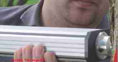
Micro-Drilling: Resistance drill Methods for Wood Structural Member Assessment

- Capital and start-up cost high, evidential, and instant.
- Scope = Full depth of sample, instant strength loss measurement
- Microdrill equipment is provided by
- Siebert Technology, England: SIBTEC Digital microProbe
- IML, Germany: IML Resistograph
- Details are provided in this article just below.
Image of micro-drilling, USDA FPL [20] .
Additional Wood Decay or Damage Testing Instruments / Methods
Bob Monk, USDA Forest Service, discussed the use of various types of equipment capable of detecting decay in standing trees - the epitome of in-situ testing. Monk described and tested an extensive list of tools and methods for assessing the condition of trees, possibly also used for structural wood member evaluation.
Monk's USDA article expands upon the types of options and test instrument applications discussed here.
The following table of tree decay detection equipment is adapted from Mr. Monk's USDA article [16] - DF
Table of Tree Decay Detection Equipment |
|||
|---|---|---|---|
| Equipment Type & Basic Properties | Wood Test Tool Name | Wood Test Tool Cost $USD | Manufacturer / Source |
Ultrasonic wood decay detection A sound wave is transmitted through the wood to a receiver; decayed wood slows the stress-wave signal. Stress waves vary by wood species. This approach permits multiple readings (for free-standing readily-accessible timbers or of course, for trees) thus permitting a 2-D map of the extent and location of wood decay. Limited to 1m of thickness; errors arise if sensors not properly placed. Early decay hard to spot. |
Arborsonic Decay Detector | $3,000. | Fujikura Europe, England |
| James "V" Meter | $2,650. | James Instruments, Chicago, IL | |
| Sylvatest | n/a | Sandes SA, Switzerland | |
| FAKOPP Ultrasonic Timer | $2,580. | FAKOPP Ent., Hungary | |
| Picus Sonic Tomograph (12 sensors + software) |
$18,000. | Fujikura Europe, England | |
Stress Wave Timer wood decay detection Similar to Ultrasonic method above, using a lower frequency signal generated by a tap-hammer. Can handle larger diameter trees than ultrasonic. Similar limitations + wood decay type impacts detection: brown-rot fungi damage easier to detect than white-rot fungi damage. May not detect some types of decay. |
Metriguard Model 239A | $5,375. | Metriguard, Pullman, WA |
| FAKOPP Microsecond Timer | $1,970. | FAKOPP Ent., Hungary | |
| FAKOPP 2D Microsecond Timer 6,8,16-channel versions | $4,820 - $11,390 | FAKOPP Ent., Hungary | |
| IML Impulse Hammer | $2,000. | IML, Germany | |
Microdrill wood decay detection A small 2-3mm probe-drill up to 1m in length penetrates the wood using a constant, measured force. The force required for the drill to penetrate is measured and graphed. Information is limited to the area immediately surrounding the drill probe. Cannot detect early stages of wood decay. The drill opening may spread decay or invite new decay. Units with a flexible probe can present deflection errors. Longer probes add significant cost. |
SIBTEC Digital microProbe basic kit + Field Printer |
$7,000. + $1,600 |
Sibert Technology, England |
| IML Resistograph F-series (300 - 500 mm) + w/electronic unit |
$3,800 - $4,600. + $2,000 |
IML, Germany Note: USDA FPL Study [20] found 25 -100% - Sound Wood |
|
| IML Resistograph - 2012 model | Comment: Resitogrpah's new drill (the PD) is substantially different from the one used as the basis of the 2005 article referred to. That model was (apparently) based on an attachment fitted to a battery drill and drill penetration speed and rotation speed were linked mechanically. The new drill has independent computer control for penetration depth rate and rotational speed is set – not subject to how hard the operator squeezes the trigger. The embedded firmware is also programmable to detect cavities and other anomalies such as splits and checks AND ignore defects that the operator adjusts settings for. We have also developed a report template ( word with xl spreadsheet embedded ) and are using Dell tablets with WIN 7 so that results are wirelessly sent from the drill and the report is prepared as investigation proceeds. Either we preload elevations for onsite mark-up of test areas or take a photo with the tablet and mark-up on the photo we embed in the report. - P.P. |
||
| Other Micro-drilling resistance tool suppliers | Tree Solutions, Seattle, Washington SIBTEC Scientific, DmP (Digital microProbe) (United Kingdom) Resistograph™, Frank Rinn, Heidelberg, Germany. |
||
Electrical Resistance wood decay detection A 2.38mm dia. drilled hole receives an 8" - 12" long sensing probe. Decaying wood cells release metal ions that change wood resistivity. Detects decay immediately adjacent to the test hole. This method can detect early stages of decay not detected by micro-drilling. Variations in wood moisture (season for living trees, building conditions for timbers) affect individual readings - possibly compensated for by taking comparative readings at other locations in the same timber. Borings may invite or spread decay. Other less invasive wood resistivity measurement methods are available (Larsson et als). |
Shigometer | $1,700. | Osmose Wood Preserving, Buffalo, NY |
| Vitalometer | France | ||
Mechanical wood decay detection A very sharp core cutting tool removes a wood sample then measured on a stiffness/breaking-strength scale. The result is compared with a data for wood species. (Not all species provided) Data only pertains to area immediately adjacent to the test opening. Multiple borings may be needed. Studies found this tool provided a sensitive method for both white & brown rot fungal damage. Borings may invite or spread decay. |
Fractometer I Fractometer II Fractometer Electric |
$1,000. $2,000. $4,000. |
IML Germany |
Mechanical wood decay detection A long thin probe is inserted into a pre-drilled hole in the wood / tree. The insertion process uses a self-firing spring-loaded punch to progress into the opening. The number of "punches" measures wood density and condition. Properly-sized drill hole is critical for accurate measurement. Data only pertains to area immediately adjacent to the test opening. Multiple borings may be needed. Borings may invite or spread decay. |
Portable Compression Meter | n/a | N/A |
Visual wood decay detection Can include visual examination of wood taken by a core sampler. |
Increment Borer | $200. - $500. | Several |
Manual wood decay detection Portable drill and long thin 9mm bit used by an expert can quickly detect decay by noting resistance to drilling, discoloration of wood in the drill bit flutes, even sense of smell. Multiple borings may be needed. Borings may invite or spread decay. |
Plastic Mallet Portable drill & common bit |
$ 10. $50. |
Various |
| Wood or Tree Test Instrument Manufacturer Contacts | |||
| Fujikura Europe | http://www.fujikura.co.uk/ | ||
| James Instruments | http://www.ndtjames.com/ultrasonic.html | ||
| Fakopp Ent | http://www.fakopp.com/main.htm | ||
| Sylvatest | http://www.cbs-cbt.com/TECH/index_s_en.html | ||
| Metriguard | http://www.metriguard.com/metprod.htm | ||
| IML | http://www.imlusa.com/index.php | ||
| Sibert Technology | http://www.sibtec.com/digitalmicroprobe.html | ||
| Osmose Wood Preserving | http://www.osmose.com/utilities/products/accessories/ | ||
Notes to the table above
Adapted from Evaluation of Decay Detection Equipment in Standing Trees, Bob Monk, USDA Forest Service [16]
Mr. Monk's comments include the following qualifications about the equipment in this list:
More sophisticated devices such as X-ray, gamma ray tomography, magnetic resonance imaging, and thermal imaging are limited in use because of cost and practicality of field use. Some of these latter devices may have more practicality with evaluation of logs rather than standing trees.
There is a large amount of information available about individual pieces or types of equipment.
There is also some information comparing some of the devices. Some information is in formal reports and some is more anecdotal, some is by the manufacturers of the equipment (need to be careful not to put too much weight on their claims). S
o far no report has been found that compares all of the equipment. Much of the work has been done in Europe (England and Germany mainly) and that is where much of the equipment is manufactured.
Moisture Meters Useful in Spotting Areas of Extra Risk of Structural Rot Damage
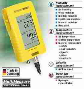
Our preferred moisture meter is a Trotec T2000 http://www.trotec.de/en/product-catalog/measuring-instruments/multi-function/t2000/.
This tool accepts a wide range of input sensors including 16+ variations on pin type electrodes for measuring moisture in wood. Quoting from the manufacturer:
Multifunctional measuring instruments with digital precision without the measured value drift disadvantage of analogue instruments.
SDI input for serial sensors such as temperature, relative humidity, flow speed and destruction-free humidity measurement. In addition to the Trotec sensors you can not only connect electrodes from other manufacturers to the device with adapter cables but [the tool] will also be able to combine future sensor developments with the T2000. [24]
We find the “lollipop” dielectric head particularly useful and the microwave head is of some use.
The unit also comes with a temp/humidity probe that is only 4 mm diameter and we use it on cavities and to determine moisture in concrete.
Interestingly the Trotec Manual also includes research from Aachen Univ that allows resistance readings in concrete and other non wood materials to be converted to MC%. - P.D.

For a study testing the effectiveness of several types of moisture meters for finding wet materials or surfaces hidden in wall cavities of a building with known current, recent, and previous leaks
see MOISTURE METER STUDY .
We tried pin type and electronic moisture encounter meters as well as more invasive methods such as test cuts in suspect areas, followed by a complete interior surface demolition to disclose actual leak areas, both recent and historic.
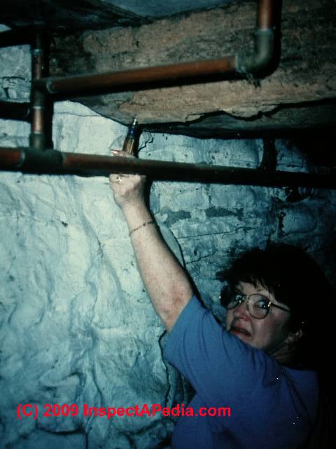
Our photo (above left) illustrates the chance involved in using even a long-pin Delmhorst moisture meter to detect an exterior wall water leak that sent water running inside the wall cavity but down the side of the stud.
None of the moisture meters we tested could find this leak until we cut open the wall.
In general, pin type moisture meters work well at producing moisture content profiles in materials that have been directly wet or dampened such as wood or drywall that are directly accessible.
Probing deep inside wall cavities, as our photo above illustrates, is a hit-or miss proposition. Electronic moisture encounters work well at producing moisture content profiles on all surfaces and can detect moisture behind a ceramic tile wall. But these devices can be fooled by foil faced insulation, expanded metal lath, piping and wiring.
Also see MOISTURE CONTROL in BUILDINGS - DF.
Are Thermal Images Reliable for Spotting Areas of Extra Risk of Structural Rot Damage or Hidden Mold in Buildings?
 OPINION: DF: Thermal images and IR have been widely used with some success at spotting areas of heat loss in buildings and these tools have a longer history of use in examining overheated electrical connections, motors, etc. But for finding hidden mold, thermography is a risky proposition.
Image at left, courtesy Paul Probett, Incodo [1]
Watch out: in the hands of the un-trained or unscrupulous these and other tools can wreak havoc or harm to consumers. The most egregious instrument snafu I've come across [DF] recently was a Hudson Valley New York "mold remediator" uses an IR camera to tell his clients where the hidden mold is located in their home - it was a modern version of the guy with the light meter who sold people replacement windows by showing clients where their heat loss was occurring - wherever there was light.
I did find areas of basement water entry and moldy insulation - in an area not addressed by the New York mold-thermographer.
Details about using thermal imaging to look for hidden mold are
at THERMAL IMAGING MOLD SCANS .
Also see FIBERGLASS INSULATION MOLD
Paul Probett adds: We had major problems with people buying thermal imagers, using ex military units and making ridiculous claims.
In 2008 I gave a power-point presentation [25] to a conference explaining how IR results can be fudged and I described the limitations of thermal imagers.
(Our staff had been through the Infraspection Institute USA on-line course to level 2 the year before).
Visual Inspection Compared with Micro-drilling for Wood Structure Assessment
Article Contents:
- WOOD BEAM MICRO-DRILLING ASSESSMENT - Micro-Drilling: Resistance drill Methods for Wood Structural Member Assessment. Incodo Testing Program of Micro-Drilling for Wood Assessment
- WOOD BEAM MICRO-DRILLING PROCEDURES - details of how micro drilling is used to assess wood structural member condition
- WOOD BEAM MICRO-DRILLING EFFECTIVENES S - Incodo study of microdrilling for wood structure assessment
Micro-drilling measures drill resistance which is related to timber density and strength.
Visual /brashness testing supported with limited microbiological testing focuses on removal of all decayed timber as the critical element in decisions.
It is suggested that – as decayed frame replacement work is work undertaken under a building consent – testing or assessment should be based on compliance documents as far as possible.
This may involve a modification of current approaches to remediation practice by reference to existing building code documents as the preferred evaluation criteria for making timber retain or re frame type decisions.
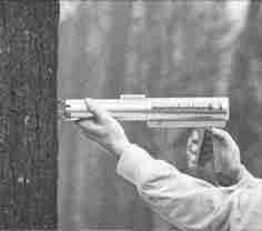
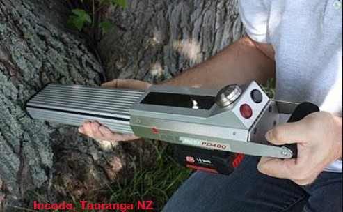
How does Micro Drilling Timber Assessment Work?

Testing involves drilling a 2 mm hole in timber members up to 300mm
The drill is computer controlled with drill bit rotation rpms and linear penetration independent of each other and at pre-set levels applicable to the timber specie. This is a change from older generation microdrills that had rpm and penetration linked and power applied controlled by the operator.
Results are readable in real time via the onboard display as the graph is formed.
Typical testing for 100 mm p.rad framing is about 15 seconds.
Results are also processed according to developed timber specie parameters and appropriate standards (where applicable) so onboard software instantly gives a preliminary pass, fail or retest assessment of timber. Settings are adjustable to assist with the identifying of quality infractions, decay areas and splits or checks.
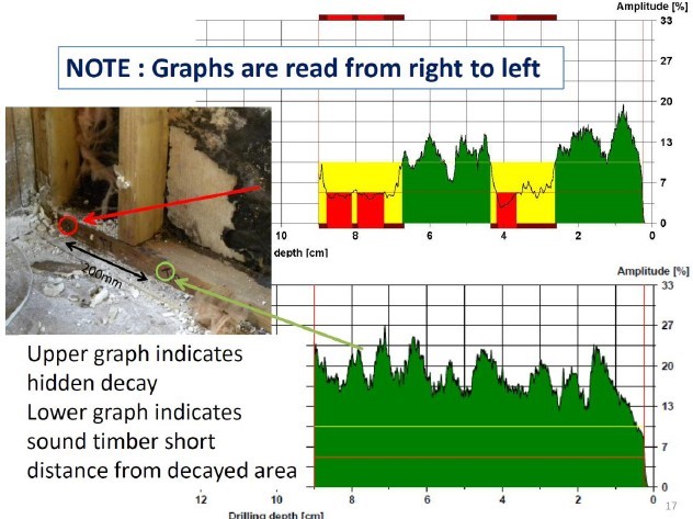
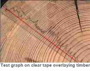
Information is then bluetoothed to a draft report and presented in a similar format to the following graphs and charts.
As highlighted in the 2010 RILEM State of the Art Report – In Situ Assessment of Structural Timber by Kasal and Tannert “ If strength values are require(d) the best drills available on the market are required as well as a high level of education and experience. This, proper education of the user is a critical point before applying resistance drilling” quote
Incodo endorse the above and suggest general usage, adjusting programmable settings interpretation and moderation of results is critical.
Micro-drilling In Situ Timber assessment
Test Results: Summary
- Base of studs where decay transmitted from wet bottom plate – timber frequently found to be sound within 150 - 200 mm possibly allowing splinting of studs rather than full replacement
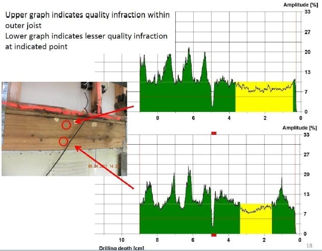
- Double timbers joists and studs – frequently decay between members but sound outer faces.
- Some surface decay has limited penetration
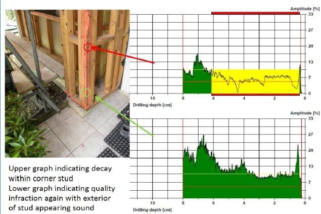
- External corner studs behind direct fix cladding can have stepped clamping point decay
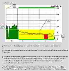
Test Results: Evaluation and Moderation
Test results indicate appreciable differences between sound and unsound timber. Noticeable anomalies on graphs indicative of issues include:
- Partial or Full loss of all or some latewood peaks.
- Smoothing of graphs along upper amplitude line affecting normal early wood and latewood norms (lower height of “saw teeth”).
- Significant variation across a graph in different area.
- General lowering of results in areas on same graph.
- Sloping shoulders as graph drops to plateau or valley.
- Sloping shoulder to graph at entry and exit points rather than near vertical step within 2-3mm of surfaces.
- Acceptable anomalies which are readily identifiable include changes induced by splits, checks, knots, junction between two timber members and pithy cores.
While software is set to handle many of these factors, moderation of individual graphs is part of the testing process and recommendations are that all reports are moderated before being provided.
Test Protocols
Recommended testing involves checking bottom plates at 1.0m centres and as close as practicable to external corners. In addition testing focuses on high risk details such as window sill corners and points below, balcony to wall connections, base of apron flashings etc and wherever staining or other concern aspects are noted.
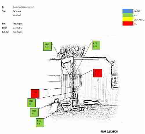
Inspection locations are plotted on a WIN 7 tablet using preloaded plans or elevations or on photos taken using the tablet’s main camera. Incodo have developed a suitable template for wirelessly transmitting data from the drill into an open report which can be prepared on the tablet or sent to the office for moderation and review.
Reports are comprehensive and targeted completion for reports is the same or following day after inspection.
Micro-drilling methodology testing for NZ timbers- A Basis
INCODO has undertaken substantial in-house testing to determine suitability of micro-drilling for assessment of low density plantation grown pinus radiata in particular.
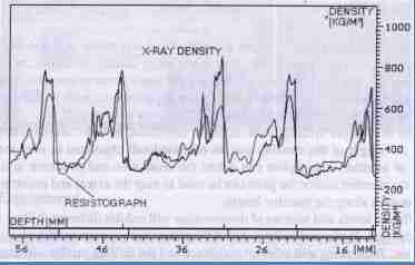
Graph highlighting close correlations between X-ray density and resistance drill readings taken using a Resistograph micro-drill.
Quoting:
Profiles of radial X-ray density and drill resistance of the same larch sample.
Rilem - State of the Art Report In Situ Assessment of Structural Timber, Bohumil Kasal & Thomas Tannert, Springer 2010. [3][4][5][6]
In addition reliance has been based on studies by others* involving micro-drilling in Europe, USA and Australia related to structural timber in buildings and bridges.
 The technology has been used for many years. The big difference is that the PD model is a new generation micro-drill with onboard firmware
*Ref www.printfu.org search “Resistograph” or “Sibtec”
Quote
“Wood density is the property which will be used as an example because of its’ close correlation with timber strength (Dadswell and Nicholls, 1959, Elliot 1970) …and because it is widely held by wood technologists to be the single most important wood variable (de Zeeuw 1965) According to Panshin et al (1963) the relationship between wood density and timber strength is expressed by
S = K (D)n
Where S is any of the strength properties, K is a constant, D is density and n is an exponent which depends on the strength property being considered”
- WOOD DENSITY OF RADIATA PINE: ITS VARIATION AND MANIPULATION – D J Cown, FRI
Incodo Testing Program of Micro-Drilling for Wood Assessment
Phase 1: Initial set up (completed)
Determining consistency of results using sound timber and establishing preliminary variable settings for software to determine Pass/Warning/Fail, Quality Infraction levels and identification of decay type voids.
Phase 2: Site testing and integration into report template (completed)
Initial site testing on buildings with wall framing exposed as part of remediation or demolition works. Three buildings – all in Auckland
Adjustment of settings for onboard software.
Build larger database of sound timber graphic levels to use as controls / base levels.
Phase 3: Outside consultant and further field testing (completed but ongoing consultation)
Consult ex FRI staff and engineers as to draft reports and use of terms.
Further testing on variety of common (and uncommon timbers incl. Matai, Pinus Syl. (Aus plantation), Pinus Rad. poles, Jarrah utility poles etc.
Determine further testing requirements.
Phase 4: Effect of moisture on consistency and reliability of test results (Completed – report at draft stage as at 05/12)
Assessment of impact of varied moisture levels on microdrilling results.
Undertake in-house testing using resistance moisture meter, H3.1 framing (to ensure no internal decay to skew results), Contherm drying oven, etc. Limited to 4 samples dried from 88-100%+MC to 12-14% Results (currently being tabulated)
Preliminary indications are that moisture level effects are limited and do not impact on micro-drilling assessments sufficiently to be of concern. (likely reason is considered to be that drill readings are a resistance reading and this is a combination reading of lateral penetrative resistance as well as shear loads required by the bit tip to slice through timber fibres at various angles to fibre orientation eg shearing occurs parallel and at random angles to timber fibre direction )
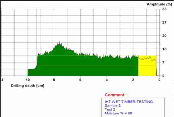
Sample 2 graph at 88.0% Moisture Content (MC) indicated
and next graph (below) at indicated 14.4%MC.
Readings taken from new SG8 pinus radiata using Protimeter resistance meter.
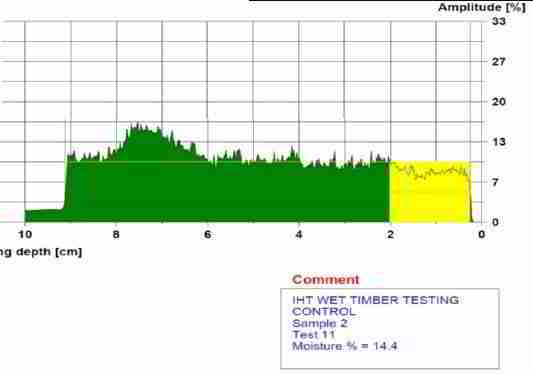
Readings taken from points at 20mm centres, along plane of timber grain to ensure minimal impact to test in regard to variance of earlywood and latewood.
Net result indicates minimal graphical difference values between high and EMC (equilibrium moisture content) approximated moisture levels.
Phase 5: Fractometer comparison with micro-drilling including relationship to compliance documents. (Equipment sourced)
Comparison between test results and timber testing properties in accord with NZS: 3622:2004.
Further testing involving taking samples from critical points in sample(s) identified by test graphs, where there is a transition from sound to decayed wood and determining the degree of correlation to timber strength when tested for compression, bending and tension using an IML Fractometer Mark
Programmed testing also involves the same methodology being applied to other timber species as samples become available and demand and demand for micro-drilling testing is required.
Specific testing involves has involved sourcing dendochronological level dry wood core drills capable of extracting parallel to grain cores to test bending stiffness.
Phase 6: Microbiological comparison with micro-drill test results in timber transitioning from sound to decayed. (Possible test methodology)
Microbiological comparison of samples and phase 5 results by independent laboratory such as Biodet.
NOTE: The value of this testing is being considered and is not currently scheduled.
Arguably the decision to retain or replace building elements in leaky homes should be driven by timber meeting or failing the requirements of NZS:3602, :3603, :3604 and :3622. These are “strength” related criteria – not decay presence criteria.
As micro-drilling is considered to evaluate strength – it becomes a moot point whether decay impact is a Building Consent / Safe & Sanitary criteria that warrants consideration.
[Click to enlarge any image]
Argument in simple terms is - if the timber meets Building Code requirements, that is all that is required to meet for compliance.
This is the same for supplied timber for remediation which is tested for strength only.
Presence of incipient, surface or minor decay is irrelevant to decisions to retain or replace as effective remediation practice should ensure future moisture levels remain at or below 18% at which level any remaining timber decay fungi reportedly cannot thrive.
Current best practice remediation also includes in situ preservative treatment and removal of decayed timber which severely limits opportunities for framing to become structurally non-compliant at a later date. (If this was not the case complete exterior frame replacement should be the norm)
Phase 7: Blind test of hidden framing (Possible Test)
Assess building ready for extensive remediation and reclad using NDT moisture meter to help determine focus points from inside only and using micro-drill to test largely through external wall skirtings and or window liners etc
Note drill used in concert with metal detector/ stud finder for safety etc
Compare report(s) with actuals after cladding removed
Watch out: for moisture meter limitations: we [DF] have tested and demonstrated that while moisture meters are an invaluable tool in assessing building conditions, none of the moisture meter designs presently on the market can reliably detect all wet or leak in conditions in all sorts of building structures and cavities.
- Moisture meters only detect current or recent leaks or moisture traps that have not dried out; past leaks and concomitant rot or insect damage in areas now dry will not be detected by a moisture meter
- Moisture meters vary in the depth to which they can sense water or moisture in a structure, depending on sensing pin length, depth to which pins are inserted into a material, or depending on the circuit design of electronic moisture meters.
A short pin moisture meter will not reliably detect moisture deeper in the wall cavity such as in the wall insulation or on the cavity side of exterior wall sheathing. Even a long pin moisture meter, probing through drywall and into wall or ceiling cavity insulation, may not detect water on the surface of exterior sheathing nor even soaking wet water rivulets running down a portion of the side of a vertical stud or timber.
It's "hit or miss" using a moisture meter as a leak screening device without the accompaniment of an expert visual inspection.
Details are at MOISTURE METER STUDY . - DF
Note: Above information is copyright, commercially sensitive and is yet to be peer reviewed. It is not to be copied or circulated without the express and written permission of Incodo Limited. Adapted here by InspectaPedia.com, with permission from Incodo 8/5/2012, technical review is in process.
V4a 06/12 - ####
...
Continue reading at WOOD STRUCTURE ASSESSMENT or select a topic from the closely-related articles below, or see the complete ARTICLE INDEX .
Or see these
Recommended Articles
- THERMAL IMAGING, THERMOGRAPHY - Mr. Probett's power point presentation on using thermography in building damage or mold surveys
- HEAT LOSS DETECTION TOOLS
- TIMBER FRAMING, ROT
- WOOD BEAM VISUAL INSPECTION
- WOOD BEAM MICROBIOLOGICAL ASSESSMENT
- WOOD BEAM FRACTOMETER TESTING
- WOOD BEAM PILODYN TESTING
- WOOD BEAM MICRO-DRILLING ASSESSMENT
- WOOD BEAM ROT ASSESS: MOISTURE METERS
- WOOD BEAM ROT ASSESS: THERMOGRAPHY
- WOOD STRUCTURE ASSESSMENT - COMBINED ARTICLE
- WOOD STRUCTURE ASSESSMENT
Suggested citation for this web page
WOOD STRUCTURE ASSESSMENT - COMBINED ARTICLE at InspectApedia.com - online encyclopedia of building & environmental inspection, testing, diagnosis, repair, & problem prevention advice.
Or see this
INDEX to RELATED ARTICLES: ARTICLE INDEX to BUILDING STRUCTURES
Or use the SEARCH BOX found below to Ask a Question or Search InspectApedia
Ask a Question or Search InspectApedia
Share this article:Try the search box just below, or if you prefer, post a question or comment in the Comments box below and we will respond promptly.
Search the InspectApedia website
Note: appearance of your Comment below may be delayed: if your comment contains an image, photograph, web link, or text that looks to the software as if it might be a web link, your posting will appear after it has been approved by a moderator. Apologies for the delay.
Only one image can be added per comment but you can post as many comments, and therefore images, as you like.
You will not receive a notification when a response to your question has been posted.
Please bookmark this page to make it easy for you to check back for our response.
IF above you see "Comment Form is loading comments..." then COMMENT BOX - countable.ca / bawkbox.com IS NOT WORKING.
In any case you are welcome to send an email directly to us at InspectApedia.com at editor@inspectApedia.com
We'll reply to you directly. Please help us help you by noting, in your email, the URL of the InspectApedia page where you wanted to comment.
Citations & References
In addition to any citations in the article above, a full list is available on request.
- [1] Paul Probett, Clinton Craig, Blake Probett, "An Introduction to Micro-Drilling Technology for N. Z. Structural Timber Assessment", Incodo Ltd , 4/511 Cameron Rd, Tauranga NZ, article adapted by InspectAPedia with permission, August 2012. Contact the authors by Email: Paul Probett, mail2us@incodo.co.nz , Tel: 027 28 000 36 (Mobile) Website: https://www.incodo.co.nz/ [Copy of this article on file as Microdrilling_Assessment_Incodo.pdf]
Quoting from the Incodo website the company describes its services:
- Incodo Forensic Building Pathology:
The Forensic Building Pathology division provides evidence in report form to government agencies, consultancy firms, lawyers and others, when truly independent analysis based on comprehensive testing is required. Incodo arguably has the largest, most up-to-date and comprehensive range of building investigation equipment available and has developed unique methodologies particularly in the field of non-destructive testing for leaking structures. - Incodo In situ Timber Assessment:
The in-situ Timber Assessment division provides a service whereby technicians use state-of-the-art timber resistance drill technology to profile variations in timber density associated with timber decay.
The work is done on site and the results are instant.
This technology is objective and evidential in nature and provides assessment as to whether wood is significantly decayed, suspect or suitable for retention. The technology has particular application in locating and assessing hidden decay.
- Incodo Forensic Building Pathology:
- [2] Thomas Tannert, Andreas Muller, Mareike Vogel, "Applications and limitations of NDT: a timber bridge case study", NDTCE’09, Non-Destructive Testing in Civil Engineering
Nantes, France, June 30th – July 3rd, 2009, web search 8/3/2012, original source: http://www.ndt.net/article/ndtce2009/papers/144.pdf [copy on file as Tannert_Timber_Test_144.pdf]
Abstract
The applications and limitations of different non-destructive and semi-destructive techniques to evaluate the structural integrity of timber members in a pedestrian bridge are presented as a case study. Sophisticated assessment tools are required to detect hidden damages in timber structures: for example stress-wave techniques are used to evaluate the modulus of elasticity of bending members and resistance to drilling is used to gain knowledge of areas of changed density due to insect or moisture induced damages. Reliably relating the gathered data to the structural integrity of the structure is a complex issue. Bending members and connection details of a decommissioned timber bridge were evaluated using non destructive assessment tools. Eventually these parts were tested destructively to assess their remaining modulus of elasticity and load bearing capacity. The need for improvements in the current practice is highlighted by comparing the results from the non-destructive, semidestructive and destructive tests. - [3] Bohumil Kasal, Thomas Tannert, "RILEM Technical Committee on In Situ Assessment of Structural Timber", Bohumil Kasal et al., 2010, Advanced Materials Research, 133-134, 271, Abstract: Timber is an intriguing structural material and the only one that is truly renewable. Being biodegradable, hygroscopic and non-isotropic, it presents special challenges when assessing its integrity in structures. The presented paper outlines the major issues related to in-situ evaluation of structural timber and summarizes the work of the RILEM Technical Committee 215-AST “In-situ assessment of structural timber”. The committee was established in 2005 to bring together leading scientists and practitioners in the field of evaluation of timber in existing structures. Timber structures have been investigated for decades using numerous techniques that have been either developed specifically for the material or were transferred from other fields of investigation. A state-of-the-art report describing existing and emerging technologies and methods was prepared by the RILEM committee. The report describes the principles, the applications and the limitations of major evaluation techniques for in-situ assessment of timber. A brief discussion of codes standards and future research needs shows that much needs to be done in this area. As a present activity, harmonized test procedure recommendations are being prepared that will provide the engineering community with valuable guidance when evaluating timber structures.
- [4] Bohumil Kasal & Thomas Tannert (Editors), In Situ Assessment of Structural Timber, ISBN 978-94-007-0559-3, Rilem 2010
- [5] Bohumil Kasal, Tension Micro Specimens,
In Situ Assessment of Structural Timber
RILEM State of the Art Reports, 2011, Volume 7, 75-80, DOI: 10.1007/978-94-007-0560-9_8, [excepts chapter 7 on file: Tension Micro-Specimens, as Kasal_Testing.pdf]
Abstract The principle of this method is extracting triangular specimens (about 5 mm equal-sides triangle) along the length of the member. Small-kerf circular saw with a fixture attached to the surface of the member is used to extract the specimens. Specimens are then glued to the test blocks and tested in tension. The method gives direct values of tensile modulus of elasticity and strength for clear wood. The values are local and pertain to the tested area and surface.
[From chapter 7.1 Background: This method was developed by Kasal and is based on direct measurement of tension properties along fibers. Bending strength evaluation is an important aspect of in situ evaluation of timber members as it is one of the predominant modes of loading, but estimates of the bending properties in situ can present a challenge. With information on the member's tensile properties, bending strength estimates can be made; tensile strength has been related to bending strength and is considered to be approximately equal. Tensile properties have a poor correlation with compression properties therefore tensile strength can not be estimated using information attained with the core drilling technique. Specimens can however be extracted to evaluate the tensile properties of in situ members with the technique described in the following sections....'] - [Also] Kasal B, Anthony R: Advances in in-situ evaluation of timber structures. Progress in Structural Eng and Materials. 6(2):94-103, 2004.
- [6] Thomas Tannert, Andreas Müller, Mareike Vogel, "in-situ assessment, hot spots, moisture content, block-laminated timber", ICTB 2010, Bern University of Applied Sciences. ISBN 978 8251 926805, in-situ assessment, hot spots, moisture content, block laminated timber,
Abstract:
Timber has been a structural material for bridges for centuries and numerous examples throughout the world demonstrate its durability. But timber is biodegradable and hygroscopic and regular inspections are recommended to determine the condition of the structure. This paper reports on the structural health monitoring of timber bridges in general and the long term moisture measurement inside block-laminated timber elements of several traffic bridges in specific. Presently there is no reported scientific information available on the long-term moisture behaviour and the resulting moisture induced stresses and dimensional changes of block-laminated timber elements. The paper reports on the monitoring of the moisture content of a block-laminated timber bridge.
[References 7-13 below are cited from this document] - [7] Wilkinson K, Thambiratnam D, Ferreira L. Non Destructive Testing of Timber Bridge Girders. In Proceedings Int. Conf. on Structural Condition Assessment, Monitoring and Improvement, Perth, Australia, 2005.
- [8] Kasal B, Anthony R: Advances in in-situ evaluation of timber structures. Progress in Structural Eng and Materials. 6(2):94-103, 2004.
- [9] Gerold M. Bloc-Glued Laminated decks for timber bridges. Structural engineering international, 12(3): 214–217, 2002.
- [10] Graham T. Overview of non-destructive evaluation technologies. In Proceedings of the Nondestructive Evaluation of Aging Bridges and Highways, Ed by S. Chose, 1995.
- [11] Duwadi SR, Ritter MA. An Overview of the Wood in Transportation Program in the United States, In Proceedings 5th World Conference on Timber Engineering, Montreux, Switzerland, 1998.
- [12] Rinn F, Schweingruber FH, Schär E. Resistograph and X-Ray Density Charts of Wood. Comparative Evaluation of Drill resistance Profiles and X-Ray Density Charts of Different Wood Species. Holzforschung 50:303-311, 1996.
- [13] Brashaw B, Vatalaro RJ, Wacker JP and RJ Ross. Condition Assessment of Timber Bridges: 1. Evaluation of a Micro-Drilling Tool. Gen. Tech. Rep. FPL-GTR-159. Forest Products Laboratory Madison, WI. 2005.
- [14 Simpson W. Drying and Control of Moisture Content and Dimensional Changes. Chapter 12, Wood handbook - wood as an engineering material. General Technical Report FPL–GTR– 113. Forest Products Laboratory, WI, 1999.
- [15] "Fractometer Print Manual", IML Instrumenta Mechanik Labor System GmbH Großer Stadtacker 2 69168 Wiesloch • Germany, 02-2008, web search 8/4/12, original source: http://www.imlusa.com/Fractometer_Print_eng_web_A4.pdf [Copy on file as Fractometer_Print_eng.pdf]
- [16] Bob Monk, "Evaluation of Decay Detection Equipment in Standing Trees", USDA Forest Service, web search 8/4/12, original source http://www.fs.fed.us/eng/techdev/IM/tree_decay/tree_decay_detect_equip.shtml [Copy on file as Monk_Tree_Deday_Detection.pdf] Introduction - quoting:
A project was proposed to test and compare several of the devices that are able, to some degree, to detect decay in trees. Decay in trees is directly related to the hazards that they present. However, detection of decay does not necessarily mean that a tree is hazardous. The identified devices can be used to determine what decay is present. It is still necessary to use professional experience and sound judgment to decide if a tree actually poses a hazard. General guides or "rules of thumb" can also be used, such as Guidance notes from the Minnesota Department of Natural Resources and the USDA Forest Service, 1996 that suggests a 25 mm ring of sound wood is required for every 150 mm of stem diameter at any point on the stem. If the proportion of decayed wood to sound wood exceeds this level then action may need to be taken to minimize the hazard posed by the tree (Lawday and Hodges, 2000). [Additional selected citations from this article are below]- [16a] Larsson, B.; Bengtsson, B.; and Gustafsson, M. 2004. Nondestructive Detection of Decay in Living Trees. Tree Physiology. 24: 853-858
- [16b] Moore, W. 1999. The Combined Use of the Resistograph and the Shigometer for the Accurate Mapping and Diagnosis of the Internal Condition of woody Support Organs of Trees. Arboriculture Journal. 23: 273-287
- [16c] Nicolotti, G.; Socco, L.V.; Martinis, R.; Godio, A.; and Sambuelli, L. 2003. Application and Comparison of Three Tomographic Techniques for Detection of Decay in Trees. Journal of Arboriculture. 29(2): 66-77
- [16d] Seavey, R.; and Larson, T. 2002. Inspection of Timber Bridges. Minnesota Department of Transportation Technical Report MN/RC-2002-34. St. Paul, MN. 43 p.
- [16e] Wang, X.; Divos, F.; Pilon, C.; Brashaw, B.K.; Ross, R.J.; and Pellerin, R.F. 2004. Assessment of Decay in Standing Timber Using Stress Wave Timing Nondestructive Evaluation Tools: A Guide for Use and Interpretation. Gen. Tech. Rep. FPL-GTR-147. Madison, WI: U.S. Department of Agriculture, Forest Service, Forest Products Laboratory. 11 p.
- [17] Pilodyn Wood Tester, USA / Canadian Source: Intech-NDE, 6211 Roper Road
Edmonton, Alberta
T6B 3G6, Tel: 1 888-576-7756 or Intech-NDE, 140 - 8851 Beckwith Road
Richmond, B.C., Tel: 1 800-677-8884, or USA Tel: 800-297-3208, Website: http://www.intechnde.com, web search 8/4/12, original source: http://www.corvib.com/pilodyn/ Quoting:
Pilodyn is an easy-to-use wood testing instrument which is suitable for trees, railway ties and utility poles. The Pilodyn wood tester (Hylec Controls) is described by and currently available in North America from InTech/NDE U.S. Tel: 905-716-5604 / 800-297-3208, or Email: bnadeau@intechnde.com - [18] Pilodyn Wood Tester, Hylec Controls, available in Australia from Ferret http://www.ferret.com.au/n/Pilodyn-wood-density-meter-from-Hylec-n852069 - Quoting:
Pilodyn, available from Hylec Controls , was developed to determine the density and strength of dead and living wood. Invisible soft rot can be detected rapidly and objectively in an easy non-destructiveway and the reduction in strength associated with it can be determined. This can be of vital importance in the case of wooden playground structures,climbing frames and telephone masts.
With PILODYN 6J Forestversion the density of the wood is determined on living trees. The damage is so little that the tree suffers no harm and the testing method is regarded as non-destructive.
Testing procedure: The testing procedure is very simple: The tester is loaded with the ramrod and then pressed firmly onto the tet surface. The impact pin is shot into the wood by pressing the trigger cover. The depth of penetrationcan be read straightaway in mm on the scale mounted on the tester.
Typical applications of the Pilodon:
Testing the stability of wooden structures on playgrounds, detection of soft rot
Testing the strength on wooden telephone masts, detection of soft rot
When thinning out: sorting out trees with undesirable density of the wood
Early detection of diseases: periodic measurement detects unnatural changes in the wood density
Comparison of the location-dependent density to determine the optimal location for the respective tree species
Establishing productivity with respect to density for the same tree species and similar location properties for culture purposes Testing and sorting of cut wood into timber classes - [19] Hylec Controls, 8 Melissa Street AUBURN NSW 2144 AUSTRALIA, Tel: 1300 522 004, Email: sales@hyleccontrols.com.au, http://www.ferret.com.au/c/Hylec-Controls
- [20] Brashaw, Brian K.; Vatalaro, Robert J.; Wacker, James P.; Ross, Robert J. 2005. "Condition Assessment of Timber Bridges: 1. Evaluation of a Micro-Drilling Resistance Tool " Gen. Tech. Rep. FPL-GTR-159. Madison, WI: U.S. Department of Agriculture, Forest Service, Forest Products Laboratory. 8 p., web search 8/5/2012, original source: http://www.fpl.fs.fed.us/documnts/fplgtr/fpl_gtr159.pdf [copy on file as Micro_Drill_Study_USDA_fpl_gtr159.pdf] This publication is also available from the U.S. FPL at www.fpl.fs.fed.us
Abstract:
The research presented in this report was conducted to evaluate the accuracy and reliability of a commercially available micro-drilling resistance device, the IML RESI F300-S (Instrument Mechanic Labor, Inc., Kennesaw, Georgia), in locating deteriorated areas in timber bridge members. The device records drilling resistance as a function of drilling depth, which allows the operator to assess the location of deterioration in the member cross section. Bridge components containing different levels of natural decay were used as test specimens in this study. The IML RESI F300-S was first used to assess decay in the timber bridge specimens. The specimens were then sawn along their length into slabs to expose their interior condition. The interior faces of these slabs were inspected visually and with a stress-wave probe to confirm if deterioration was present. On the basis of these tests, we conclude that this micro-drilling device accurately determines if deterioration is present at the point at which the test is performed. Keywords: timber, bridges, inspection, drilling resistance, nondestructive evaluation
Excerpt from the study's conclusions:
Based on our tests, we offer the following comments about the accuracy of using the IML RESI F300-S for locating deterioration in bridge timbers:
1. The tool is accurate at determining the presence of decay in timber bridge specimens. However, these data are limited to the drilling location.
2. The tool can precisely locate an internal defect (decay pocket, check, or split) within the member’s cross section. This can be advantageous for condition assessment and load rating purposes.
3. Decay indices were developed for Douglas-fir timbers as follows: sound, >25% resistance; moderate decay, 10–25%; and advanced or severe decay, 0–10%.
One drawback is that multiple, time-consuming drilling would be required to map the area and extent of the decay in the other plane. Another possible drawback is the potential to spread the decay to sound areas within a timber or to sound timbers by multiple use of a contaminated drill bit. Routine cleaning of drill bits, or replacement with a new one, would greatly reduce this potential drawback.
It is crucial to use this or any nondestructive testing tool or device as part of a comprehensive condition assessment. Such an assessment should incorporate an in-depth visual inspection, knowledge of prior use of the structure, and a working knowledge of fundamental engineering properties of structural wood products. This technique, when used in concert with visual and ultrasound techniques, would provide a very accurate description of the condition of timbers. - [21] Brashaw, B.K.; Vatalaro, R.J.; Erickson, J.R.; Forsman, J.W.; Ross, R.J. 2004. Final Report: A Study of Technologies to Locate Decayed Timber Bridge Members. Project No. 187-6456, NRRI/TR-2004-06. Duluth, MN: UM-Duluth, Natural Resources Research Institute.
- [22] Brashaw, B.K.; Vatalaro, R.J.; Ross, R.J.; Wacker, J.P. 2005. Condition Assessment of Timber Bridges: 2. Evaluation of Several Commercially Available Stress Wave/Ultrasonic Tools. Gen. Tech. Rep. FPL-GTR-160. Madison, WI: USDA Forest Service, Forest Products Laboratory.
- [23] Ross, R.J.; Brashaw, B.K.; Wang, X.; White, R.H.; Pellerin, R.F. 2004. Wood and Timber Condition Assessment Manual Madison, WI: Forest Products Society. 74 p.
- [24] Troltech GMBH & Co. KG. Deutchland, Grebbener Str. 7, D-52525 Heinsberg, Deutchland, produces the Trotec T2000, Tel: 02452 962-450, International: +49 2452 962-450, Email: online@trotec.de, Website: http://www.trotec.de/, Web page for the Troltec T2000: http://www.trotec.de/en/product-catalog/measuring-instruments/multi-function/t2000/
- [25] Paul Probett, Incodo, Ltd., "Thermal Imaging and Building Surveying / Inspection" 2008, Incodo Ltd , 4/511 Cameron Rd, Tauranga NZ, article adapted by InspectAPedia with permission, August 2012. Contact the authors by Email: Paul Probett, mail2us@incodo.co.nz , Tel: 027 28 000 36 (Mobile) Website: https://www.incodo.co.nz/ [Copy of this article on file as Thermal Imaging NDT Presentation 2008.ppt ]
- In addition to citations & references found in this article, see the research citations given at the end of the related articles found at our suggested
CONTINUE READING or RECOMMENDED ARTICLES.
- Carson, Dunlop & Associates Ltd., 120 Carlton Street Suite 407, Toronto ON M5A 4K2. Tel: (416) 964-9415 1-800-268-7070 Email: info@carsondunlop.com. Alan Carson is a past president of ASHI, the American Society of Home Inspectors.
Thanks to Alan Carson and Bob Dunlop, for permission for InspectAPedia to use text excerpts from The HOME REFERENCE BOOK - the Encyclopedia of Homes and to use illustrations from The ILLUSTRATED HOME .
Carson Dunlop Associates provides extensive home inspection education and report writing material. In gratitude we provide links to tsome Carson Dunlop Associates products and services.
 |
HOME | ABOUT | ASK a QUESTION | CONTACT | CONTENT USE POLICY | DESCRIPTION | POLICIES | PRIVACY | |
| © 2026 - 1985 Publisher InspectApedia.com - Daniel Friedman | |||||||||