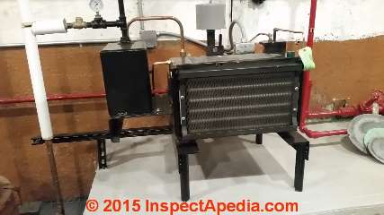
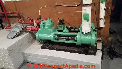
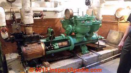
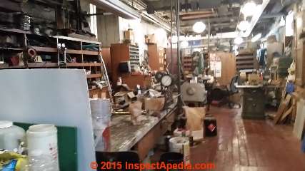
 Pratt Institute Engine Room / Pratt Steam Room
Steam Boilers, Steam Generators, Equipment, Controls, History in more than 50 photos & videos
- POST a QUESTION or COMMENT about residential steam heating system controls, valves, gauges
What's in the Pratt Institute Steam Facility? a photo guide to antique & still operating, steam equipment & controls, electrical generators, even sections of New York City's very first underground DC electrical cabling:
The steam system at Pratt in Brooklyn is a veritable steam museum containing working steam boilers, electrical generators, and a myriad of equipment and steam controls most of which are antique and most of which have been restored and kept working by Chief Engineer Conrad Milster.
The principal equipment in the steam facility or "Pratt engine room" has been in place since 1889. This article series documents the Pratt steam room equipment and explains the use and operation of much of the equipment.
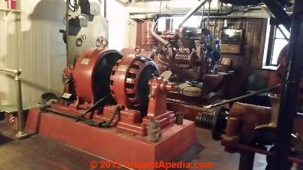
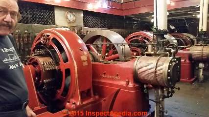
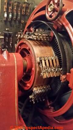
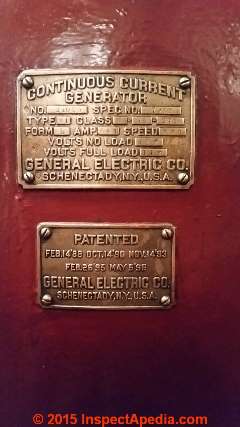
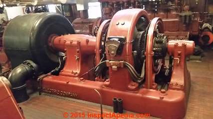
The original DC electrical generator manufactured by General Electric and shown above carries patents dating to 1896.
This article series is an ongoing effort to document and preserve some of the encyclopedic knowledge of Mr. Milster who has worked the facility since 1958 and has served as Chief Engineer since 1965.
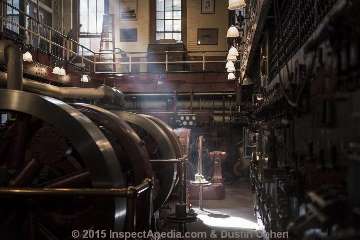
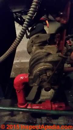
Here we document and explain some of the equipment and controls. Page top photos, one of the original DC generators in the Pratt steam room, photographed in 2015.
Notice: neither the authors/editors of this article nor the hosting website InspectApedia.com has any affiliation with the Pratt Institute.
InspectAPedia tolerates no conflicts of interest. We have no relationship with advertisers, products, or services discussed at this website.
- Daniel Friedman, Publisher/Editor/Author - See WHO ARE WE?
Steam Boilers, Controls Generators & Steam Systems at the Pratt Institute
Pratt Institute's steam room hosts multiple steam boilers and steam powered generators of considerable size. The facility is a living museum of steam generators, steam power, and steam heating equipment meticulously restored and maintained by Conrad Milster.
[Click to enlarge any image]
The first commercially successful steam ship, Robert Fulton's Clermont, was powered by a reciprocating steam engine: steam pressure forced pistons up and down to rotate a crankshaft. Reciprocating steam engines were inherently limited in speed and reliability: they were noisy, wet, and vulnerable to the stresses of having to convert an up-and-down or reciprocating piston movement to rotating motion through the crankshaft.
It was London-born Charles Parsons, the inventor of the steam turbine, who demonstrated the superior design of a turbine engine: steam forced through blades of the turbine rotates the engine shaft to power whatever the engine is driving: in Parsons' case, a small ship.
In June, 1897, Parson's steam-generator-driven Turbinia, the first ship to be powered by a steam engine, flashed by the royal navy as the navy was showing their stuff at Queen Victoria's 60-year jubilee celebrations.
As the navy zipped along at somewhere near a top speed of less than 20 knots, Parson's Turbinia flew by the fleet at 34 knots, running rings around the fleet and out-manuvering vessels sent to stop her.
Parson's steam-generator-driven Turbinia was a long narrow ship, about 100 ft. x 9 ft. beam giving a very fast aspect ratio. But it was his steam turbine that made the ship the fastest in the world. In the following year the British Admiralty ordered their own steam turbine powered ships.
While Charles Parson's steam turbine powered ship ran rings around the steam-powered reciprocating-engine driven British fleet, steam turbine operated electrical generators were already at work. Parson had invented the steam turbine engine in 1884. (Gordon 2016)
For U.S. enthusiasts of the history of steam power, easier than trying to find the Turbinia, or the 1906 HMS Dreadnought, just stop by the Pratt Institute in Brooklyn, New York for a look at the Institute's steam-driven electrical generators.
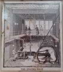
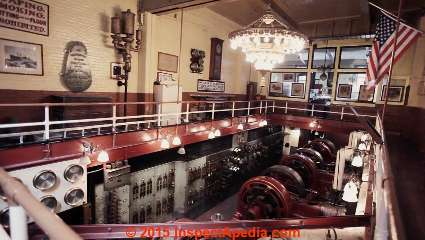
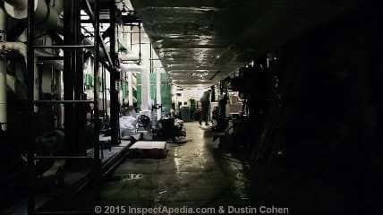
Above: the Pratt Institute Engine Room or "Steam Plant" before 1900 (first illustration) and today (second image). Immediately above as an excerpt from his video, and again below, these stunning images of the Pratt Institute steam room are provided courtesy of NY photographer / director Dustin Cohen, producer of Conrad and the Steamplant.
Several more of Mr. Cohen's photographs or images from his video are included in this article about the Pratt Institute Engine Room also referred to as the Pratt Steam Room.
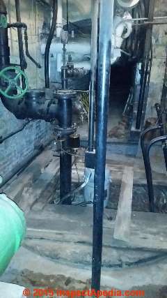
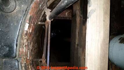
For more than 100 years the well shown just below has provided a backup water supply for the institute's steam boilers and thus for its electrical generation system. The well also supplies a rooftop water tank that in turn supports both a fire sprinkler system and in times of drought, might be used to water Pratt's lawns.
When Chief Engineer Conrad Milster pointed out those features the well was left alone. More about the well, the steam facility and its features follows.
Recently Pratt Institute authorities were considering abandoning an antique 95 foot deep well located in the floor of a chamber of the steam facility located on Pratt's Brooklyn NY Campus.
[Click to enlarge any image]
1. Above: that plank spans the opening of a hand-dug 95-foot deep well that supplies water for fire protection and lawn sprinklers on the Pratt Campus. - C.M.
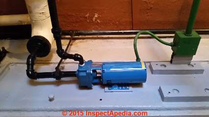
The blue pump motor atop the pump drive shaft is visible in the center of the photo, though partly obscured by the vertical pipe.
Suggested captions for all of these photos are invited - use the page top or bottom CONTACT link and refer to the photograph number in your comments. Thanks. DF.
These photographs and notes are dedicated to Conrad Milster, Chief Engineer at the Pratt Engine Room whose stunning generosity welcomes visitors interested in steam power, cats, mechanical engineering, history of electrical power distribution, and probably much else.
Conrad has worked in the Pratt Institute Engine Room since June of 1958. He was introduced to the Pratt Institute Engine Room facility by his high school machine shop instructor.
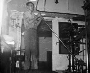
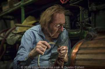
Below: Mr. Milster early in his career in the Pratt Institute "steam room". Photo provided through NY photographer / director Dustin Cohen, producer of Conrad and the Steamplant.
At the time of the photographs in this article (2015) Mr. Milster, at 80, was still serving Pratt as the Engine Room's chief engineer.
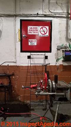
2. Above: the entrance to the fuel tank room. Oil is No. 2 and is used as a back up fuel for piped-in natural gas. - C.M.
The 18,000 gallon oil tank stores backup fuel for the three Pratt Engine Room burners firing its three steam boilers. Originally such boilers would have been fired by coal.
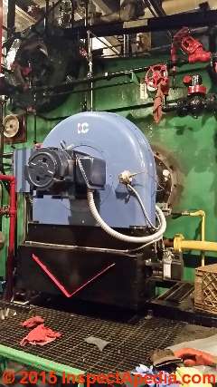
3. Below: the burner at one of the three steam boilers in the Pratt Engine Room. This is is a newly [2014] converted gas burner for the No. 3 boiler. - C.M.
The three room-sized steam boilers run individually and at variable firing rates depending on the Institute's needs. The steam system is a high pressure steam operation running at a nominal 100 psi but able also to provide low pressure steam where needed.
Steam in turn could in the past and can even today operate electrical power generators located in the same facility.
At the time of my visit in November 2015 one boiler was in operation, running at about 90 psi. Conrad explained that because the boiler needs tube rebuild and other service he was keeping the pressure a bit lower than maximum.
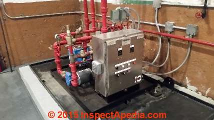
4. Below: gas supply for the gas burner at the No. 3 boiler. - C.M.
Today the Engine Room and its staff serve as the maintenance shop for HVAC and heating for the Pratt Institute.
The group maintains a system of pumps that circulates hot water in the Pratt Institute buildings as well as a network of condensate return pumps necessary for the campus steam heat distribution network to operate successfully.
5. Below: air compressor for oil atomization for the No. 3 boiler.
Conrad, born in New York City and raised in Astoria, Queens, married Phyllis in 1967 and the couple moved to a house on the Pratt Institute campus. After Phyllis passed away (ca 2009) Conrad continued to serve Pratt in his role as Chief Engineer. When he relocated (ca. 2012) to his present Pratt townhouse home, hoping to find a new place for them, Conrad was able to bring along boxes of hundreds of books that the library was discarding.
6. Below: auxiliary steam opeated fuel oil pump, ca. 1926. This pump was brought from the steam plant at 165 Broadway in New York City. - C.M. .
7. Below: rack of pipes formerly stored in racks in the oil tank room. These will be relocated when all inspections are completed. - C.M.
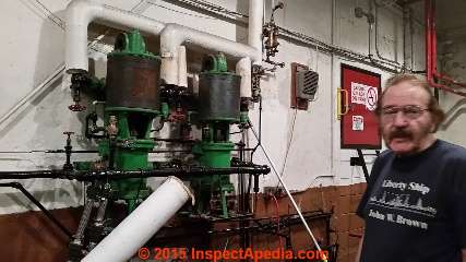
8. Below: steam-operated oil pump installed in 1906.
This is the main boiler feed pump for winter loads. The pump was built in 1906 and was rescued from Steam Plastn NO. 165 in 1965. - C.M.
Conrad's observation that part of his appreciation of these old machines is that they are reliable is supported by seeing that these machines are still working today.
They would not be if Mr. Milster had not been able to (and actually enjoy) fabricating repair or replacement parts for machines some of which were installed in 1900. As he puts it in Dustin Cohen's video, "Having the part go in and work... that's sort of interesting".
See this STEAM POWERED OIL PUMP in OPERATION VIDEO [136 MB mp4 file] to view this very steam-powered oil pump in operation. Free for viewing, not for copying nor redistribution without permission, this film is © 2015 InspectApedia.com
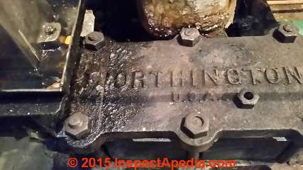
9. Below: pump detail: this is the valve chest cover for the main feed pump. - C.M.
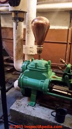
10. Below: Photographs 10-13 illustrate the air chmaber of a small feed pump. This chamber is formed from sheet copper and has been relocated from an 1888 fire pump. - C.M.
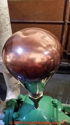
11: Above and below: The thin copper sheets that were hammered and welded or soldered to make the small expansion tank shown here are still polished and beautiful today as in 1888 when this air chamber was first used on a fire pump.
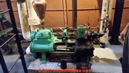
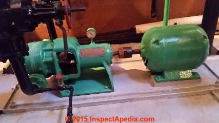
12. Above: a more complete view of the feed pump assembly.
13. Above: pump detail: this globe or air chamber, acts as a small expansion tank and as Milster points out, was originally oin an 1888 fire pump.
Himself a collector of mechanical artifacts, pressure gauges, name plates, steam whistles and similar devices,
Conrad's skill as a machinist has enabled him to restore and preserve not just items in his collection but the controls, dials, gauges, and devices that populate the Pratt Engine Room as well. Together we admired the hand-made copper expansion bulb shown above, noting that its seams remain perfectly smooth.
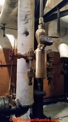
14. Above: control detail: this is a hydrostatic lubricator on the small feed pump shown above. - C.M.
We share the opinion that in an era when the number of machines, steam engines, pumps, and similar devices was still small and machines were hand-made, considerable care and thought went into the fabrication of the equipment. That probably explains why today, a century later, many observers see beauty in these old engines.
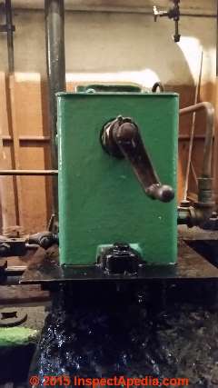
15. Above: this is a mechanical lubricator on the small feed pump. - C.M.
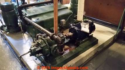
16. Above: a large electric feed pump. - C.M.
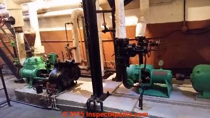
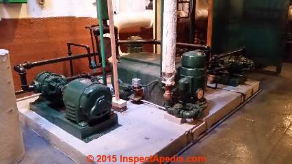
17. Above and below: Multiple generations of pumps, small steam operated and large electrically powered feed pumps. - C.M.
The types of pumps in the Pratt engine room include fuel oil pumps for the oil burner-fired steam boilers, water pumps, condensate return pumps, and perhaps something else I missed.
18. Above: at left: a large electric feed pump; at right, a small electric feed pump. - C.M.
Gauges, Indicators, Dials
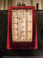
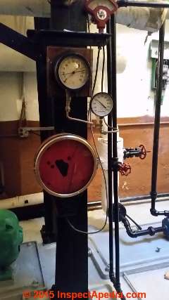
Below: This multi-dial gauge provides critical information used to assure safe and proper function of the oil burners used to heat water to steam in the Pratt Engine Room steam boilers. Provided courtesy of NY photographer / director Dustin Cohen. From left to right, this gauge measures windbox pressure, furnace draft and uptake draft. Here the term "furnace" is being loosely applied as these are boilers. (Furnaces heat air, boilers heat water.) The center gauge or "furnace draft" on most oil burners is measured in the combustion chamber right over the burner and is a critical data point. If we lose negative draft here (negative meaning there is an updraft at the fire) the oil burner will not operate properly and accumulating soot will lead to a failure of the system.
More about draft regulation is at DRAFT REGULATOR, DAMPER, BOOSTER
and also at DRAFT MEASUREMENT, CHIMNEYS & FLUES where we show how draft is measured.
In his own home Conrad has restored and installed antique but still working gauges that monitor the steam pressure in his home, city water pressure, and other measures.
You can see Conrad explaining these in Dustin Cohen's video "Conrad and the Steam plant" cited at the end of this article.
19. Above: Gauges for the feed pumps. - C.M.
Below: more pumps.
20. Above: Pump, small electric feed pump for fuel oil for the oil burners. - C.M.
21. Above: these are condensate return pumps. - C.M. In the center of the photo you can see a condensate accumlator.
22. Above: pumps (looks to me like a condensate return system]
23. Above: Conrad explains
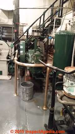
24. Above: This air compressor was originally in the Engineeing Labs and dates [we think] from the late 1920's. - C.M.
See this PRATT ENGINE ROOM VIDEO [97 MB mp4 file] of the machine above in operation. Free for viewing, not for copying nor redistribution without permission, this film is © 2015 InspectApedia.com
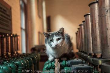
Below: I think this is a gang of check valves and air vents on hot water piping. And of course it's a cat.
The photographs above and immediately below of the Pratt Institute steam room are excerpted from the video by NY photographer / director Dustin Cohen, producer of Conrad and the Steamplant and are used here with permission.
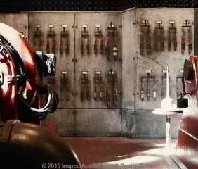
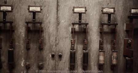
Above and in detail below: these are some of the switches controlling the circulation of hot water to various buildings on the Pratt Institute Campus. This image is excerpted from the Cohen video cited just above.
Each switch controls a pump used to circulate hot water. In detail below you can see the cartridge fuses in line just below the 240V toggle switch that turns a pump on or off.
Switches are labelled with Pratt Institute building names:. Shown below switches serve Pratt's Annex Building Halls, East Building Halls, [un-labelled], Engineering Machine Building Halls, Chemistry Building.
Where no fuses are in place, that hot water circulator is not in operation.
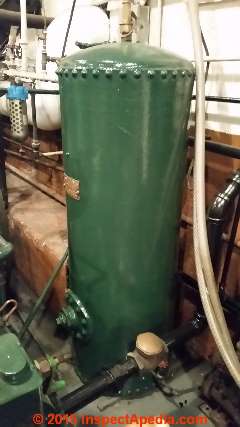
25. Above and below: Tank, Chicago Pneumatic. In the photo above at the bottom of the image is a brass check valve.
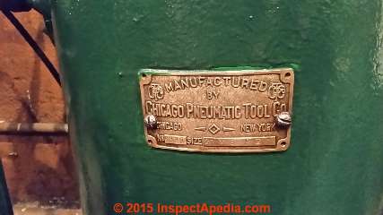
26. Above: tank plaque
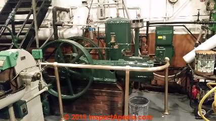
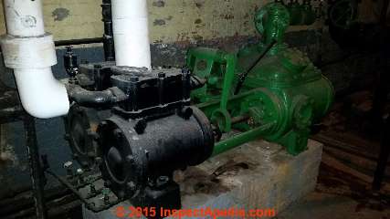
27. Above: Steam air compressors. At left the compressor was made in 1896. The nearly identical model at right in the photo is from 1906. - C.M.
28. Above: Another view of the air compressor illustrated in photo #24 and seen operating in this PRATT ENGINE ROOM VIDEO.
The passage illustrates the carefully-polished brass and painted equipment.
Conrad explains that "back in the day" when the steam room employed a full time oiler it was the oiler's job to keep the machinery wiped and polished.
That job is of more than cosmetic import: oil, water or steam leaks become apparent quickly on clean equipment, making it possible to find and fix leaks before they become catastrophes.
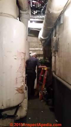
29. Above: Alley behind the engine room showing an exhaust oil separator - C.M.
This is one of the more accessible tunnel / passages in the Engine Room - it's hardly one room.
Low Pressure Steam Regulation from the Pratt Engine Room Steam System
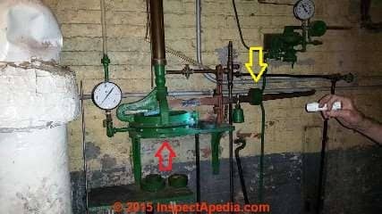
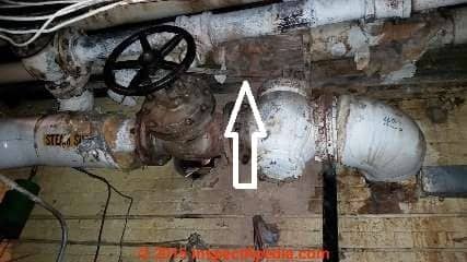
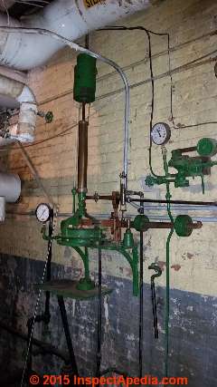
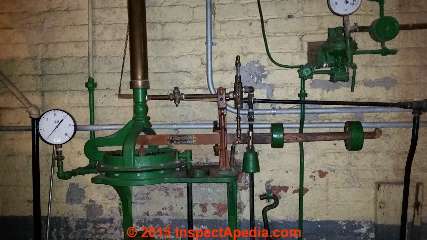
30. Above and in additional details below through photo #33: pressure contro for the low-pressure steam system. - C.M. This device is used to convert from high pressure steam to low pressure steam.
31. Above: High pressure steam operates an elegantly simple diaphragm type regulator that releases steam at low pressure into a low pressure steam piping system
. The white arrow points to the steam metering valve operated by the regulator assembly.
32. Above: High pressure to low pressure steam control, showing more of the system.
33. Above: Notice the adjustable counterweight that controls the response of the diaphragm to steam pressure PSI.
34. Above: 1887 fire pump, not in service. - C.M.
The Pratt Engine Room Well
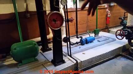
35. Above: This is the Pratt Engine Room dug well
36. Above: The actual water pump is 95 feet below grade; the hole is 45 feet deep. This system supplies water for fire protection and lawn sprinklers on the Pratt Campus. - C.M.
Peering into the hand dug well that we can just see light reflecting from the top of the water column. This well might also have been the original water supply for the Pratt steam boilers.
This well and pump are still functional. The three-phase motor that operates the water pump sits atop the well.
From that position a vertical drive shaft reaches down to the pump in the well static head.
The electric motor that operates the pump via a long vertical shaft is just visible at the right side of this photo.
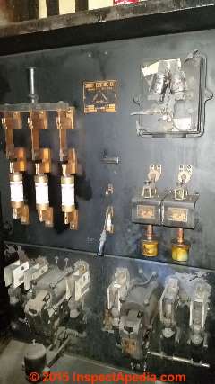
37. Above: first view of the fuse panel controlling the well pump system for the well shown above.
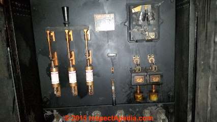
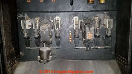
The pump switching system has a two -speed start-up procedure in order to avoid breaking the very long pump shaft by the torque that would be imposed by the pump motor if it ran up to speed too quickly. Only a brief but still critical delay between speeds is essential.
38. Above: Well pump control panel details. The system is still functional.
39. Above: The two sets of electrical relays are used to achieve the two-step well pump motor start-up sequence.
Steam Operated Condensate Return Pump
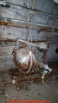
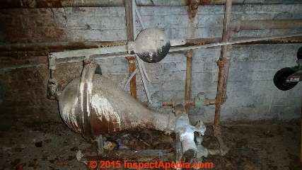
40. Above: Steam powered condensate return pump, not in service. - C.M.
This is one of two steam operated condensate return pumps stored in the tunnels - no longer in service but dating from the early steam installation when electrical power was not available to operate a condensate return pump system.
41. Above: Condensate entered the tilt pump at its small end and accumulated in the bulbous condensate reservoir. When the quantity of condensate was sufficient that its weight would tip the assembly down (the large end drops) enough to overcome the adjustable counterweight the assembly tips which opens a valve to permit steam to enter the assembly, blowing the condensate back to the steam boiler.
This is one of my favorite steam devices even though it's one that's no longer in use.
Early Electrical Power Distribution Cable from Beneath New York City Streets
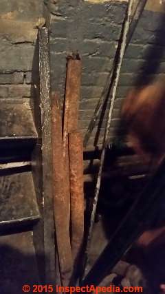
A collection of rusty "pipes" (below) leans on a wall in the Pratt Engine room. But it's a bit more interesting than rusty pipe. An early charter
42. Above: these are lengths of electrical cable described below.
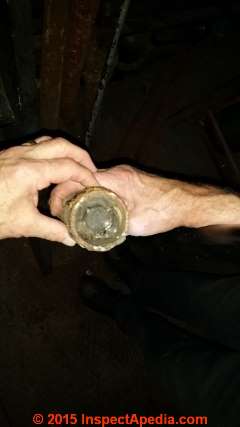
Below: a snippet (ok really a hacksawn chunk) of New York history: these are original Edison DC electrical power cables from beneath a New York City Street. Milster spotted these while looking into a utility trench where Con Ed was doing some other work.
He obtained sample segments of both the DC electrical system distribution cabling and the connecting joints that were used between these "wires" to permit lateral connections to buildings.
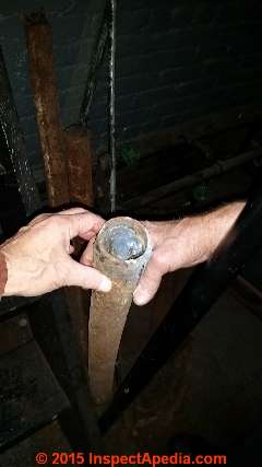
43. Above: We're looking at the cut-end of whatis most likely a section of original DCoriginal DC or continuous current distribution cabling salvaged from a NYC trench. The solid copper core is much thicker than my thumb.
It's Conrad's eye of an engineer that is turned towards history that enabled him to spot and salvage this interesting relic that otherwise would certainly have been buried in a landfill.
44. Above: The solid copper core was wrapped in rope to insulate it from the iron pipe and the space between that cable and the surrounding iron pipe was filled with a pitch-like substance. - C.M.
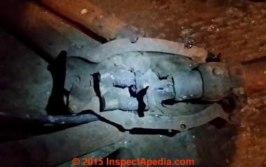
45. Above: Ends of 20-foot long pipes terminated in cast-iron boxes where they were connected with soldered jumpers. - C.M.
The electrical cable junction box that permitted both joining of the otherwise pipe-encased electrical power distribution cables and perhaps the tapping off to bring electrical power into nearby buildings.
More about these and other old electrical wiring materials can be read at OLD ELECTRICAL WIRING TYPES
Continuous Power Electrical Generators in the Pratt Institute Engine Room
46. Above: Electrical end of the turbine.
These are views and details of the original General Electric steam-driven electrical power generators in the Pratt Engine Room, photographed in 2015.
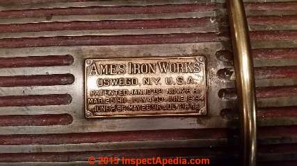
47. Above: This engine data tag identifies is fabricator: Ames Iron Works in Oswego NY.
48. Above: MG [motor generator] set used for DC to the elevators after enines shut down.
49. Above: DC electrical generators
50. Above: This DC electrical generator, steam powered since its original installation, was referred to by its manufacturer, the General Electric Company as a Continuous Current Generator.
This was Continuous Current Generator No. 21025, Spec. No. 7976, Type MP, Class 6-75-270, Form L, Amps 641, Speed 270, Volts No. Load 112, and Volts under Full Load 117. This generator was patented on 14 February 1888 by the General Electric Company with related patents on 14 October 1890 and 14 November 1893, 26 February 1895, and 5 May 1896.
51. Above: data plates from the G.E. DC electrical generators.
Mr. Milster's comments about DC electrical power at Pratt:
Regarding the use of DC electrical power: DC (direct current) was originally used for light and power in original campus buildings . No metering was involved except for meters in plant giving kwhrs for light and power use .
No cables ever got warm to the point of over load even toward the end when the load became too small for 2 engines . we some times ran the engines with the meter pointer almost at the end of the scale when trying to get by with one engine . Maximum plant load in its heyday ran 1500 - 2000 amps .
Daily use of engines stopped summer 1977 but engines were on standby for MGset [motor generator set] which supplied DC for elevators on the Pratt campus till about 10-12 years ago when elevators were modernised .
At the same time all plant asbestos was removed and it was discovered that switch board cables had asbestos sleeves on them for fire protection and so cables connecting engines to switchboard were removed. The steam-powered electrical power-producing engines can still run but they no longer produce any power .
Final comment: the correct phrase for DC was continuous current. [As readers will find in the citations at the end of this article - Ed.]
52. Above: detail of oil metering valve , no 1 boiler - C.M.
Pratt Institute Engine Room Machine Shop
52. Above:
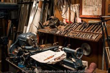
It should come as no surprise that the Pratt steam room needs its own machine shop nor that Conrad has used his mechanical engineering expertise to re-build and restore gauges, controls, parts, clocks, and of course his renowned steam whistles for decades. As he has demonstrated, old machinery, in the hands of a lover, is very stable, very reliable. The equipment we show in these photos and videos is the antithesis of a throw-away culture.
Above & immediately below: this photograph of the Conrad Milster in the Pratt Institute steam room machine shop and the machine shop detail provided just below were provided courtesy of NY photographer / director Dustin Cohen, producer of Conrad and the Steamplant.
Conrad is holding what I'm pretty sure is one of the piston rings used to re-build the steam operated condensate return pump shown earlier in this article.
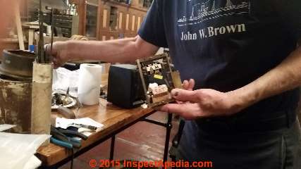
53. Below: Mr. Milster was showing me a clock re-build project that's underway.
Conrad Milster is the fourth Chief Engineer at the Pratt Institute's Engine Room in more than 125 years of operation.
54. Above: engraving showing original generating engines in background , belt drive corliss engine for first floor shops in foreground. - C.M.
At ground level near the entry to the Pratt Engine Room, aka steam room, you will find a collection of prints and photographs including the print below showing the Pratt Engine Room at its original installation. Pratt Institute has had reason to be proud of this installation for more than a century.
Post Script: Plea for a Pratt Institute Steam Museum
Above: this stunning photograph of the Conrad Milster leaving the Pratt Institute steam room is provided courtesy of NY photographer / director Dustin Cohen, producer of Conrad and the Steamplant.
Conrad was incredibly generous and unpretentious with me as he is with all visitors, taking considerable time explain to me what one finds in the Pratt Engine Room. I suppose Conrad in turn enjoyed someone who who knew what a steam condensate return pump is for, likes variable firing rate oil burners, and who worries about rebuilding the tubes in an antique steam boiler.
Mr. Milster, at 80 in 2015, is preparing to retire from the facility, maybe moving to Beacon N.Y. If Conrad agrees, I expect to make a return visit before that event in order to complete a more thorough and organized (by system) photo inventory of the Pratt Engine Room and to document the function, operation, age and history of each machine, pump, and control.
In Cohen's video (cited just below) we hear Conrad's thoughts expressed:
"When I leave, a lot of things are going to change.
Is anybody going to give a damn about keeping the engines in nice looking condition out there? Will any modern manager put up with incandescent lighting in here? Who going to take care of the cats when I'm gone? I sort of fear for the things which I cherish being threatened.
Conrad thinks that Pratt will scrap the whole facility when he's gone. I hope the institute will consider making it into a working steam museum. The Pratt Engine Room is not just beautiful, it is a unique facility: I doubt there is another anywhere that has had a lifetime of loving and expert restoration by such a talented and informed engineer.
References: history of the Pratt Institute Engine Room & Steam Plant
Early electrical power in New York City, DC or continuous current vs AC, Edison v Tesla.
- Cohen, Dustin, "Conrad and the Steamplant" [Video], retrieved 2015/12/10, original source: Website: https://vimeo.com/127713670
Mr. Cohen is a New York City-based photographer and director. I extend special thanks to Mr. Cohen for his generous permission to reproduce copies of his photographs and video stills of Conrad Milster and the Steam Plant.- Web page: http://www.dustincohen.com/STORIES/CONRAD-&-THE-STEAMPLANT/thumbs including both the video link above and Mr. Cohen's still photographs of the Pratt Engine Room and of Conrad Milster (and some cats).
- Website: www.dustincohen.com
- Email: dustin@cohen.net
- Conrad Milster, Chief Engineer, Pratt Institute, Email: cmilster@pratt.edu [NOTICE: Mr. Milster says he rarely checks email - Ed.]
- De Witt, B. "System of electrical distribution." U.S. Patent 484,549, issued October 18, 1892.
- Edison TA, inventor. Pyromagnetic generator. United States patent US 476,983. 1892 Jun 14.
- Hargadon, Andrew B., and Yellowlees Douglas. "When innovations meet institutions: Edison and the design of the electric light." Administrative science quarterly 46, no. 3 (2001): 476-501.
Abstract:
This paper considers the role of design, as the emergent arrangement of concrete details that embodies a new idea, in mediating between innovations and established institutional fields as entrepreneurs attempt to introduce change.
Analysis of Thomas Edison's system of electric lighting offers insights into how the grounded details of an innovation's design shape its acceptance and ultimate impact. The notion of robust design is introduced to explain how Edison's design strategy enabled his organization to gain acceptance for an innovation that would ultimately displace the existing institutions of the gas industry.
By examining the principles through which design allows entrepreneurs to exploit the established institutions while simultaneously retaining the flexibility to displace them, this analysis highlights the value of robust design strategies in innovation efforts, including the phonograph, the online service provider, and the digital video recorder. - Hunter, Rudolph M. "Method of and apparatus for the transmission of electrical energy." U.S. Patent 503,321, issued August 15, 1893.
- Kilgannon, Corey, "In an Old Steam Plant, Providing a Home for the Many Cats of Pratt", The New York Times, 24 May 2013, current source:
http://cityroom.blogs.nytimes.com/2013/05/24/in-an-old-steam-plant-providing-a-home-for-the-many-cats-of-pratt/?_r=0 - Marvin, Harry N. "Pulsating-current generator." U.S. Patent 479,951, issued August 2, 1892.
- Pope, Franklin Leonard. Evolution of the electric incandescent lamp. Boschen & Wefer, 1894.
- Pratt Institute, North Hall, 200 Willoughby Ave, Brooklyn, NY 11205, Tel: (718) 636-3886, Website: https://www.pratt.edu/
The "Pratt Institute is located in the Clinton Hill neighborhood of Brooklyn, New York, United States. The website author first visited the Pratt steam room in 2015. - Tesla, Nikola. "Nikola tesla." U.S. Patent 447,921, issued March 10, 1891.
- Tesla, Nikola. "Nikola tesla." U.S. Patent 454,622, issued June 23, 1891.
- Tesla, Nikola. "Electro-magnetic motor." U.S. Patent 381,968, issued May 1, 1888.
- Tesla, Nikola. "A new system of alternate current motors and transformers." AIEE Transactions 5 (1888): 305-327.
- von Slatt, Jake, "A Visit to the Pratt University Steam Plant", [web article], retrieved 2015/12/11, original source: http://steampunkworkshop.com/visit-pratt-university-steam-plant/
...
Reader Comments, Questions & Answers About The Article Above
Below you will find questions and answers previously posted on this page at its page bottom reader comment box.
Reader Q&A - also see RECOMMENDED ARTICLES & FAQs
Question: proper setting for a Honeywell PA-404-A 1099 Presstrol on a steam boiler
DOEs ANYONE KNOW THE PROPER SETTING FOR A HONEYWELL PA-404-A 1009 PRESTROL CONTROL FOR A WEIL-MCLANE STEAM BOILER - Rick 9/11/11
Reply:
Rick the exact pressure needed varies by installation but in a low pressure residential steam system the pressure range is usually between 0.2 and 0.4 psi.
Question: steam pipe configuration question at the boiler
what's the term they call the 2 steam pipes that form an H above a steam boiler. in other words the pipes from both sides of the burner connected together?THANKS,Walter - 9/25/11
Reply: steam pipe header
Walter: sorry we couldn't give an instant reply; sometimes the volume of reader questions is considerable and takes some time to get thorough.
I am guessing you are referring to the steam header or manifold piping that allows steam to enter more than one steam supply line or riser.
A second piping configuration that will be along side, not above, the boiler is the Hartford loop - a loop of piping sort of like an upside down trap that prevents water from siphoning out of the boiler should there be a leak in the condensate return line.
Question: steam boiler parts identification
Wow, what a great web site. I am trying to identify a vessel on the side of an old National steam boiler/furnace. It is about 12-18" tall, about 8" diameter and is attached to a manifold in the side that is about 12" off the floor. It is heavily rusted. The boiler is an old coal fired converted to oil. Can I send you photos? Thanks, Stephen strentsch@yahoo.com or strentsch 10/4/11
Reply:
sure Mr. Strentsch,
use the CONTACT link found at page top, left, or bottom to see our email and send along some sharp photos and we'll be glad to take a look
Question: My steam boiler seems to be taking more water than usual
I blow the system down regularly and then make up the water in the sight glass. However I seem to be using significantly more water then years past whereas I'd top the sight glass every couple of weeks in the past compared to every other day now. What do you think the problem is? - Tom C 10.27.11
Reply:
Tom C: a common reason for increased water consumption in a steam heating system is one or more radiator steam vents that are not closing properly. Check also for a leak in the condensate return line.
Question: I need to prepare for a steam boiler license and want book recommendations
I’m happy to have found this website. I’m getting back into heating and cooling and need to prepare for higher license. Question: Is there a DVD collection you recommended as an additional studying tool? I see that Harold J. Frost, Frederick M. Steingress, Daryl R. Walker’s collection is close to 600.00 which is very steep for my pocket. Would you happen to know of a website or cheap place I can buy such DVD or a CD? If not these guys than another author is ok. Thanks for the feedback. Kym 11/23/11
Reply:
Kym if you are looking specifically for information on steam heating I'd pick up any of Dan Holihan's books on steam heat. He's the best.
Question:
The HomeServ tech just left after installing a new auto water feeder, and the PSI gauge on my steam heater is off the chart, over 30 PSI. I shut it down and called HomeServ and they said leave it on and they'll come in the morning. How do I lower the PSI myself so I can leave it on tonight and my little kids (two with strep) don't freeze? Thanks! 2/22/2012
Reply:
Watch out: If the PSI gauge is showing abnormal pressure and the gauge itself is working properly the system is unsafe and should be shut down. Call someone else and fire that tech - from your description the system sounds unsafe
Question: water drips out of the air valve at the bottom of the tank
I HAVE AN OIL BURNER HOT WATER SYSTEM MY EXPANSION IS DRIPPING WATER OUT THE AIR VALVE STEM AT THE BOTTOM OF THE TANK SHOULD I REPAIR OR REPLACE - Mike S 10/12/12
Reply:
Mike, an air valve stem is replaceable, I would tr that first. Check also for abnormal system pressure ( an unsafe condition). But if the internal bladder of the tank has burst - another explanation for finding water at the air pressure adjustment valve, then most likely you need to replace the tank. You'll know this condition because the tank will become waterlogged, heavy, and ultimately the boiler TP valve will drip (another unsafe condition).
Question: radiator banging noise repair procedure
I have a one pipe steam system. My dining room radiator air vent was just replaced because the old one was leaking profusely (damaged my floors). The porch radiator air vent was also replaced because of too much steam condensation in the room, but now the open/close valve is leaking at the base. The radiator upstairs in middle bedroom is banging and clanking. The pipe that runs along the basement ceiling (finished basement) also bangs when the heat is coming on. My plumber cannot really give me an answer. Any suggestions would be appreciated. Thanks p Rita 11/21/12
Reply:
Rita,
If you search InspectApedia for
BANGING STEAM PIPES
you can read about the diagnosis & cure of this problem
About the leaking valve - unfortunately that means you need another service call.
Question: relief valve is leaking
cleaned on a vav [?] system is leaking close the cilanod [solenoid ? -Ed] valve need to be replaced
- Anon 11/23/12Reply:
See RELIEF VALVE LEAKS for procedures to diagnose and fix leaky TP relief valves.
Question: too-high steam pressure traced to a blocked sensor on steam pressure control
Pressure on gas steam boiler was rising far too high, so high that the pressure relief valve released twice when it hit 15 psi (as it was supposed to do). Good buddy who really knows his stuff checked everything from pressure valve to pressuretrol. Nothing . He then checked "pigtail" and found blockage .Problem solved!! - Ken 11/24/12
Reply:
Thanks for this note it may help other readers
Question: trouble controlling level of steam heat - can I close off the radiator
My building uses steam heaters. I have no control over the heat in my unit because the thermostat is controlled by my landlord/owner who lives above me. However I have a small 1 bedroom with two heating units so even with all of the windows open, it can still get very hot. Is it okay for me to completely close the "open/close" black knob valves on my units or will that cause problems for the whole system? My landlord had previously told me not to touch the valves... Emily 12/10/12
Reply:
Yes if the radiator control knob is not jammed or frozen you can try closing it partly or fully; radiator control knobs are intended to be a homeowner-resident-operator control. But if the knob is not easy to turn, don't force it as you might end up with a leak.
Question: hissing boiler
I have 2 yr. Boiler. It hisses like venting steam off and on loudly. Seems like when heat comes on venting starts until off. -Mr. Ed 12/28/12
Reply:
Steam boilers include steam valves that hiss; we need more details.
Question: leaky relief valve
I am having a pressure problem and it looks like one of my relief valve is leaking or letting the pressure out would this keep my boiler from running. It seems to be shutting off and I need to set the pressure all the time. is it as simple as changing the valve and resetting the Pressure? Rick 1/3/2013
Reply:
See RELIEF VALVE LEAKS for procedures to diagnose and fix leaky TP relief valves.
Question: 28 psi and water coming out of my return on my American Standard boiler
II have a pressure of 28 psi and water is coming out of my return how can i lower the water pressure from my steam American standard boiler - Ronald 1/13/2013
Reply: 28 psi on residential steam heat is very unusual, probably unsafe - shut the system off
Ronald,
Watch out: If your heater is a residential steam heating system it is operating at an abnormally high temperature and is unsafe. Turn the system off immediately and call your heating service company.
If your heater were a residential hot water heating boiler (hydronic heat) its pressure might be close to the upper end of normal operating pressure - and the leak at the valve could be due to a valve problem or to any of quite a few other causes. See RELIEF VALVE LEAKS for procedures to diagnose and fix leaky TP relief valves. See the links just below for information on how the steam heating system pressure is controlled and set.
Question: steam boiler won't get up to heat setting
(Mar 23, 2013) home able said:
Oil-fired steam boiler was functioning properly upto two weeks ago, now doesn't fully run to designated temperature on thermostat (digital). It will stop a degree or 2 short of desired setting even though thermostat says boiler is running. Why?
Reply:
Home able,
I'm not sure what's happening with your system. IN general the gauges are not lab grade precise. It's possible that your gauge or its sensor port are debris clogged. Try tapping gently on the gauge to see if the needle moves. Also watch the gauge to see its reading throughout the operating cycle.
Question: steam boiler keeps flooding - high water in the sight glass
(Apr 1, 2013) Luis said:
I have a gas bolier which continues to overflow. The sight glass floods even some pipes that run thogugh the floor ang o up the wall with a steam trap a gauges at the to of the pipes. I called a company but they have not been able to find the problem.
Reply:
Luis if the steam boiler keeps overflowing, or flooding, most likely the water feeder is out of order
OR
The condensate return pipes are partly clogged - delaying condensate return to the boiler; the boiler water level drops, makeup water is added, then when the system cools down and all the condensate returns, the boiler is flooded.
Question:
(june 19, 2014) anonymous said:
I have hot water baseboard system boiler in my crawlspace (.Basement) im thinking about replacing the boiler with a horizontal warm air furnace adams furnace. I keep getting freezeups and they are very difficult to repair. The furnace adams make is supposed to be 95 percent efficient. Plus the fact there are no pipes to freeze is the warm air furnace the way to go? Thanks paul
Reply:
Paul,
You're commenting about hot water and hot air heat on a steam heat article - so this may be a bit confusing to other readers, but in general, conversion to another heating method is fine if you can bear the expense; each heating type has its pros and cons so IMO there is not a single "right" answer. Keep in mind that when you change from steam heat or hot water heat to forced warm air heat, your costs are much greater than just the heater itself as you have to install a heat delivery system : air ducts and registers. That can be convenient in some building designs and quite costly in others.
Question: what would be the right pressuretrol settings on my steam boiler
(Oct 16, 2014) Antonio said:
I just installed a 299 MBH gas fired steam boiler and connected to an existing system serving the second floor of an office building, approx floor area is 2,600 sq ft.
Existing EDR calculated as approx 900 sq. ft. The boiler started up successfully yesterday and I have been testing it ever since. Everything seems to be working fine. My question is what would be the right pressuretrol settings: I am using 1 psi cut-in and 1 psi differential and everything seems all right, but I may be missing something, maybe the boiler could work more efficiently with a lower or higher cut in pressure.
(Dec 15, 2014) Kevin M said:
I have a gas-fired steam boiler that has worked flawlessly since its installation six years ago. Suddenly it is overfilling. I let out several extra gallons a day to reduce the level in the sight glass. Shoudl I replace the automatic feed? It is attached to the hot water heater, unlike previous installation I have had in othe rhouses where it is connected to the cold water line. I sit possible that excess pressure from the expansion in the hot water supply line is forcing water past the automatioc feed? What could cuase this condition?
Reply:
Kevin
Over-filling of a heating boiler is indeed usually a problem with the automatic water feeder, more rarely leaks into the boiler from a tankless coil.
Question: bothered by banging pipes
(Feb 15, 2015) Bevery Streeter said:
I live in a 16 unit apt complex. What make the heat clan and banging?
Reply:
See the banging pipe diagnostic and repair suggestions at BANGING HEATING PIPES RADIATORS
Question: steam boiler won't keep running
(Apr 9, 2015) george said:
steam boiler heater runs for about 15 minutes then it cuts out
Reply:
George I'm stuck on this one with no onsite data; could be related to heating of components, clogging of a filter, I dunno. It's time for an onsite heating service tech.
DO NOT keep pushing a re-set button. That's unsafe.
...
Continue reading at STEAM HEATING SYSTEMS & CONTROLS - topic home, or select a topic from the closely-related articles below, or see the complete ARTICLE INDEX.
Or see these
Recommended Articles
- AGE of a BUILDING, HOW to DETERMINE - home
- STEAM HEAT RADIATOR REPAIR - diagnose & repair
- STEAM BATH / SHOWER GENERATOR INSTALLATION
- STEAM VENT TYPES, SELECTION
- STEAM VENTS, 2-PIPE SYSTEMS
Suggested citation for this web page
STEAM BOILERS GENERATORS CONTROLS, PRATT at InspectApedia.com - online encyclopedia of building & environmental inspection, testing, diagnosis, repair, & problem prevention advice.
Or see this
INDEX to RELATED ARTICLES: ARTICLE INDEX to STEAM BOILERS
Or use the SEARCH BOX found below to Ask a Question or Search InspectApedia
Ask a Question or Search InspectApedia
Try the search box just below, or if you prefer, post a question or comment in the Comments box below and we will respond promptly.
Search the InspectApedia website
Note: appearance of your Comment below may be delayed: if your comment contains an image, photograph, web link, or text that looks to the software as if it might be a web link, your posting will appear after it has been approved by a moderator. Apologies for the delay.
Only one image can be added per comment but you can post as many comments, and therefore images, as you like.
You will not receive a notification when a response to your question has been posted.
Please bookmark this page to make it easy for you to check back for our response.
IF above you see "Comment Form is loading comments..." then COMMENT BOX - countable.ca / bawkbox.com IS NOT WORKING.
In any case you are welcome to send an email directly to us at InspectApedia.com at editor@inspectApedia.com
We'll reply to you directly. Please help us help you by noting, in your email, the URL of the InspectApedia page where you wanted to comment.
Citations & References
In addition to any citations in the article above, a full list is available on request.
- Gordon, John Steele, "A Steam-Powered Proof of Concept" [Essay], Barrons, 28 March 2016 p. 29
- The Steam Book, 1984, Training and Education Department, Fluid Handling Division, ITT [probably out of print, possibly available from several home inspection supply companies] Fuel Oil and Oil Heat Magazine, October 1990, offers an update, (see next item in this list). ITT Fluid Technology, 1133 Westchester Avenue
White Plains, NY 10604, tel +1 914 304 1700 fax +1 914 696 2950 www.ittfluidbusiness.com - Principles of Steam Heating, $13.25 includes postage. Fuel oil & Oil Heat Magazine, 389 Passaic Ave., Fairfield, NJ 07004.
- The Lost Art of Steam Heating, Dan Holohan, 516-579-3046 FAX
- Principles of Steam Heating, Dan Holohan, technical editor of Fuel Oil and Oil Heat magazine, 389 Passaic Ave., Fairfield, NJ 07004 ($12.+1.25 postage/handling).
- The Heat Efficiency of Steam Boilers, Bryan Donkin
- Steam Boiler Operation, Principles & Practice, James J. Jackson
- The Steam Book, 1984, Training and Education Department, Fluid Handling Division, ITT [probably out of print, possibly available from several home inspection supply companies] Fuel Oil and Oil Heat Magazine, October 1990, offers an update,
- Principles of Steam Heating, $13.25 includes postage. Fuel oil & Oil Heat Magazine, 389 Passaic Ave., Fairfield, NJ 07004.
- The Lost Art of Steam Heating, Dan Holohan, 516-579-3046 FAX
- Principles of Steam Heating, Dan Holohan, technical editor of Fuel Oil and Oil Heat magazine, 389 Passaic Ave., Fairfield, NJ 07004 ($12.+1.25 postage/handling).
- "Residential Steam Heating Systems", Instructional Technologies Institute, Inc., 145 "D" Grassy Plain St., Bethel, CT 06801 800/227-1663 [home inspection training material] 1987
- Boilers, Boiler Conversions, James E. Brumbaugh, ISBN 0-672-23389-4 (v. 1) Volume II, Oil, Gas, and Coal Burners, Controls, Ducts, Piping, Valves, James E. Brumbaugh, ISBN 0-672-23390-7 (v. 2) Volume III, Radiant Heating, Water Heaters, Ventilation, Air Conditioning, Heat Pumps, Air Cleaners, James E. Brumbaugh, ISBN 0-672-23383-5 (v. 3) or ISBN 0-672-23380-0 (set) Special Sales Director, Macmillan Publishing Co., 866 Third Ave., New York, NY 10022. Macmillan Publishing Co., NY
- In addition to citations & references found in this article, see the research citations given at the end of the related articles found at our suggested
CONTINUE READING or RECOMMENDED ARTICLES.
- Carson, Dunlop & Associates Ltd., 120 Carlton Street Suite 407, Toronto ON M5A 4K2. Tel: (416) 964-9415 1-800-268-7070 Email: info@carsondunlop.com. Alan Carson is a past president of ASHI, the American Society of Home Inspectors.
Thanks to Alan Carson and Bob Dunlop, for permission for InspectAPedia to use text excerpts from The HOME REFERENCE BOOK - the Encyclopedia of Homes and to use illustrations from The ILLUSTRATED HOME .
Carson Dunlop Associates provides extensive home inspection education and report writing material. In gratitude we provide links to tsome Carson Dunlop Associates products and services.


