 Master Electric Company & Master Electric Motors
Photos & History of Master Electric Co. & Reliance Electric electric motors
How to Change Rotation Direction of a Master Electric Motor
Types of Motors & their Applications (e.g. Explosion-proof)
- POST a QUESTION or COMMENT about vintage Master Electric Co. electric motors
Information about older electric motors produced by Master Electric Company, Master Electric Co. Motors & Reliance Electric Company.
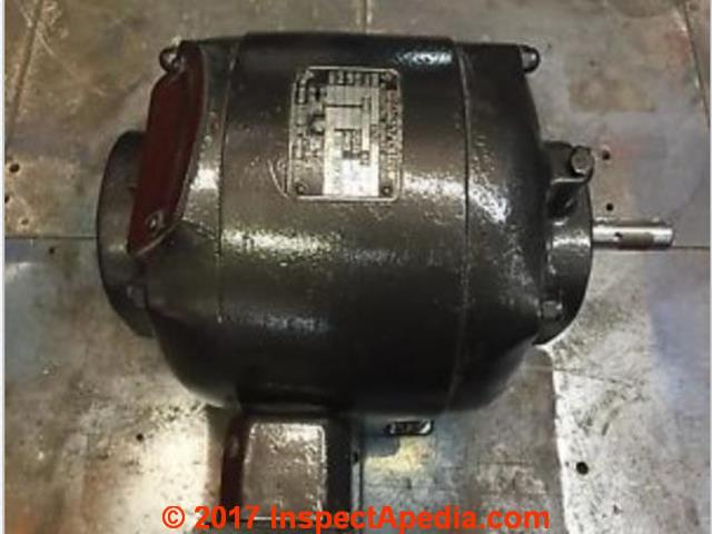
Page top photo: a 1963 vintage Master Electric Company motor.
InspectAPedia tolerates no conflicts of interest. We have no relationship with advertisers, products, or services discussed at this website.
- Daniel Friedman, Publisher/Editor/Author - See WHO ARE WE?
Master Electric Comnpany's Electric Motors
Here we illustrate several antique electric motors produced by the Master Electric Company, Master Alternating Current Motors, and similar products, giving company history.
We discuss when it's possible to re-wire these older electric motors to change their direction of rotation and we identify some of these electric motors as dual voltage repulsion induction motors that are not electrically reversible.
Article Contents
- HISTORY of MASTER ELECTRIC COMPANY
- REVERSE DIRECTION of an older MASTER ELECTRIC MOTOR
- MASTER GEARHEAD ELECTRIC MOTOR RESTORATION
- WIRING GUIDES for ANTIQUE ELECTRIC MOTORS
This article series describes A/C electrical motor troubleshooting: we provide an electric motor diagnostic table, a troubleshooting guide that helps diagnose and repair most electric motor problems for motors found on equipment in buildings such as air conditioners, furnace or air handler blower fans, oil burner motors, well pumps, and condensate return pumps.
...
History of Master Electric Co. Motors
Fatal Shock Hazard Warning: Inspecting electrical components and systems risks death by electrocution as well as serious burns or other injuries to the inspector or to others. Do not attempt these tasks unless you are properly trained and equipped.
Below: Older 1/2hp 1725 / 1425 RPM 3-phase electric motor and data tag from Master Alternating Current Motors, Master AC Motor Style 23721 7E
Also see more about data tags at ELECTRIC MOTOR DATA TAG
You will find electric motors from this company labeled as
Master Alternating Current, Mater Electric Co., Dayton Ohio USA
and also as
Reliance Electric Duty Master A-C Motor, Mfd. by Reliance Electric Industrial Co., Cleveland OH
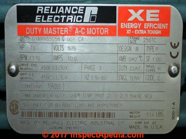 According to Vintage Machinery
The Master Electric Company was founded in 1920 and headquartered in Dayton, Ohio by Everett Larsh.
The company built electric motors, electric gear-motors, motor controls and motor brakes. They supplied private industry as well as the U.S. government.
In 1958 the company merged with Reliance Electric Company Reliance Electric Company of Cleveland, Ohio. Master's headquarters and plant in Dayton were closed in 1961 and moved to Columbus, Indiana.
Reliance bought ... Master [Electric AC Motors] in 1963 and [the Master Electric Company] ceased to exist.
... In 1982, Reliance moved its headquarters to Greenville, South Carolina... [and] was purchased by Rockwell International in December 1994, ... acquired in turn by the Baldor Electric Company 2007. - retrieved 2017/10/14, original source: vintagemachinery.org/ mfgindex/detail.aspx?id=3320
[Use the page top or bottom CONTACT link to send me photos of the motor and its data tag and I can comment further].
Readfer Question: Very Old Masters Electric Motor: Can I change run direction?
I have a very old Masters AC single phase 3hp motor that will run on 115v or 230v each hooked up the same way.
The motor runs clockwise and there is no indication on the tag if it can run CCW
The is only 4 wires coming out of the motor Black, Gray, Yellow, Red.
Yellow and Red are tied together for both 115v and 230v. while Black and Gray are hooked up to the power source along with a Green wire that is secured to a screw and does not come out from the inside of the motor.
Question is Can I swap either black or gray with either yellow or red to have the motor run CCW?
- Master alternating current motor
- Serial CX 205
- Style 252876
- Type RA
- RPM 1725
- Code C
- Frame 213
- HP 3
This is on the tag and I can't seem to find any information about this motor Thanks in advance. - On 2017-10-14 by Victor
Comment by Motor Expert CLHII: Victor's motor is a dual voltage repulsion induction motor that is NOT electrically reversible.
...
How to reverse direction of a Master Electric 115V / 230V electric motor
How To Reverse direction of a Master Electric 115V / 230V electric motor?
An electric motor will not normally run on either 115V or 230V "hooked up the same way" - so we are missing something here. I suspect you have an older motor that achieves 230V operation by wiring two individual 115V windings in series or in parallel to swap between.
Responding to reader Victor who asked how to re-wire this motor, we noted that this was probably from the Master Electric Co., in Dayton OH and would have been made before 1963.
Our illustrations of Master Electric Motors, Master Electric Motor Data Tags, and Reliance Electric Duty Master A-C Motor data tags shown
at MASTER ELECTRIC COMPANY MOTORS may be for different motor models than Victor's but they will provide examples for other readers.
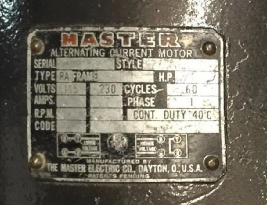
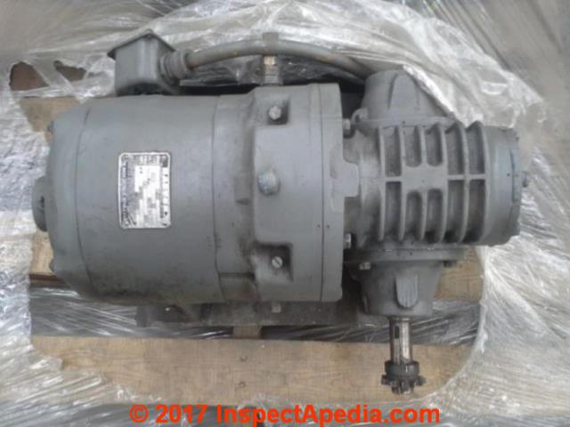
Shown above: a Master Electric Company (Dayton OH USA) electric motor ca 1960. This motor can be wired to run on 115VAC or 130 VAC single phase current, as you can just make out on its data tag given below.
Shown below: the data tag for this motor.
Is the Run Direction Reversible on this Electric Motor?
Here's the first thing to check: how many wires are coming off of the motor windings?
4 wires off of the windings means you can probably swap motor direction.
3 wires off of the windings means you cannot swap motor direction since 1 of those 3 is feeding both start and run windings.
Modern electric motors with more-current data tags will tell you right on the data tag that the motor run direction is reversible or not.
For example a non-reversible motor data tag might include this text: MOTOR IS NON-REVERSIBLE, CCW ROTATION SHAFT END.
For a motor that IS reversible a modern tag will usually give specific directions for reversing its direction, (usually swapping red and black wires) such as these examples (Warning: your motor will probably be different)
- AO Smith oil burner motor:
115V CCW Rotation: White-to-T1, Black to T2, Blue to T3, Red to T4, for CW rotation swap Red & Black,
for 230V Blue to T5, White to T3. [Notice thus that this motor is NOT going to run on 115V or 230V "hooked up the same way" - Craftsman power saw motor:
Swap RED & GREEN leads in the motor terminal box - On many reversible run direction electric motors,
possibly including yours, reversing the pair of [ hot+ neutral (115V) or red & black (230V] wires running to the motor windings will reverse its direction.
Separate start/run windings on electric motors
But on a 3hp motor it's probably not quite that simple. Your motor may have both a start winding and a separate "run" winding.
The winding with the smaller gauge or "thinner" wire will be the Start winding and that winding will be electrically in series with the start or S terminal on the motor's start/run capacitor or will be connected to a separate starting capacitor on motors that use two separate caps.
How to Identify the Start & Run Windings on an Electric Motor
You can also identify the start winding and run winding wires by measuring the resistance of that circuit.
The start winding will always have a much higher resistance (typically about 6 Ohms on small motors, or about 3x the run winding) than the run winding (typically about 1.5 Ohms on small motors) when measured using a VOM or DMM in the OHMS or Resistance setting.
Keep in mind that you cannot properly measure a coil winding resistance unless the wire ends are disconnected from the rest of the motor wiring.
On that motor type a centrifugal switch opens or turns "off" the start winding current once the motor is up to speed.
I would prefer not to try swapping the direction of a motor using a start winding before you find the actual wiring diagram (or figure it out) for the specific motor. But generally what you'd do is swap directions of the wires bringing current to the start winding.
While I have not (yet) found the exact wiring diagram for your motor,
here INSTALLATION, OPERATION AND MAINTENANCE OF RELIANCE® STANDARD INDUSTRIAL AC INDUCTION MOTORS - PDF is a book of wiring diagrams for the same series of motors when produced later under Baldor - as I'll explain in a historical note below.
...
Restoration & Use of a Vintage Master Gearhead Electric Motor
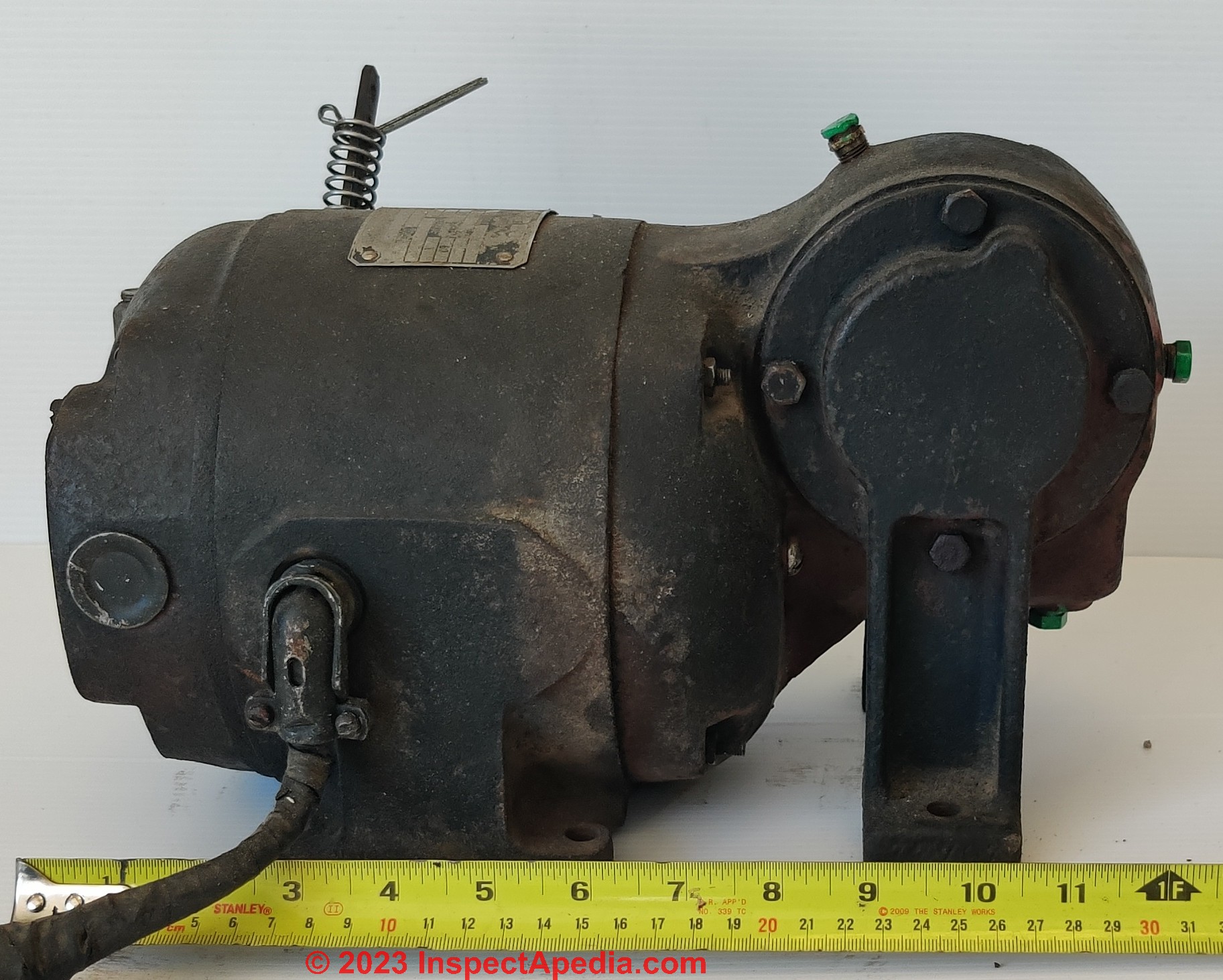
I have read on your site a very interesting thread about electric motor rotation, and amongst the responses was mention of and a picture of an old Master electric motor.
I have one of those in my hands, a Master Tearhead Motor, and I'm looking for maintenance and general usage information.
It is of unknown age and source; it is mounted with a 30:1 reduction box, which I have yet to open, but spins freely.
It has a lever outside, which allows to change its rotation direction at startup. Once spinning, moving the lever does nothing.
I'd like to know how best to care for this unit; What kind of electric motor is it? I'm reading it could be a Repulsion-start induction-run motor. What tests should be run to check the health of such motor? What lubricant and how much should be used in the gearbox?
Can the output shaft be positioned in all directions (the casting is made as to position the output shaft horizontally ; can it be run vertically?)
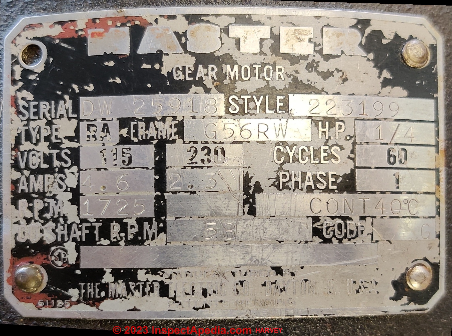
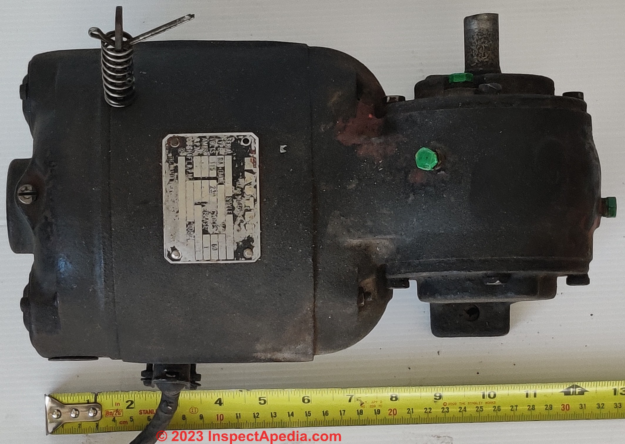
The nameplate says it's a style 233199, with a 1/4hp 1725 rpm motor with a shaft speed of 58 rpm.
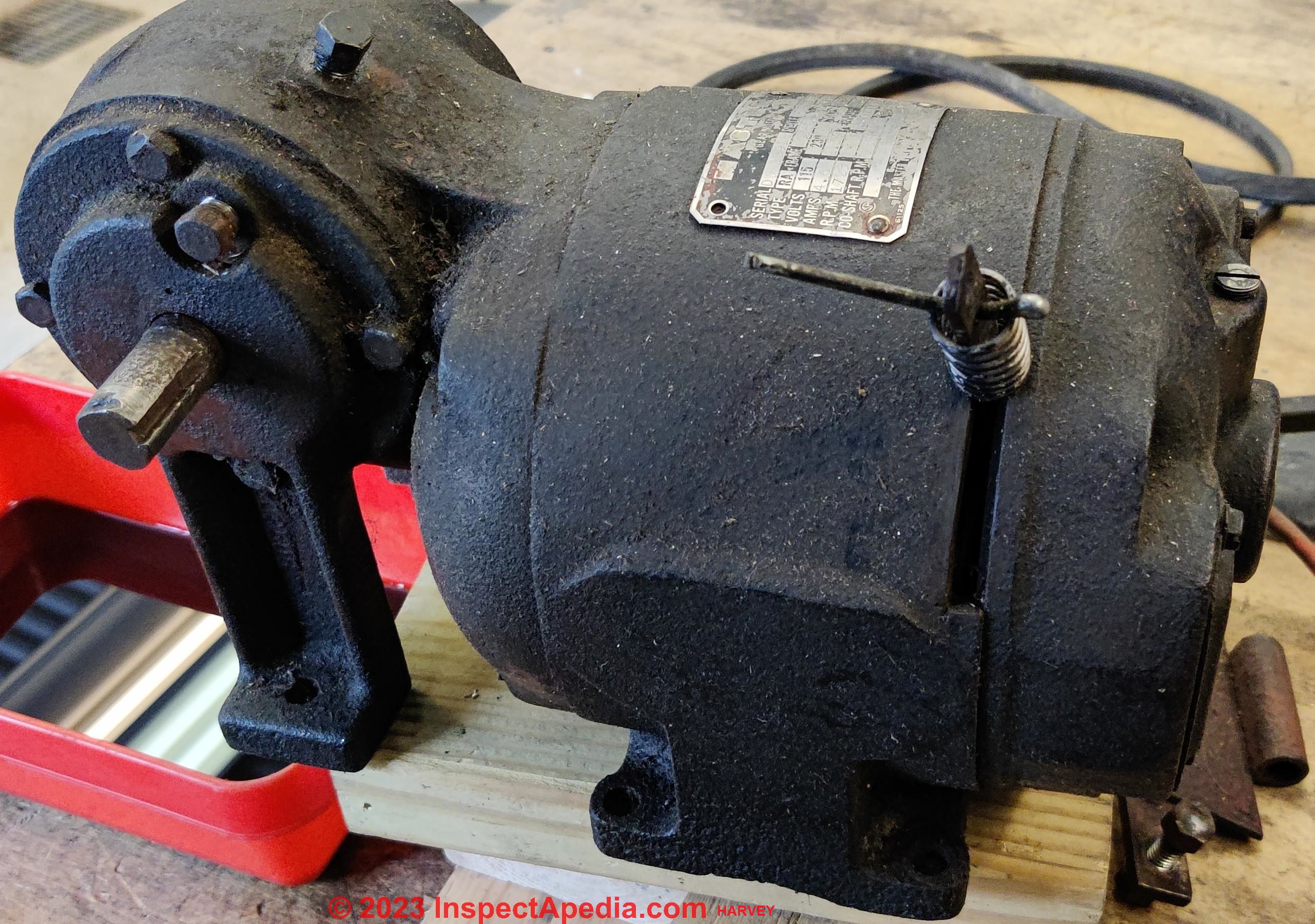
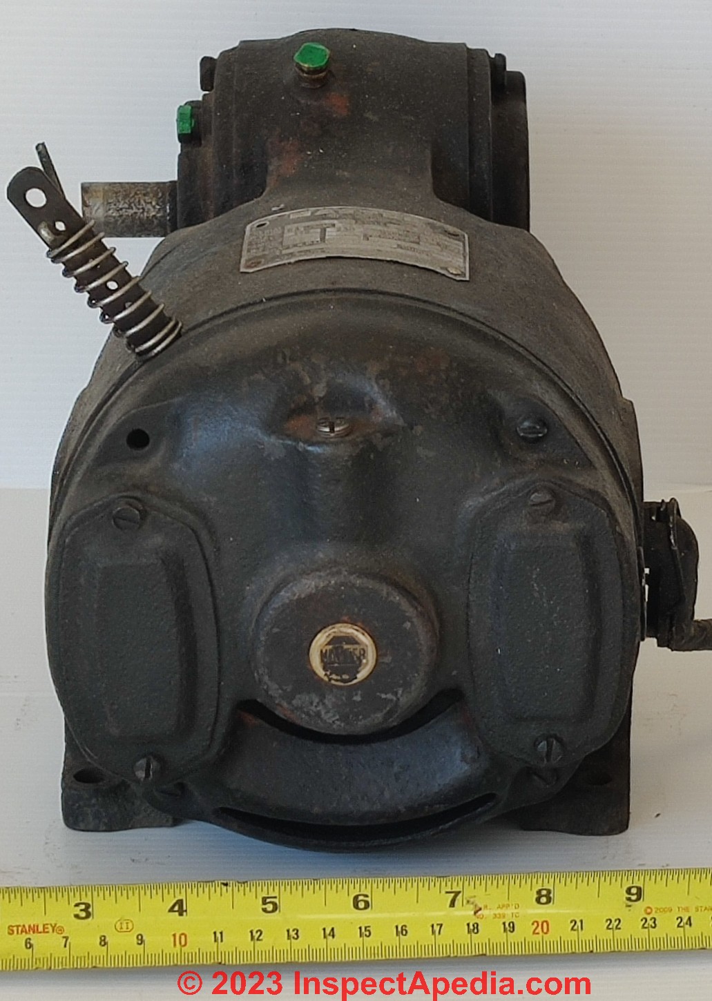
I am attaching a picture of the motor nameplate and the unit. Thanks in advance, Simon-Pierre Harvey by private email Apr 12, 2023
Moderator Reply: Notes on this antique Master Electric Co. Motor & Gear Drive
Thank you again for the wonderful photos of your vintage Master Electric Gear Motor - right-angle drive, and for the questions.
In addition to our own photos and notes on the History of Master Electric Motors (now promoted to its very on page found here), I did some easy additional research for both the Master Electric Co., Dayton OH, and also for that interesting right-angle driven gear and shaft on your motor.,
About what kind of motor it is and how it was designed to start and run, I don't know enough to tell that simply by looking at the motor's exterior. That manual motor rotation direction control is charming; on dis-assembly of the motor for maintenance we'll be grateful to see photos of its operation, presumably swapping a couple of electrical connections as we discuss
at ELECTRIC MOTOR RUN DIRECTION.
The serial number starting with DW and the type RA and the style number almost certainly will be decoded in an antique motor catalog if we can find one for these motors.
About running the shaft vertically, I don't know, but look at the existing hardware. It's quite plain that the gear and motor were intended to be run in the position of your photo - since there is a supporting foot with bolt-hole below the gear box.
Depending on gear box design and lubricant, there's often a ventilation opening that might leak lubricant if you flipped the motor over to try to run the shaft pointing up or down.
In addition to inspection of condition of the motor's electrical components, windings, internal wires, any controls, you'd of course also disassemble and inspect the motor shaft bearings at both ends.
Those may be salvageable - or not.
For gearbox lubricant, I'd look at the right-angle gear drive example PDF I give immediately below.
For motor lubricants,
see ELECTRIC MOTOR LUBRICATION
A motor restorer would typically tear the whole motor down, test the windings for continuity IF the windings looked usable - too often on a very old motor the wire insulation may be deteriorated enough that trying to power it up shorts out immediately.
Watch out: I would not even consider powering up something like that without considerable inspection and probably repair and cleaning, maybe even re-winding. The risk is that if you simply plug it in an internal short can burn up components, converting a restorable vintage electric motor to a melted and dangerous pile of slag.
You'll find this
- COPELAND ELECTRICAL HANDBOOK [PDF] a helpful reference.
Interesting, aside from the electric motor itself, probably dating from the 1950s or earlier, the problem of driving a right-angle gear has been widely addressed including by this nice coincidence
d1odbfykel3oe2.cloudfront.net/wp-content/themes/reverie-master/images/pdf/manuals/E3614-XL-RA-12-28.pdf
that describes
- MASTER XL RIGHT-ANGLE GEAR MOTORS & C-FACE REDUCERS SERVICE & REPAIR MANUAL [PDF] (2010) Master Power Transmission, 3300 Tenth St., Columbus IN 47201 USA, Web: www.master-pt.com - this manual is just gears - no motor. - retrieved 2023/04/18, original source: d1odbfykel3oe2.cloudfront.net/wp-content/themes/reverie-master/images/pdf/manuals/E3614-XL-RA-12-28.pdf
also see
- INSTALLATION, OPERATION AND MAINTENANCE OF RELIANCE® STANDARD INDUSTRIAL AC INDUCTION MOTORS - PDF is a book of wiring diagrams for the same series of motors when produced later under Baldor - as I'll explain in a historical note below.
For people interested in vintage machinery, Scott Adamietz at vintagemachinery.org has provided a tiny history at this page
vintagemachinery.org/mfgindex/detail.aspx?id=3320&tab=0#:~:text=The%20Master%20Electric%20Company%20was,merged%20with%20Reliance%20Electric%20Co.
Quoting, that entry adds a few details to our own history of the Master Electric Company above on this page.
The Master Electric Company was founded in 1920 and headquartered in Dayton, Ohio by Everett Larsh. The company built electric motors, electric gear-motors, motor controls and motor brakes. They supplied private industry as well as the U.S. government.
In 1958 the company merged with Reliance Electric Co. of Cleveland, Ohio. Master's headquarters and plant in Dayton were closed in 1961 and moved to Columbus, Indiana.
In 1967, Reliance purchased the Dodge Manufacturing Company of Indiana, a manufacturer of power transmission systems. The Columbus plant remained open, but a new plant was opened in Madison, Indiana and renamed Master Gearing.
---
You might want to contribute photos of your own antique Master Electric Company electric motor to the vintage machinery people at vintagemachinery.org - a website for people who enjoy using and/or restoring vintage machinery.
And you might get some help from those experts in restoring the antique motor in your photos.
Comment by Motor Expert CLHII: Simon's motor is a dual voltage repulsion induction motor that is NOT electrically reversible.
Reader Follow-up: This Master Electric Co. motor design permits pointing the driven shaft in any direction!
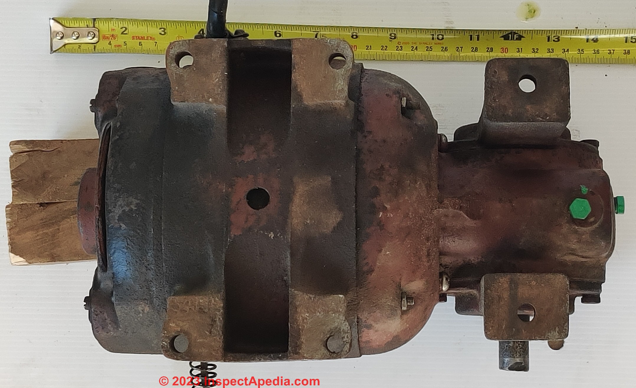
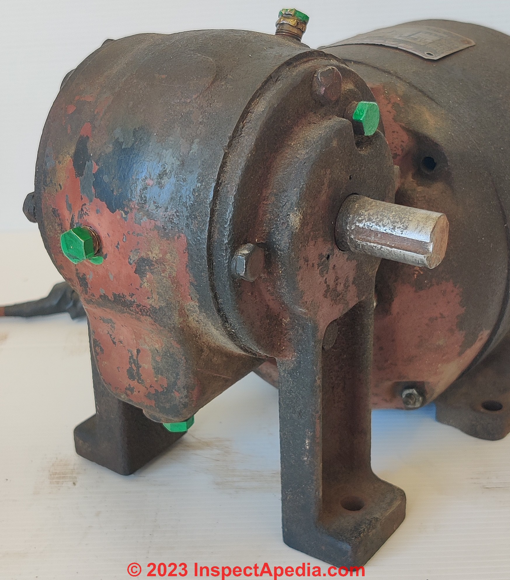
I've also figured how to use this unit with the shaft pointing in any direction; there is 4 different lubrication access holes in the gearbox, 3 with standard taper plugs and one is a brass 2-part vented plug.
Depending on the shaft direction, the upward facing hole receives the brass plug, the lowest one becomes the drain, and one more will be laying horizontally just below centerline, in a manner as to act as an oil level-indicator, which you plug back once oil stops pouring during fill-up.
I'll share those with the fine people of VintageMachinery as well. - SP Harvey 2023/-4/21
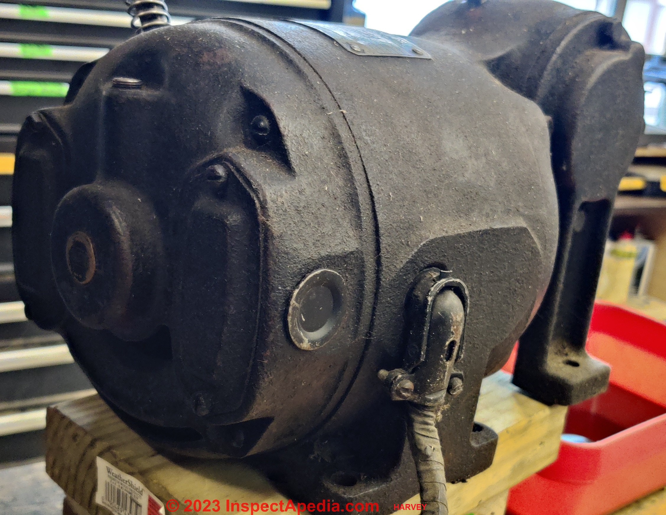
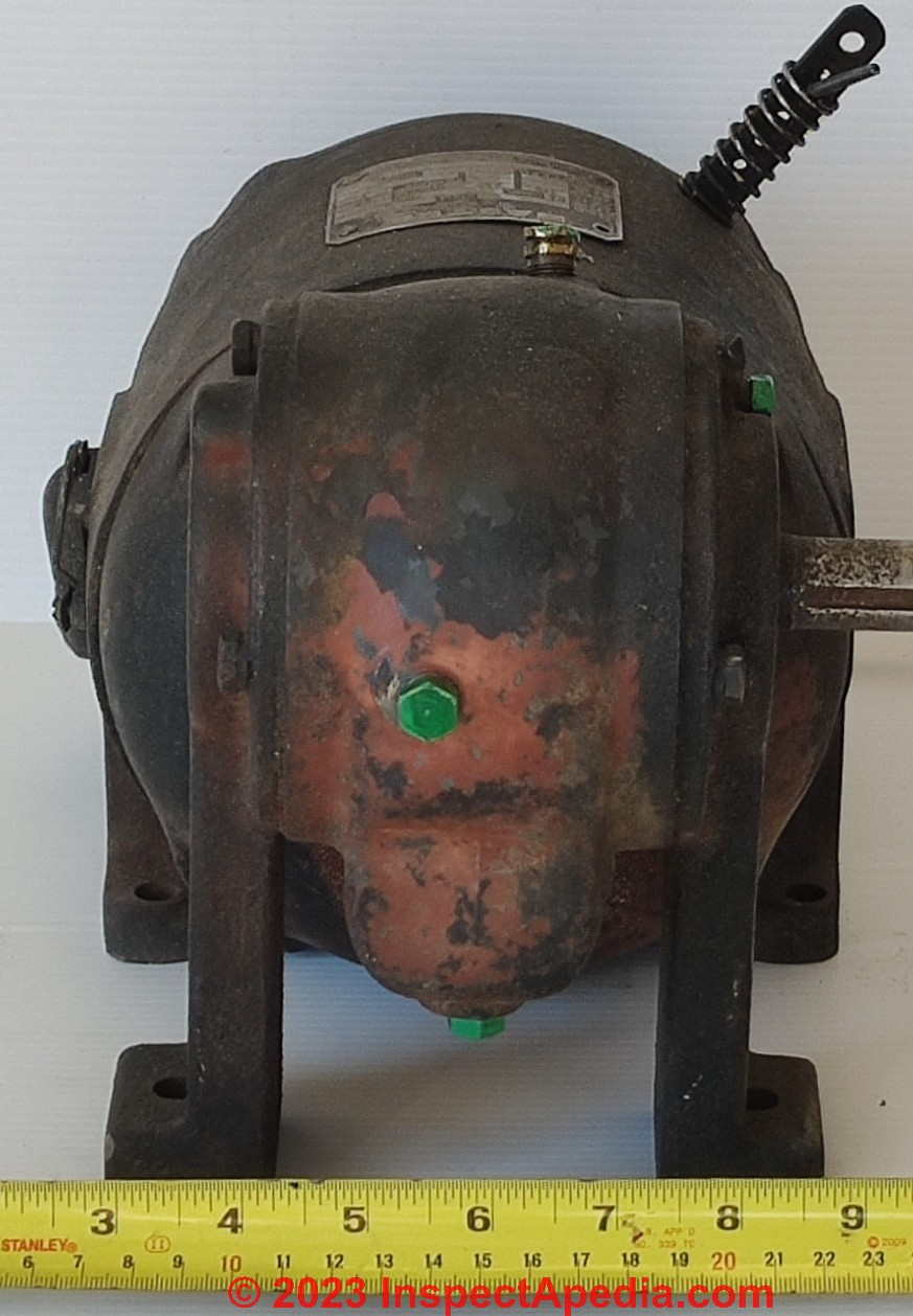
Here [Above and Below - Ed] are some better pictures of the Master Gearhead motor.
I've painted in green the four gearbox plugs; it's easier to see how they are distributed to that the motor can be mounted in any direction.
The output shaft is 0.750" (3/4").
The tall lever that has a spring and cotter pin controls the motor rotation direction; start the motor with the lever up, and it spins clockwise.
Start the motor with it down and it spins counterclockwise.
Moving the lever while the motor is spinning does nothing.
Attempting to start the motor with the lever not quite all the way up or down results in just buzzing, like the motor is stalled; from some reading I think this means this would be a repulsion-start induction-run motor. - SPH, May 14, 2023
...
Antique Electric Motor Wiring Guides
- COPELAND ELECTRICAL HANDBOOK [PDF] a helpful reference.
- INSTALLATION, OPERATION AND MAINTENANCE OF RELIANCE® STANDARD INDUSTRIAL AC INDUCTION MOTORS - PDF is a book of wiring diagrams for the same series of motors when produced later under Baldor
- MASTER XL RIGHT-ANGLE GEAR MOTORS & C-FACE REDUCERS SERVICE & REPAIR MANUAL [PDF] (2010) Master Power Transmission, 3300 Tenth St., Columbus IN 47201 USA, Web: www.master-pt.com - this manual is just gears - no motor. - retrieved 2023/04/18, original source: d1odbfykel3oe2.cloudfront.net/wp-content/themes/reverie-master/images/pdf/manuals/E3614-XL-RA-12-28.pdf
- ELECTRIC MOTOR WIRING DIAGRAMS & GUIDES [Web page] - lists more electric motor wiring guides and diagrams.
...
Reader Comments, Questions & Answers About The Article Above
Below you will find questions and answers previously posted on this page at its page bottom reader comment box.
Reader Q&A - also see RECOMMENDED ARTICLES & FAQs
On 2023-10-15 by CLHII - Summary of Types & Properties of Older Electric Motors
Both Victors and Simons motors are dual voltage repulsion induction motors that are NOT electrically reversible.
Victors motor is wired for 230V. It will start and run on 115V but will have no power. For 115V usage the black and yellow wires would be connected to line and the gray and red would be connected to neutral. The red and yellow are only connected together for 230V usage and the black is connected to one side of the line and the gray is connected to the other side of the line.
These motors have two parallel windings each designed for 115V and are connected in parallel for 115V use and in series for 230V use.
Other brands like Westinghouse had four wires coming out of the motor which were all the same color. These usually had a number tag attached to each wire or a number stamped on each wire for identification.
Usually 1, 2, 3, and 4 were used. 115V was line to 1 and 3, neutral to 2 and 4. 230V was line to 1, 2 and 3 connected together, and 4 connected to the other line. These motors are normally reversed by shifting the position of the brush plate.
Many have a locking screw that holds the plate in one position that results in CW rotation and loosening the screw and shifting the plate to the opposite position will result in CCW rotation.
Simons motor appears to be a garage door motor from the remote brush plate lever which would be shifted at the end of each operation of the door by a linkage attached or activated to a stop on the chain that moves the door. This would result in the motor running the opposite direction the next time it is turned and moving the door in the opposite direction.
There were electrically reversible repulsion motors but these were only used on conveyors and hoisting equipment. They would have four more leads coming out of the motor from the brush plate and switched by a heavy duty reversing contactor.
Almost any time these motors fail to start is due to worn brushes. They start as repulsion and when up to speed a shorting ring shorts out the bars of the commutator and they run as an induction motor.
Some motors also have a brush lifting mechanism to reduce brush wear while running in the induction phase, this and the shorting ring are activated by centrifugal weights that are usually not readily apparent when looking through the motor ventilation holes. Split phase motor have about 1.5 times the running torque when starting.
Capacitor start motors about 3 times, and repulsion motors have 4 times the running torque when starting.
Repulsion motors also can endure long starting cycles as they are operating as a series wound motor like a starter and normally are under full load when started.
Over 3 second starts will normally smoke split phase and capacitor motors (with the capacitor usually exploding) but repulsion motors can easily withstand 15 second starts or more.
Reply by InspectApedia Publisher (mod)
@CLHII,
Thank you those are very helpful electric motor details to add to this article series. I've included your comments at appropriate spots in the article above on this page.If you have any recommended references or manuals or citations that we could include that would also be great.
And if this is your area of expertise and you want to be cited as a professional simply use the page topper bottom contact link to send me an email. Thanks again.
On 2023-06-04 by Steve T I- s this Master Explosion Proof Electric Motor Worth Anything but Scrap?
Is this motor worth anything beyond scrap? Mint condition.
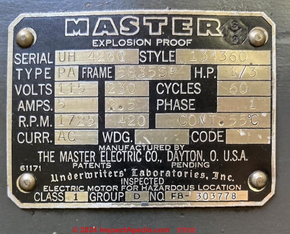
It Has an explosion proof armature attached if that proves important.
Reply by InspectApedia Publisher (mod)
@Steve T,
If the motor is working and in perfect condition it has some value and you might try selling it at an auction website considering that a new 1/3 horsepower utility motor cost between $100 and $150.Comment by CLHII - Data tag says this was probably a gas pump motor
@Steve T, From the size and specs it's probably an old gas pump motor.
Explosion proof and 1/3hp is normal for them. Does it also have a switch attached to it?
They were linked to the lever you raised after lifting the nozzle from the holder and would turn on the motor. - On 2023-10-15 by CLHII
On 2023-05-10 by Wittman Wharf Seafood - Need wiring instructions for a 230V Master Gearhead Motor - 4 white wires
How do you wire a 230 volt only for a Master Gearhead motor that is showing only 4 White wires out of the motor case?
Reply by InspectApedia Publisher (mod)
@Wittman Wharf Seafood,
Great question.
I wouldn't attempt to wire a motor with four wires of identical color without first determining what each wire is for.That might be done by inspecting the motor and following the wires to see where they go and if that's not sufficient then one would have to do some electrical tests using a VOM or DMM.
For example it's easy to identify which wires are connected to the start winding vs. the run winding simply by comparing the electrical resistance across wire pairs.
If your motor has a data tag on it you should be able to get additional information about it and perhaps find a wiring diagram but even then you can't connect your wires until you've identified them.See details of how to do this
...
Continue reading at ELECTRIC MOTOR DIAGNOSTIC GUIDE - home, or select a topic from the closely-related articles below, or see the complete ARTICLE INDEX.
Or see these
Recommended Articles
- AMPS MEASUREMENT METHODS
- ELECTRIC MOTOR DIAGNOSTIC GUIDE - home
- A/C ELECTRIC MOTOR COMPONENTS
- ELECTRIC MOTOR DATA TAG
- ELECTRIC MOTOR HORSEPOWER & CIRCUIT WIRE SIZE
- ELECTRIC MOTOR LUBRICATION
- ELECTRIC MOTOR NOISE DIAGNOSIS
- ELECTRIC MOTOR OVERHEATS
- ELECTRIC MOTOR RUN DIRECTION
- ELECTRIC MOTOR WON'T START / RUN
- ELECTRIC MOTOR TESTS
- ELECTRIC MOTOR WIRING DIAGRAMS & GUIDES
- HARD STARTING ELECTRIC MOTOR CAUSES
- DMM DIGITAL MULTIMETER HOW TO USE
Suggested citation for this web page
MASTER ELECTRIC COMPANY MOTORS at InspectApedia.com - online encyclopedia of building & environmental inspection, testing, diagnosis, repair, & problem prevention advice.
Or see this
INDEX to RELATED ARTICLES: ARTICLE INDEX to ELECTRICAL INSPECTION & TESTING
Or use the SEARCH BOX found below to Ask a Question or Search InspectApedia
Ask a Question or Search InspectApedia
Try the search box just below, or if you prefer, post a question or comment in the Comments box below and we will respond promptly.
Search the InspectApedia website
Note: appearance of your Comment below may be delayed: if your comment contains an image, photograph, web link, or text that looks to the software as if it might be a web link, your posting will appear after it has been approved by a moderator. Apologies for the delay.
Only one image can be added per comment but you can post as many comments, and therefore images, as you like.
You will not receive a notification when a response to your question has been posted.
Please bookmark this page to make it easy for you to check back for our response.
IF above you see "Comment Form is loading comments..." then COMMENT BOX - countable.ca / bawkbox.com IS NOT WORKING.
In any case you are welcome to send an email directly to us at InspectApedia.com at editor@inspectApedia.com
We'll reply to you directly. Please help us help you by noting, in your email, the URL of the InspectApedia page where you wanted to comment.
Citations & References
In addition to any citations in the article above, a full list is available on request.
- In addition to citations & references found in this article, see the research citations given at the end of the related articles found at our suggested
CONTINUE READING or RECOMMENDED ARTICLES.
- Carson, Dunlop & Associates Ltd., 120 Carlton Street Suite 407, Toronto ON M5A 4K2. Tel: (416) 964-9415 1-800-268-7070 Email: info@carsondunlop.com. Alan Carson is a past president of ASHI, the American Society of Home Inspectors.
Thanks to Alan Carson and Bob Dunlop, for permission for InspectAPedia to use text excerpts from The HOME REFERENCE BOOK - the Encyclopedia of Homes and to use illustrations from The ILLUSTRATED HOME .
Carson Dunlop Associates provides extensive home inspection education and report writing material. In gratitude we provide links to tsome Carson Dunlop Associates products and services.


