 Electric Wire Connector Clamping Force
Comparison of two back-wired electrical device connectors: push-in spring clip and screw connectors shows dramatic differences in clamping force that explains why some devices fail
- POST a QUESTION or COMMENT about how to install and wire electrical outlets or receptacles in buildings.
Electrical wire connectors at receptacles & switches: clamping force comparisons:
This article explains the calculation of clamping force in push-in type back-wired electrical receptacles or switches and offers a comparison of the relative clamping force of spring-clip wire connectors with that exerted by binding head screw or screw clamp connectors for electrical wires.
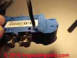
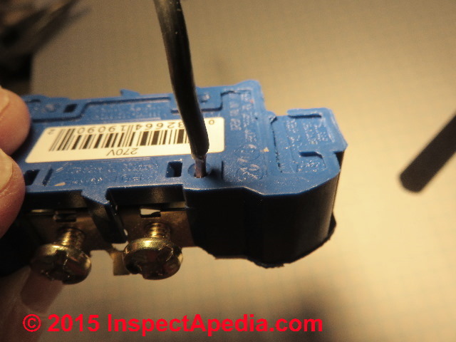
At page top we illustrate a #14 solid copper wire being pushed into the backwire opening of a common electrical receptacle. The wire has not been pushed fully into the connection as I wanted to show the diameter of the wire entering the push-in connector opening. Simple screw terminals are also visible in the lower left of the photo.
This article series illustrates and explains possible electrical failures and fire risk when using the push-in rear connectors on some back-wired electrical devices such as receptacles and switches. We illustrate the typical connector used in some receptacles and switches that accept a simple push-in connection usually found on the rear of the device. The rectangular opening is used to release an installed wire.
InspectAPedia tolerates no conflicts of interest. We have no relationship with advertisers, products, or services discussed at this website.
- Daniel Friedman, Publisher/Editor/Author - See WHO ARE WE?
Comparing Clamping Force in Two Electrical Wire-to-Connector Devices: Back-wired Spring-Clip vs. Binding Head Screw
Why is Electrical Connector Clamping Force Important?

[Click to enlarge any image]
Force in an electrical contact is important because as experts have pointed out, when we examine an electrical contact at very high magnification we learn that the contact surfaces are in fact not smooth but bumpy such that electrical current must actually flow through a myriad of bump-contact-points between the two surfaces.
Here we compare estimates of the connection force exerted by a spring clip wire connector such as the device shown abovce and a binding head screw wire connector. Stronger contact surface force means a more reliable contact and better connector performance, or as Dr. Aronstein puts it
The actual area of physical contact in the connections is directly proportional to the clamping force, exerted by either the screw or the spring or the screw. [Private email JA to DF 26 November 2015]
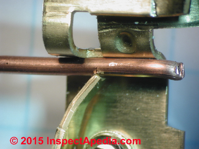
At BACKWIRED DEVICE SPRING CLIP DETAILS we describe the spring-clip connector used in push-in type back-wired electrical receptacles that rely on a spring rather than a screw to hold the electrical wire in place.
At WIRE-TO-CONNECTOR LIMITATIONS in PUSH-IN ELECTRICAL CONNECTORS we describe some limitations of spring-clip type electrical connectors including the risk of achieving only a rather small electrical contact surface between the electrical wire and the connector. In both of those articles we cite the critical importance of the combination of both contact area and contact force in establishing a good electrical connection between a wire and the connecting device.
At RECEPTACLE WIRE-TO-CONNECTOR CONTACT AREA SIZES we compare the areas of wire-to-receptacle contacts on electrical receptacles and in that article we noted that
The mechanical area of contact [between a wire and an electrical connector] is often very much less than that deductible from bulk properties.
and that a general way some engineers state the problem is
Contact Resistance is a function of (force x micro-contact points x other factors such as oxide resistance)
The indented italics above give three re-statements of the point that clamping force in an electrical connector is critical. So what is the connection's clamping force: the pressure exerted by the connecting device and the electrical wire?
With this question in mind we explored first a comparison of contact area comparing a screw connector with a spring-clip connector for electrical wire connections. At ELECTRICAL SCREW CONNECTOR TORQUE-FORCE I described some rough estimates of the torque force exerted when tightening a clamping-screw wire connector on a receptacle.
We continue that investigation with help from Jess Aronstein. Our correspondent expert, Dr. Jess Aronstein has kindly offered details about the measurement of the force exerted by the spring in a push-in type spring clip electrical connector.
The following is an excerpt from that correspondence in response to my question about the existence of research documenting the actual force exerted by the spring clip connector in a push-in backwired electrical receptalce or switch. Dr. Aronstein wrote:
I have not been able to find any data on the spring characteristics of the push-in receptacle contacts.
Estimates of the Contact Force or Clamping Force of Push-In Backwired Electrical Device Connectors
There is a simple way of estimating the contact force in the push-in backwired terminals, however. Measure the force needed to slide the wire in fully after it has initially been inserted enough to be under the spring. The initial insertion force is high, and then, once the spring is over the wire the force is essentially smooth and constant for the 1/4" or so of remaining insertion. That is the portion where you should measure the force.
Instead of a soft wire, however, use the smooth shank end of a hardened steel drill bit as a gage pin. Use a drill size that approximates the size of the wire that you are interested in. A 1/16" drill is approximately the same size as #14 AWG wire.
Using this method, I measured the four push-in terminals on each of two new receptacles that I happened to have here, one a P&S and the other a Leviton. The range was 2-1/4 lb to 3-1/2 lb, the average was about 3 lb.
The spring force is applied on one side of the wire and it is pressed against the contact plate with an equal force. The friction force that you have to overcome the sum of the resisting friction force at the two sliding points -- where the spring is pressing on the wire and where the wire is pressing on the contact plate. Assuming that the coefficient of friction is the same at both of these contact areas, then the push-in force that is measured is related to the spring force by the following equation:
F = 2uS
where
u = coefficient of friction
S = Spring force against the wire
A typical published value for non-lubricated steel/brass sliding coefficient of sliding friction is 0.5. Using that value the equation reduces to simply
F = S (for u=0.5)
So, the spring force is essentially equal to the push-in sliding force.
Typical Contact Force of a Clamp or Binding Head Screw Terminal for Connecting Electrical Wires to Devices
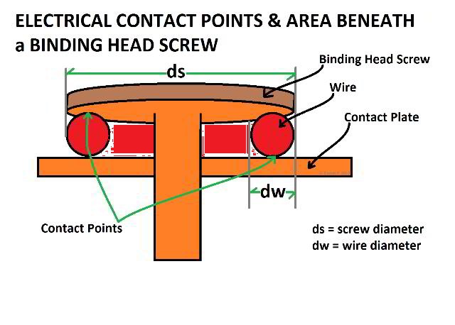
If we assume that the average torque applied to the screw (clamp or binding head) terminal 10 in-lb, then the clamping force is (according to the Kaiser Aluminum analysis) 225lb.
Comparison of Clamping Force: Screw Terminal Vs. Push-In Terminal
The actual area of physical contact in the connections is directly proportional to the clamping force, exerted by either the screw or the spring or the screw. Therefore, the ratio of actual area of contact at the current carrying interfaces is in the ratio of 225 to 3, which is to say that ...
There is of the order of 75x greater actual area of contact in a duplex receptacle wire termination at a screw terminal than in a push-in terminal of the types so far examined.
Resistance to Wire Pull-Out is Not a Predictor of Clamping Force
One question that is often asked is, "why it is so hard to pull the wire out, doesn't that show that the contact force is much higher?"
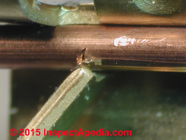
The answer is in the geometry of the connection, by which the spring notches into the copper wire and prevents pullout. That does not increase the contact force unless the pullout force is maintained. With the hardened steel drill shank used in the test the spring does not create a notch, and the pullout force is approximately the same as the push-in force.
I hope that helped answer your question about the relative actual contact area in the screw terminal vs. push-in. - J.A.
Comments on Electrical Resistance & Contact Pressure
Reviewer Comment:
My curiosity in reading the section still leads me back to electrical resistance, which is directly related to heat generation. I would not expect electrical resistance to be linearly related to contact pressure. Rather, from previous tests I’ve run I’d expect that resistance would increase until some contact pressure, and then change little as pressure continued to increased. Thus the increased pressure from one connector to another may or may not influence heating. - Lee Shields. by private email to D.F. 2015/12/09. Mr. Shields worked as a forensic engineer in the automotive industry and is a member of the editor's family.
Reply:
I expect Jess may agree with you; he has done seminal work on "micro-arcing" that is the actual basis for the increase in heat resistance and overheating and ultimately fires in electrical wiring. The arcing burns the surface and increases the resistance.
I don't think Jess is as concerned about micro-arcing on copper to copper connections however. I don't think the resistance changes so much over time as with AL wire. The articles I reviewed were focused on the micro-contact areas and my lay interpretation was that the contact pressure affected the number of micro-contact areas and implicitly resistance that might be more problematic if more current were flowing through too-few points of contact.
Perhaps contact area and pressure and resistance are all together in one formula. I'm looking into Babu (2001) and Timsit (1998) cited below.
References & Research on Electrical Contact Pressure & Resistance & Performance
- Aronstein, Jess,[Personal communication, J.A. to the editor (Daniel Friedman)], 26 November 2015. Dr. Jess Aronstein, protune@aol.com is a research consultant and an electrical engineer in Schenectady, NY. Dr. Aronstein provides forensic engineering services and independent laboratory testing for various agencies. Dr. Aronstein has published widely on and has designed and conducted tests on aluminum wiring failures, Federal Pacific Stab-Lok electrical equipment, and numerous electrical products and hazards.
See ALUMINUM WIRING BIBLIOGRAPHY and FPE HAZARD ARTICLES, STUDIESand also BACK-WIRED ELECTRICAL DEVICES for examples. - Babu SS, Santella ML, Feng Z, Riemer BW, Cohron JW. Empirical model of effects of pressure and temperature on electrical contact resistance of metals. Science and Technology of Welding & Joining. 2001 Jun 1;6(3):126-32.
Abstract
An important input property in the development of process models for resistance spot welding is electrical contact resistance. A model for the pressure and temperature dependence of electrical contact resistance was developed from established concepts of contact resistance.
The key to developing the desired relationship is determining surface roughness characteristics, which is experimentally problematic. To overcome this difficulty the electrical resistance of contacting interfaces was measured as a function of the pressure applied across the interfaces. Using known information about the temperature dependence of bulk resistivity and mechanical properties, a curve fitting procedure was used to establish the desired relationship of contact resistance to pressure and temperature.
This empirical model agrees well with experimental measurements in the regime of low applied pressure. At high pressures, predictions underestimate contact resistance, and this was attributed to strain hardening of asperities at the contacting interface. The model also predicts that the competing effects of bulk resistance and contact resistance will produce a peak in the variation of contact resistance with temperature.
The model provides a suitable means for incorporating the pressure and temperature dependence of contact resistance into process models of the resistance spot welding process. - Barber, J. R. "Bounds on the electrical resistance between contacting elastic rough bodies." In Proceedings of the Royal Society of London A: Mathematical, Physical and Engineering Sciences, vol. 459, no. 2029, pp. 53-66. The Royal Society, 2003.
Abstract:
A method is developed for placing bounds on the electrical contact conductance between contacting elastic bodies with rough surfaces. An analogy is first established between contact conductance and the incremental stiffness in the mechanical contact problem.
Results from contact mechanics and the reciprocal theorem are then used to bracket the mechanical load–displacement curve between those for two related smooth contact problems.
This enable bounds to be placed on the incremental stiffness and hence on the electrical conductance for the rough contact problem.
The method is illustrated by two simple examples, but its greatest potential probably lies in establishing the maximum effect of neglected microscales of roughness in a solution of the contact problem for bodies with multiscale or fractal roughness. - Chang, W. R., J. J. Hwang, F. B. Weng, and S. H. Chan. "Effect of clamping pressure on the performance of a PEM fuel cell." Journal of Power Sources 166, no. 1 (2007): 149-154.
- Kogut, L., and K. Komvopoulos. "Electrical contact resistance theory for conductive rough surfaces separated by a thin insulating film." Journal of applied physics 95, no. 2 (2004): 576-585.
- Kogut, L., and K. Komvopoulos. "Electrical contact resistance theory for conductive rough surfaces." Journal of Applied Physics 94, no. 5 (2003): 3153-3162.
Abstract:
A general electrical contact resistance (ECR) theory for conductive rough surfaces was derived from first principles. The analysis is based on fractal geometry for the surfacetopography description, elastic-plasticdeformation of contacting asperities, and size-dependent constriction resistance of microcontacts.
Relations for the ECR in terms of contact load and apparent contact area are obtained for isotropic, homogeneous, conductive surfaces with known material properties and surfacetopography. Useful design guidelines for electrical contacts are extracted from the numerical results.
A general relation between the dimensionless real contact area and the dimensionless ECR is introduced for lightly loaded contacts that depends only on the electron mean free path. Approaches for determining the surface roughness, material properties, and real contact area are discussed in the context of relatively simple ECR measurements. - Pascual JI, Mendez J, Gómez-Herrero J, Baró AM, Garcia N, Binh VT. Quantum contact in gold nanostructures by scanning tunneling microscopy. Physical review letters. 1993 Sep 20;71(12):1852.
- RECEPTACLE WIRE-TO-CONNECTOR CONTACT AREA SIZES - measurements & calculations of the contact area between an electrical wire and the connecting device on an electrical receptacle or switch explain differences between push-in type backwire connectors, compression plate connectors, and binding head screw connectors, all of which are found on many electrical receptacles and switches.
- Also seeReferences or Citations
- Slade PG, editor. Electrical contacts: principles and applications. CRC Press; 2013 Dec 17.
- Timsit, Roland S. "Electrical contact resistance: properties of stationary interfaces." In Electrical Contacts, 1998. Proceedings of the Forty-Fourth IEEE Holm Conference on, pp. 1-19. IEEE, 1998.
Abstract:
The paper reviews the dependence of electrical contact resistance on the shape and dimensions of /spl alpha/-spots and on the magnitude of the mechanical contact load. The range of validity of the classical voltage-temperature relation for electrical contacts is also examined.
The paper describes experimental evidence of breakdown of the classical electrical theory when /spl alpha/-spots become too small.
One of the interesting and useful properties of relatively small /spl alpha/-spots is that they are subject to large surface stresses. These stresses induce /spl alpha/-spot growth. - UL 486A - 486B STANDARD for SAFETY [PDF] (2013) retrieved 2019/11/20 original source: http://www.pts.ir/panel/images/post/43vdc1zrlyUL%20486a-486b-2013.pdf
- UL, ELECTRICAL CONNECTIONS [PDF] (2013), retrieved 2019/11/20 original source: https://legacy-uploads.ul.com/wp-content/uploads/sites/40/2015/02/Electrical-Connections-Issue-2-2013.pdf
Excerpt:
... for Safety for Wire Connectors) and should only be used in the absence of a manufacturer’s torque value either marked on the wire connector or identified within the installation instructions. I
f it should become necessary to use Annex I for field connections, the values in Column B would be the appropriate torque values to use. - Vogler M, Sheppard S. Electrical contact resistance under high loads and elevated temperatures. surfaces. 1993 Jun 1;9(10):11.
...
Continue reading at RECEPTACLE WIRE-TO-CONNECTOR CONTACT AREA SIZES for a discussion of the areas of wire-to-receptacle contacts on electrical receptacles, or select a topic from the closely-related articles below, or see the complete ARTICLE INDEX.
Or see these
Recommended Articles
- BACK-WIRED ELECTRICAL DEVICES - home
- BACKWIRED RECEPTACLE FAILURE PHOTOS
- BACKWIRED RECEPTACLE FAILURE REPORT
- BACK-WIRING FAQs for RECPTACLES & SWITCHES
- RECEPTACLE WIRE-TO-CONNECTOR CONTACT AREA SIZES
- WIRE-TO-CONNECTOR FORCE COMPARISONS
- WIRE-TO-CONNECTOR PERFORMANCE SUMMARY
Suggested citation for this web page
WIRE-TO-CONNECTOR FORCE COMPARISONS at InspectApedia.com - online encyclopedia of building & environmental inspection, testing, diagnosis, repair, & problem prevention advice.
Or see this
INDEX to RELATED ARTICLES: ARTICLE INDEX to ELECTRICAL INSPECTION & TESTING
Or use the SEARCH BOX found below to Ask a Question or Search InspectApedia
Ask a Question or Search InspectApedia
Share this article:Questions & answers or comments about how to install and wire electrical outlets or receptacles in buildings.
Search the InspectApedia website
Need to make a private comment? Email editor@inspectApedia.com. We welcome email with your website content critique, corrections, suggestions or questions. Email is monitored daily but our workload may prevent an immediate reply. For immediate results, we hope you'll first try asking your question using the search box just above.
Citations & References
In addition to any citations in the article above, a full list is available on request.
- Timothy Hemm has provided photographs of various electrical defects used at the InspectAPedia TM Website. Mr. Hemm is a professional electrical inspector in Yucala, CA.
- Mark Cramer Inspection Services Mark Cramer, Tampa Florida, Mr. Cramer is a past president of ASHI, the American Society of Home Inspectors and is a Florida home inspector and home inspection educator. Mr. Cramer serves on the ASHI Home Inspection Standards. Contact Mark Cramer at: 727-595-4211 mark@BestTampaInspector.com
- John Cranor [Website: /www.house-whisperer.com ] is an ASHI member and a home inspector (The House Whisperer) is located in Glen Allen, VA 23060. He is also a contributor to InspectApedia.com in several technical areas such as plumbing and appliances (dryer vents). Contact Mr. Cranor at 804-873-8534 or by Email: johncranor@verizon.net
- [3] NFPA - the National Fire Protection Association can be found online at www.nfpa.org
- [4] The NEC National Electrical Code (ISBN 978-0877657903) - NFPA might provide Online Access but you'll need to sign in as a professional or as a visitor)
- US NEC Free Access: See up.codes at this link: https://up.codes/code/nfpa-70-national-electrical-code-2020
- [5] Special thanks to our reader Steve who pointed out prior errors in our illustrations.
- [6] Simpson Strong-Tie, "Code Compliant Repair and Protection Guide for the Installation of Utilities in Wood Frame Construction", web search 5/21/12, original source strongtie.com/ftp/fliers/F-REPRPROTECT09.pdf, [copy on file as /Structures/Framing/Simpson_Framing_Protectors.pdf ]. "The information in this guide is a summary of requirements from the 2003, 2006 and 2009 International Residential Code (IRC), International Building Code (IBC), International Plumbing Code (IPC), International Mechanical Code (IMC), 2006 Uniform Plumbing Code (UPC) and the 2005 National Electrical Code."
- "Home Wiring Inspection," Roswell W. Ard, Rodale's New Shelter, July/August, 1985 p. 35-40.
- "Evaluating Wiring in Older Minnesota Homes," Agricultural Extension Service, University of Minnesota, St. Paul, Minnesota 55108.
- In addition to citations & references found in this article, see the research citations given at the end of the related articles found at our suggested
CONTINUE READING or RECOMMENDED ARTICLES.
- Carson, Dunlop & Associates Ltd., 120 Carlton Street Suite 407, Toronto ON M5A 4K2. Tel: (416) 964-9415 1-800-268-7070 Email: info@carsondunlop.com. Alan Carson is a past president of ASHI, the American Society of Home Inspectors.
Thanks to Alan Carson and Bob Dunlop, for permission for InspectAPedia to use text excerpts from The HOME REFERENCE BOOK - the Encyclopedia of Homes and to use illustrations from The ILLUSTRATED HOME .
Carson Dunlop Associates provides extensive home inspection education and report writing material. In gratitude we provide links to tsome Carson Dunlop Associates products and services.
 |
HOME | ABOUT | ASK a QUESTION | CONTACT | CONTENT USE POLICY | DESCRIPTION | POLICIES | PRIVACY | |
| © 2026 - 1985 Publisher InspectApedia.com - Daniel Friedman | |||||||||