 Electrical Receptacle (wall plugs) & Switch Back-wiring FAQs
Questions & answers about use of back-wired receptacles or switches
- POST a QUESTION or COMMENT about wiring connections used on electrical outlets or receptacles in buildings.
Electrical receptacle & switch backwiring questions & answers:
Questions & answers about backwiring or back-wiring of electrical receptacles and switches. Is backwiring OK or just easier and faster than using a screw connector? Is back-wiring reliable and safe?
This article series describes types of wire connectors on electrical receptacles and switches, compares their contact area and clamping force differences and offers conclusions about the most-reliable connectors to use.
This electrical wiring & receptacle article series explains receptacle types, receptacle grounding, connecting wires to the right receptacle terminal screws, electrical wire size, electrical wire color codes, and special receptacles for un-grounded circuits.
InspectAPedia tolerates no conflicts of interest. We have no relationship with advertisers, products, or services discussed at this website.
- Daniel Friedman, Publisher/Editor/Author - See WHO ARE WE?
FAQs about Back-Wiring Electrical Receptacles & Switches
 On 2018-11-07 by Anonymous - so we should only ever use the side screws to connect wires to a receptacle or switch?
So the bottom line is, only use the screws.
On 2018-11-08 by (mod) - no, clamp type back wiring works ok.
Anon:
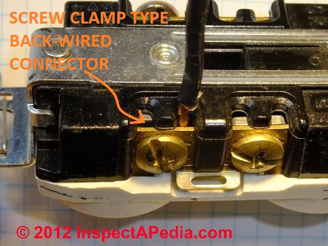
Not exactly, Anon. There are some back-wire electrical receptacles that use a screw-activated clamp that makes excellent wire contact. We discuss that advice in the article above on this page. I'll re-post a photo below.
Reader Question: Is it safe to plug a 10-Amp A/C into an outlet that is back wired?
Is it safe to plug in an ac unit that runs 10 amps , into outlet that is backed wired, i had read that you don't like this method, the outlet is on third floor and is on a 15 amp breaker - Johnny B 5/2/w
Reply: Comparing Three Types of Backwired Receptacles: 20-A Clamp Type & 15-ASpring Type & Clamp Type Backwiring Devices
Johnny, that's an interesting question and one I'm scared to answer - by online posting one cannot assure the electrical safety of your building.
At BACK-WIRED ELECTRICAL DEVICES, 3 TYPES we illustrate three different types of electrical receptacles that can be wired from their back-side.
 Our photo illustrates a spec-grade 20-Amp, 125V rated electrical receptacle that looks as if it is "back-wired" - in fact while a wire can be wrapped around the terminal screws on this device, the screw is intended to be used to tighten a rectangular brass plate against a square metal nut (silver in color) that makes a very strong and positive connection over a good area of wire surface.
This receptacle is marked on its back surface as CU Wire Only - copper only.
That said, I agree that older, spring-type back-wired electrical connections (shown at below left) are not as reliable as connections made under a screw or clamp, as the total contact area between the back-wire spring edge and the wire surface is minimal.
Nevertheless, on a 15-A circuit using 15-A devices such as receptacles, the circuit and its devices are rated and intended to be able to support the 10-amp load you describe, so long as the sum of all of the items plugged into that electrical circuit don't overload it.
Follow-up:
Thank you for responding, my town home was built in 1999, not sure if that is considered newer or older, lights do dim though when i use 10 amp vacuum . - Johnny B.
Reply:
Backwiring electrical receptacles is a permitted installation and might be found in a 1999 home - but as we show above, there are two different approaches, the second of which is a better quality installation and is in our opinion more reliable. See the details just below.
Push-in back-wire spring connector receptacle
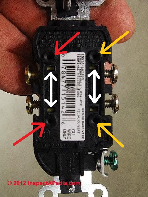
Contractor-grade 15-A spring-type-connector back-wired electrical receptacles (below left) provide a single opening at each of the four terminals (two neutral wires - yellow arrows, and two hot wires - red arrows) on the back of the receptacle.
The white arrows point to the smaller rectangular opening giving access to a press-to-release spring that will allow removal of the wire, but we prefer not to re-use this type of back-wired receptacle.
Tightening the screw at the main wire terminal (blue arrow) has nothing to do with the spring-clamp that is securing the back-wired terminal wire.
You can see that this receptacle also includes two binding head screw connectors on each side - silver screws for neutral wire (right side in the photo) and brass-coloured screws for hot or black wire (left side in the photo).
I consider these screws a more secure electrical connection than the push-in backwire connectors though of course a bit more labour is involved as well.
Insert & screw-clamp 15-A back-wire receptacle connectors
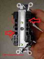
Some newer heavy-duty 15-A back-wired electrical receptacles (below-left) do not rely on a simple spring-edge to contact the electrical wire, as we illustrate in our photo below.
Rather, when the wire is inserted into any of 4 receiving holes on the back of the receptacle (red arrows) on the line side (black wire) and another 4 receiving openings on the load or neutral side (white wire) of the device..
When the terminal screw is tightened that actually snugs up a clamp that contacts a much larger surface area of the back-wired wire.
That's a more secure connection mechanically. On this receptacle, instead on a single back terminal accepting a single wire, there are a pair of back terminal openings at each of the four terminal screws.
Insert & screw-clamp 20-A back-wire receptacle connectors
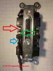
The 20-A rated electrical receptacle shown below is a variation on the 15-A pressure-clamp connector discussed just above. This receptacle dispenses with the round holes in the plastic receptacle back and exposes the wire clamps for a more clear view of what's happening.
The electrical wire (copper-only according to markings on these device) is inserted between a copper face plate (red arrow) and a thicker silver colored base plate (green arrow).
Turning the screw (blue arrow) at any of these four connectors (each of which will accept two wires) pinches the stripped wire-end between these two plates.
A comparison of crude contact areas between the copper wire and the different types of wire connectors is at RECEPTACLE WIRE-TO-CONNECTOR CONTACT AREA SIZES.
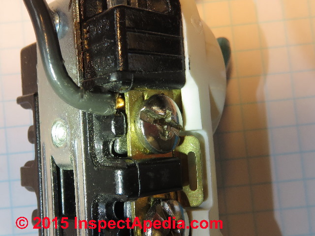
Below is a side-view of the tightened connector.
See WIRE-TO-CONNECTOR PERFORMANCE SUMMARY for our conclusions about the most reliable wire connections made at receptacles and switches.
Also see ELECTRICAL SCREW CONNECTOR TORQUE-FORCE
On 2018-11-07 by jeff
Very ,very good info, thank you.
On 2017-11-07 by (mod) - I have always felt that the spring "stab-in" type were a fire hazard for the lazy.
Tony, you make a good point, that the effect of small and maybe weak spring contact area against the copper wire in a daisy-chained circuit is probably cumulative. Thanks for adding that note.
On 2017-11-06 by Tony
I read your discussion on backwired receptacles with great interest, as I have always felt that the spring "stab-in" type were a fire hazard for the lazy.
Any house that I remodel gets all new receptacles and switches, with the wires wrapped around the screws.
Along with your "what if" of the curved wire, consider that if the wire is straightened by someone, they might do so with lineman's pliers or such, leaving ridges on the wire and, when stabbed in, hardly any contact area between the ridges and the spring assy.
In addition to your points on that page, there is the problem of the daisy-chained receptacles, wherein each one being stabbed in from one to the next results in the later and last in the chain having fed through several high-resistance connections.
Now, plug a vacuum or other high draw device into that last one and you have several small heaters in series and a device running on low voltage.
On 2017-09-24 by (mod) - if a connector is clearly designed to accept two wires then connecting two wires at that point will be code compliant.
Andy,
In my OPINION, yes, if a connector is clearly designed to accept two wires then connecting two wires at that point will be code compliant. You would connect the two wires just as you describe, avoiding having to crowd the box with an extra twist-on connector and pigtail.
On 2017-09-24 by Andy Pitman
For the screw and clamp type backwire terminals that can accept 2 conductors, is it considered code-compliant to actually connect 2 conductors?
So instead of splicing 2 same-colored wires in the box with a wire nut and running a pigtail to the device, can I simply connect the two to the same terminal and be done with it?
On 2017-07-06 by M. White
I notice that the electric inspection sticker inside the breaker box of my shop says occupancy only. This is a work space. Is this a problem?
Just got electric for my new shop building - I hired an electrician. I have about 8 outlets, all of them are gfci. Is this normal? Also they were back wired. Some of the tools I run are 15 amp. Should I have him come back and rewire the outlets? Thanks.
On 2016-11-30 2 by Kbreef
Can both the back wire clamps and side screws be used to join a electrical circuit from one duplex receptacle to the next one in the circuit ?
On 2016-08-23 by (mod) - push-back-wired receptacle failiures: look at the objective data not just personal opinion or "alternative" (hence un-supported" "facts"
Thanks for your opinion, Jeff. If you're like most contractors, few of us ever go back to a job 10, 20, or 40 years later to evaluate the longevity of our work.
There is not a shred of doubt that a back-wired receptacle, the older ones that is that relied on a simple spring clip contact, made a poor electrical connection - just the very edge of a small flat spring touching the wire, and that the connection was nowhere as reliable as one made under a binding head screw.
See, for example,
- Aronstein, J. (1993), “Evaluation of Receptacle Connections and Contacts,” Proc. 39th IEEE Holm Conf. on Electrical Contacts, IEEE, pp. 253–260.
As for why UL passes devices, there is a variety of answers to that one including that field experience and field failure reports sometimes have to accumulate for some time before code writers learn to make changes and improvements.
Take a look at the fact that the NEC and other codes are updated every few years; take a look too at the current on-market back-wired devices to see changes in the design of all but the cheapest ones. And keep in mind that often codes and standards are written by members of the very industry that they serve.
InspectAPedia is an independent publisher of building, environmental, and forensic inspection, diagnosis, and repair information provided free to the public - we have no business nor financial connection with any manufacturer or service provider discussed at our website.
We are dedicated to making our information as accurate, complete, useful, and unbiased as possible: we very much welcome critique, questions, or content suggestions for our web articles.
Working together and exchanging information makes us better informed than any individual can be working alone.
On 2016-08-22 by Jeff Edikngton - I have never had a switch or receptacle overheat due to a loose connection
I have been at the electrical trade for over 50 years and have installed thousands of push wired switches and receptacles. I have never had a switch or receptacle overheat due to a loose connection when push wired.
I always tugged on the wires to assure that they were wedged in good. My feelings are that when you side wire a receptacle or switch and start to wiggle and push the receptacle or switch in the box that it could cause the screws to loosen up from that twisting and turning.
Either way a loose connection could happen either way. If it was unsafe why would UL pass the device. They have been in use for 50 years or more. I would not want to do any wireing that would jeprodize anyones safety.
On 2015-10-26 by (mod) -
You bet, Markus. Thanks to Dr. Jess Aronstein who forwarded photos to us I've added both an image of the spring clip contact against the inserted wire in a back-wired receptacle as well as a sketch explaining how a screw clamp style clip offers more contact area.
On 2015-10-24 by Markus
Is there a picture somewhere that shows the flimsy spring clip contact against the inserted wire? I have a hard time convincing friends that the large and secure contact area of the clamp style backwire outlet is superior to the spring clamp.
Reader Question: I'm changing a wall plug and the wires are too thick to go through the holes on the back of the new device.
(June 3, 2014) William said:
I am changing a wall plug with a double plug but the wires are too thick to go through the hole of the new device. HOW can I resolve this?
Reply:
Use the screw terminals not the backward device.
Newer receptacles and switches that permit push-in back-wired connections usually have a small opening that will only accept #14 copper wire.
It appears that manufacturers don't want you to use #12 copper nor any aluminum wire in these devices. Aside from other performance issues raised in this article series, we were concerned (speaking for me not manufacturers) that an older device back-wired with #12 copper might later have the #12 wire removed and still later someone may insert a smaller #14 copper wire into the same opening.
Because the spring-clip connector was earlier pushed to accommodate the larger #12 wire one would worry that the same spring may no longer apply sufficient clamping force when a smaller #14 wire is inserted.
Furthermore the process of removal of the #12 wire from the spring-clip connector may also have affected its clamping force, either by the pressure on the release portion of the spring or because a gorilla pulled out the older wire by sheer force (not an easy task).
Watch out. What are those large diameter wires? If aluminum you have a bigger safety hazard to address.
See BACK-WIRED ELECTRICAL DEVICES.
See ALUMINUM WIRING HAZARDS & REPAIRS - home
Also see HOW to CONNECT WIRES to a RECEPTACLE or SWITCH for details on how to make the physical connections.
Question: what do I do with the screws to which no wire is connected on a conventional "plug" (wall receptacle)?
At the end of a circuit, I'm only using 2 of the 4 screws on a conventional plug. What should I do with the 2 unused screws? Should they be screwed all the way in? Or left partially unscrewed? Or does it matter? - Chris Rasko 7/8/12
Reply:
Chris:
regarding the un-used screw terminals on an electrical receptacle, you should simply screw them all the way in and leave them alone. Don't remove the screws - it's not necessary, they are deliberately hard to remove completely, and they could be needed in some future wiring change.
See
...
Continue reading at BACK-WIRED ELECTRICAL DEVICES - home or select a topic from the closely-related articles below, or see the complete ARTICLE INDEX.
Or see these
Recommended Articles
- BACK-WIRED ELECTRICAL DEVICES - home
- BACKWIRED RECEPTACLE FAILURE PHOTOS
- BACKWIRED RECEPTACLE FAILURE REPORT
- ELECTRICAL OUTLET, HOW TO ADD & WIRE - home - for general wiring procedures, connections & advice for connecting electrical receptacles.
- RECEPTACLE WIRE-TO-CONNECTOR CONTACT AREA SIZES
- WIRE-TO-CONNECTOR FORCE COMPARISONS
- WIRE-TO-CONNECTOR PERFORMANCE SUMMARY
Suggested citation for this web page
BACK-WIRING FAQs for RECPTACLES & SWITCHES at InspectApedia.com - online encyclopedia of building & environmental inspection, testing, diagnosis, repair, & problem prevention advice.
Or see this
INDEX to RELATED ARTICLES: ARTICLE INDEX to ELECTRICAL INSPECTION & TESTING
Or use the SEARCH BOX found below to Ask a Question or Search InspectApedia
Ask a Question or Search InspectApedia
Questions & answers or comments about how to install and wire electrical outlets or receptacles in buildings.
Try the search box just below, or if you prefer, post a question or comment in the Comments box below and we will respond promptly.
Search the InspectApedia website
Note: appearance of your Comment below may be delayed: if your comment contains an image, photograph, web link, or text that looks to the software as if it might be a web link, your posting will appear after it has been approved by a moderator. Apologies for the delay.
Only one image can be added per comment but you can post as many comments, and therefore images, as you like.
You will not receive a notification when a response to your question has been posted.
Please bookmark this page to make it easy for you to check back for our response.
IF above you see "Comment Form is loading comments..." then COMMENT BOX - countable.ca / bawkbox.com IS NOT WORKING.
In any case you are welcome to send an email directly to us at InspectApedia.com at editor@inspectApedia.com
We'll reply to you directly. Please help us help you by noting, in your email, the URL of the InspectApedia page where you wanted to comment.
Citations & References
In addition to any citations in the article above, a full list is available on request.
- Timothy Hemm has provided photographs of various electrical defects used at the InspectAPedia TM Website. Mr. Hemm is a professional electrical inspector in Yucala, CA.
- Mark Cramer Inspection Services Mark Cramer, Tampa Florida, Mr. Cramer is a past president of ASHI, the American Society of Home Inspectors and is a Florida home inspector and home inspection educator. Mr. Cramer serves on the ASHI Home Inspection Standards. Contact Mark Cramer at: 727-595-4211 mark@BestTampaInspector.com
- John Cranor [Website: /www.house-whisperer.com ] is an ASHI member and a home inspector (The House Whisperer) is located in Glen Allen, VA 23060. He is also a contributor to InspectApedia.com in several technical areas such as plumbing and appliances (dryer vents). Contact Mr. Cranor at 804-873-8534 or by Email: johncranor@verizon.net
- [3] NFPA - the National Fire Protection Association can be found online at www.nfpa.org
- [4] The NEC National Electrical Code (ISBN 978-0877657903) - NFPA might provide Online Access but you'll need to sign in as a professional or as a visitor)
- US NEC Free Access: See up.codes at this link: https://up.codes/code/nfpa-70-national-electrical-code-2020
- [5] Special thanks to our reader Steve who pointed out prior errors in our illustrations.
- [6] Simpson Strong-Tie, "Code Compliant Repair and Protection Guide for the Installation of Utilities in Wood Frame Construction", web search 5/21/12, original source strongtie.com/ftp/fliers/F-REPRPROTECT09.pdf, [copy on file as /Structures/Framing/Simpson_Framing_Protectors.pdf ]. "The information in this guide is a summary of requirements from the 2003, 2006 and 2009 International Residential Code (IRC), International Building Code (IBC), International Plumbing Code (IPC), International Mechanical Code (IMC), 2006 Uniform Plumbing Code (UPC) and the 2005 National Electrical Code."
- "Electrical System Inspection Basics," Richard C. Wolcott, ASHI 8th Annual Education Conference, Boston 1985.
- "Simplified Electrical Wiring," Sears, Roebuck and Co., 15705 (F5428) Rev. 4-77 1977 [Lots of sketches of older-type service panels.]
- "How to plan and install electric wiring for homes, farms, garages, shops," Montgomery Ward Co., 83-850.
- "Simplified Electrical Wiring," Sears, Roebuck and Co., 15705 (F5428) Rev. 4-77 1977 [Lots of sketches of older-type service panels.]
- "Home Wiring Inspection," Roswell W. Ard, Rodale's New Shelter, July/August, 1985 p. 35-40.
- "Evaluating Wiring in Older Minnesota Homes," Agricultural Extension Service, University of Minnesota, St. Paul, Minnesota 55108.
- "Electrical Systems," A Training Manual for Home Inspectors, Alfred L. Alk, American Society of Home Inspectors (ASHI), 1987, available from ASHI. [DF NOTE: I do NOT recommend this obsolete publication, though it was cited in the original Journal article as it contains unsafe inaccuracies]
- "Basic Housing Inspection," US DHEW, S352.75 U48, p.144, out of print, but is available in most state libraries.
- In addition to citations & references found in this article, see the research citations given at the end of the related articles found at our suggested
CONTINUE READING or RECOMMENDED ARTICLES.
- Carson, Dunlop & Associates Ltd., 120 Carlton Street Suite 407, Toronto ON M5A 4K2. Tel: (416) 964-9415 1-800-268-7070 Email: info@carsondunlop.com. Alan Carson is a past president of ASHI, the American Society of Home Inspectors.
Thanks to Alan Carson and Bob Dunlop, for permission for InspectAPedia to use text excerpts from The HOME REFERENCE BOOK - the Encyclopedia of Homes and to use illustrations from The ILLUSTRATED HOME .
Carson Dunlop Associates provides extensive home inspection education and report writing material. In gratitude we provide links to tsome Carson Dunlop Associates products and services.


