
 Mobile Home or Doublewide Pier & Support Requirements
Installation, codes, Q&A
- POST a QUESTION or COMMENT about the structural components of mobile homes, doublewides, trailers.
Mobile home piers, masonry, steel pyramids, pads: codes, examples, Q&A, on support pier height, clearance, extension limits, spacing, and installation instructions.
How to install, inspect, repair manufactured or mobile home piers, support systems, pads.
Special attention should be given to mobile home, double-wide or trailer to tie-downs, hurricane and storm damage prevention, and special connections are required between sections of double-wide and multi-wide mobile homes.
InspectAPedia tolerates no conflicts of interest. We have no relationship with advertisers, products, or services discussed at this website.
- Daniel Friedman, Publisher/Editor/Author - See WHO ARE WE?
Mobile Home Pier Foundation & Support Systems
 Here, after answering the four most-frequent reader questions about mobile home piers & support height, clearance and spacing, we provide the complete U.S. federal / HUD code specifications for support systems, piers, pads, etc. for manufactured or mobile homes, singlewides and doublewides.
Article Contents
- Question: MAXIMUM PIER HEIGHT
- Question: MAXIMUM FLOOR HEIGHT
- Question: MINIMUM CLEARANCE UNDER FLOOR
- Question: REQUIRED SPACING BETWEEN PIERS
- PIER/PAD SUPPORT CODE (Complete) Manufactured / Mobile Home Installation Standards section §3285
- § 3285.301 - GENERAL.
- § 3285.302 - FLOOD HAZARD AREAS.
- § 3285.303 - PIERS.
- § 3285.304 - PIER CONFIGURATION.
- § 3285.305 - CLEARANCE UNDER HOMES.
- § 3285.306 - DESIGN PROCEDURES FOR CONCRETE BLOCK PIERS.
- § 3285.307 - PERIMETER SUPPORT PIERS.
- § 3285.308 - MANUFACTURED PIERS.
- § 3285.309 - [Reserved]
- § 3285.310 - PIER LOCATION AND SPACING.
- § 3285.311 - REQUIRED PERIMETER SUPPORTS.
- § 3285.312 - FOOTINGS.
- § 3285.313 - COMBINATION SYSTEMS.
- § 3285.314 - [Reserved]
- § 3285.315 - SPECIAL SNOW LOAD CONDITIONS.
- MOBILE HOME PIER INSPECTION - separate article
- MOBILE HOME FOUNDATION CODES & STANDARDS
Maximum Mobile Home Pier Height
 2017/06/07 Ashley
What is the maximum height a mobile home can be from the ground?
This question was originally posted at MOBILE HOME CODES, STANDARDS & MANUALS
[Click to enlarge any image]
Reply:
Ashley,
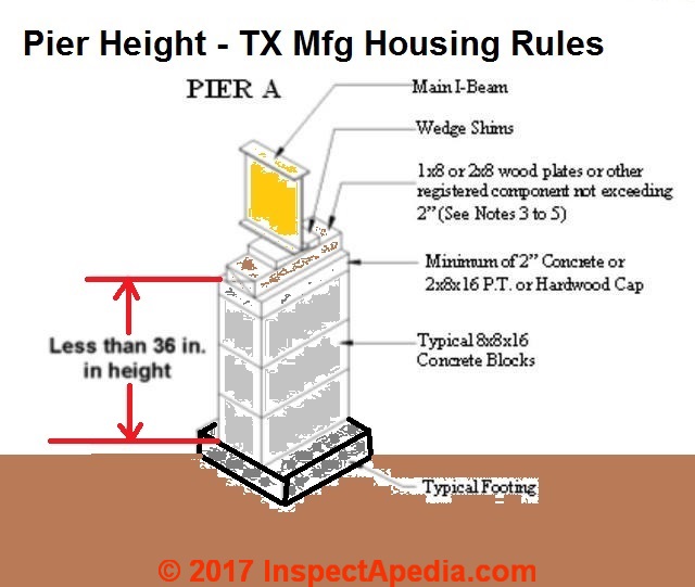
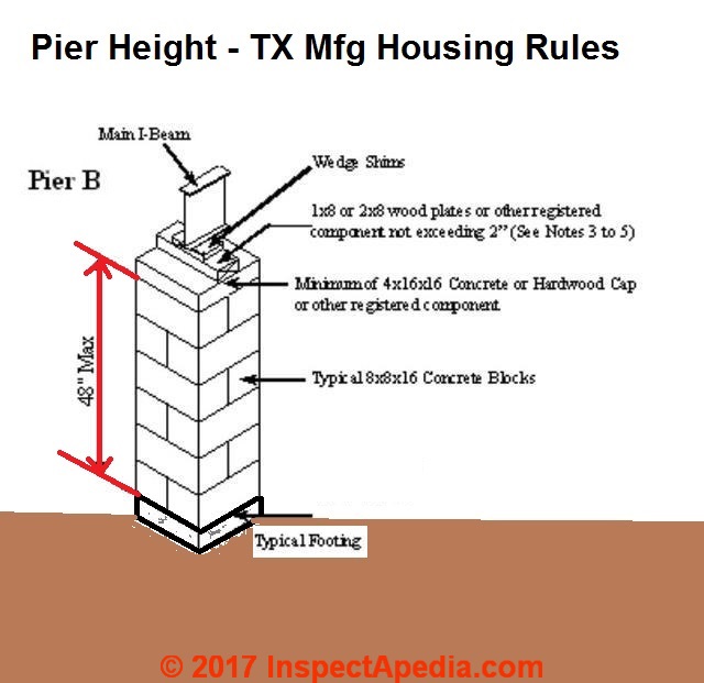
In general and historically, the maximum height from the surface of the pier to the top of the last concrete block which would be placed under a beam or girder supporting the manufactured or mobile home floor is 36 inches for a stack of single open-celled 8" concrete blocks [Pier A], or 48" for an interlocked concrete block pier - essentially a 2-block square as we illustrate here [Pier B].
The 2022 CFR code cited later on this page permits some pier heights up to 54".
Greater pier and thus foundation heights for mobile homes or manufactured homes may be permitted by codes and standards but will likely require an engineer's sign-off and of course local code-official approval.
Maximum Manufactured home floor structure height above ground level
Pier A: Single stack of solid or open cell, 8x8x16 concrete blocks. Maximum height is 36 inches as measured from the top of the footer to the top of the last concrete block for single-stacks of open-cell 8x8x16" concrete blocks.
Concrete blocks are installed with their lengths perpendicular to the main I-Beam Open cells must be vertical and in alignment. - Texas (2014)
Pier B: Interlocked double stack of solid or open cell 8x8x16 concrete blocks. The maximum height is 48 inches as measured from the top of the footer to the top of the last concrete block.
Piers of greater heights are allowed if they are within limits established in adopted federal standards.
The pier is capped with a minimum 16x16x4 concrete cap.
Open cells must be vertical and in alignment.
Each course of open cell blocks must be perpendicular to the previous course. - Texas (2014)
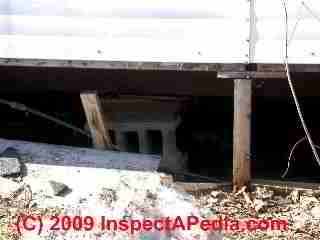
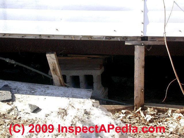
Minimum Clearance Between Manufactured Home Floor Structure & Ground?
The minimum ground clearance allowed from the bottom of the floor joists to the ground surface is 18 inches. Here is an example citation for U.S. manufactured homes excerpted from the Texas code:
If the manufactured home is installed according to the state's generic standards, a minimum clearance of 18 inches between the ground and the bottom of the floor joists must be maintained.
In addition, the installer shall be responsible for installing the home with sufficient clearance between the I-Beams and the ground so that after the crossover duct prescribed by the manufacturer is properly installed it will not be in contact with the ground.
Refer to §80.25 of this chapter (relating to Generic Standards for Multi-Section Connections Standards) for additional requirements for utility connections.
The Installer must remove all debris, sod, tree stumps and other organic materials from all areas where footings are to be located. - Texas (2014)
Depending on where you live there may be local regulations that differ.
Also keep in mind that the tie-down or stabilization system required for mobile homes, particularly in high-wind areas, will set practical limits on mobile home heights from the ground in that the tiedown systems have their own particular dimensions, anchor point requirements, and installation specifications.
What is the Required Spacing for Mobile Home Piers?
§ 3285.310 - Pier location and spacing.
(a) The location and spacing of piers depends upon the dimensions of the home, the live and dead loads, the type of construction (single-or multi-section), I-beam size, soil bearing capacity, footing size, and such other factors as the location of doors or other openings.
(b) Mate-line and column pier supports must be in accordance with this subpart and consistent with Figures A through C to this section, unless the pier support and footing configuration is designed by a registered professional engineer or registered architect.
(c) Piers supporting the frame must be no more than 24 inches from both ends and not more than 120 inches center to center under the main rails.
(d) Pier support locations. Pier support locations and spacing must be presented to be consistent with Figures A and B to § 3285.312, as applicable, unless alternative designs are provided by a professional engineer or registered architect in accordance with acceptable engineering practice.
Notes:
- Bottom of footings must extend below frost line depth, unless designed for placement above the frost line. (See § 3285.312(b)).
- Piers may be offset up to 6 in. in either direction along the supported members to allow for plumbing, electrical, mechanical, equipment, crawlspaces, or other devices.
- Single-stack concrete block pier loads must not exceed 8,000 lbs.
- Prefabricated piers must not exceed their approved or listed maximum vertical or horizontal design loads.
- When a full-height mating wall does not support the ridge beam, this area is considered an unsupported span - Span B.
- Piers are not required at openings in the mating wall that are less than 48 inches in width.
Place piers on both sides of mating wall openings that are 48 inches or greater in width. - For roof loads of 40 psf or greater, a professional engineer or registered architect must determine the maximum mating wall opening permitted without pier or other supports.
- In areas where the open span is greater than 10 ft., intermediate piers and footings must be placed at maximum 10 ft. on center.
- Column piers are in addition to piers required under full-height mating walls.
- Mate-line column support piers are installed with the long dimension of the concrete block perpendicular to the rim joists.
- Pier and footing designed to support both floor sections. Loads as listed in Table 3 to § 3285.303 are total column loads for both sections.
HUD/FHA Manufactured Home foundation requirements
HUD/FHA Manufactured Home foundation requirements add specifications that may be beyond the minimum standards specified by manufactured home producers, including the following:
- The foundation or footing below the piers described above must be made of reinforced concrete that extend below the frost line
- Piers must be constructed of solid materials - that is, the hollow-core concrete blocks described in the Texas code are not permitted. Piers can be made of solid concrete block, reinforced concrete, treated wood posts, or steel posts.
Mobile Home Perimeter Support & Pier Code
The regulations pertaining to mobile / manufactured home support systems - piers, pads, etc. are given below on this page; you an also download this entire code as a PDF file at:
- (HUD) TITLE 24, SUBTITLE B, CHAPTER XX, PART 3285 MODEL MANUFACTURED HOME INSTALLATION STANDARDS (2022) [PDF] - retrieved 2022/05/25, original source: https://www.ecfr.gov/current/title-24/subtitle-B/chapter-XX/part-3285
The following U.S. mobile / manufactured home code sections describe the requirements for support piers as given in Title 24 - Housing and Urban Development last revised: May 17, 2022
§ 3285.301 - General.
(a) Foundations for manufactured home installations must be designed and constructed in accordance with this subpart and must be based on site conditions, home design features, and the loads the home was designed to withstand, as shown on the home's data plate.
(b) Foundation systems that are not pier and footing type configurations may be used when verified by engineering data and designed in accordance with § 3285.301(d), consistent with the design loads of the MHCSS.
Pier and footing specifications that are different than those provided in this subpart, such as block size, metal piers, section width, loads, and spacing, may be used when verified by engineering data that comply with §§ 3285.301(c) and (d) and are capable of resisting all design loads of the MHCSS.
(c) All foundation details, plans, and test data must be designed and certified by a registered professional engineer or registered architect, and must not take the home out of compliance with the MHCSS. (See 3285.2)
(d) Alternative foundation systems or designs are permitted in accordance with either of the following:
(1) Systems or designs must be manufactured and installed in accordance with their listings by a nationally recognized testing agency, based on a nationally recognized testing protocol; or
(2) System designs must be prepared by a professional engineer or a registered architect or tested and certified by a professional engineer or registered architect in accordance with acceptable engineering practice and must be manufactured and installed so as not to take the home out of compliance with the Manufactured Home Construction and Safety Standards (part 3280 of this chapter).
§ 3285.302 - Flood hazard areas.
In flood hazard areas, foundations, anchorings, and support systems must be capable of resisting loads associated with design flood and wind events or combined wind and flood events, and homes must be installed on foundation supports that are designed and anchored to prevent floatation, collapse, or lateral movement of the structure. Manufacturer's installation instructions must indicate whether:
(a) The foundation specifications have been designed for flood-resistant considerations, and, if so, the conditions of applicability for velocities, depths, or wave action; or
(b) The foundation specifications are not designed to address flood loads.
§ 3285.303 - Piers.
(a) General. The piers used must be capable of transmitting the vertical live and dead loads to the footings or foundation.
(b) Acceptable piers - materials specification. (1) Piers are permitted to be concrete blocks; pressure-treated wood with a water borne preservative, in accordance with AWPA Standard U1-04 (incorporated by reference, see § 3285.4) for Use Category 4B ground contact applications; or adjustable metal or concrete piers.
(2) Manufactured piers must be listed or labeled for the required vertical load capacity, and, where required by design, for the appropriate horizontal load capacity.
(c) Design requirements. (1) Load-bearing capacity. The load bearing capacity for each pier must be designed to include consideration for the dimensions of the home, the design dead and live loads, the spacing of the piers, and the way the piers are used to support the home.
(2) Center beam/mating wall support must be required for multi-section homes and designs must be consistent with Tables 2 and 3 to § 3285.303 and Figures A, B, and C to § 3285.310.
(d) Pier loads. (1) Design support configurations for the pier loads, pier spacing, and roof live loads must be in accordance with Tables 1, 2, and 3 to § 3285.303 and the MHCSS. Other pier designs are permitted in accordance with the provisions of this subpart.
(2) Manufactured piers must be rated at least to the loads required to safely support the dead and live loads, as required by § 3285.301, and the installation instructions for those piers must be consistent with Tables 1, 2, and 3 to this section.
Table 1 to § 3285.303 - Frame Blocking Only/Perimeter Support Not Required Except at Openings
[Click to enlarge any of these tables]
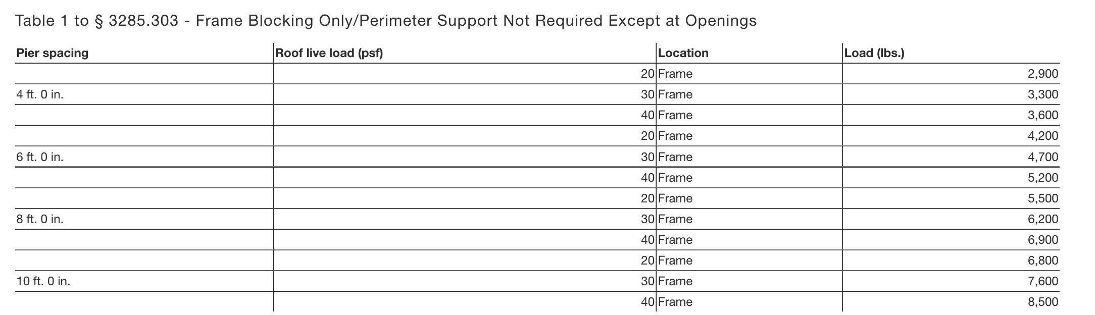
Notes to Table 1 to § 3285.303
1. See Table to § 3285.312 for cast-in-place footing design by using the noted loads.
2. Table 1 is based on the following design assumptions: maximum 16 ft. nominal section width (15 ft. actual width), 12” eave, 10” I-beam size, 300 lbs. pier dead load, 10 psf roof dead load, 6 psf floor dead load, 35 plf [per linear foot] wall dead load, and 10 plf chassis dead load.
3. Interpolation for other pier spacing is permitted.
4. The pier spacing and loads shown in the above table do not consider flood or seismic loads and are not intended for use in flood or seismic hazard areas. In those areas, the foundation support system is to be designed by a professional engineer or architect.
5. See Table to § 3285.312 for sizing of footings.
Table 2 to § 3285.303 - Frame Plus Perimeter Blocking/Perimeter Blocking Required
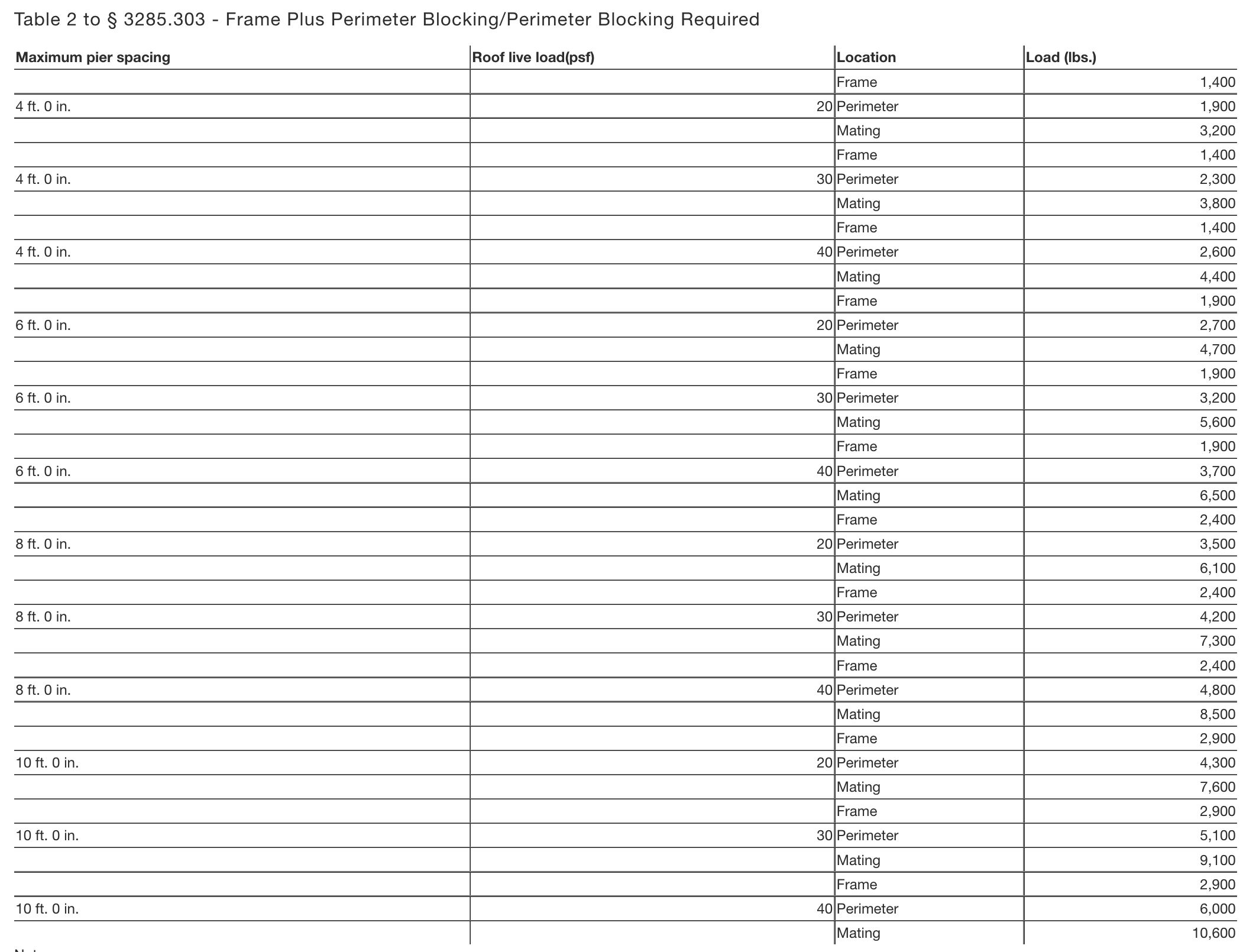
Notes to Table 2 to § 3285.303
1. See Table to § 3285.312for cast-in-place footing design by using the noted loads.
2. Mating wall perimeter piers and footings only required under full height mating walls supporting roof loads. Refer to Figures A and B to § 3285.310.
3. Table 2 is based on the following design assumptions: maximum 16 ft. nominal section width (15 ft. actual width), 12” eave, 10” I-beam size, 300 lbs. pier dead load, 10 psf roof dead load, 6 psf floor dead load, 35 plf wall dead load, and 10 plf chassis dead load.
4. Interpolation for other pier spacing is permitted.
5. The pier spacing and loads shown in the above table do not consider flood or seismic loads and are not intended for use in flood or seismic hazard areas. In those areas, the foundation support system is to be designed by a professional engineer or architect.
6. See Table to § 3285.312or sizing of footings.
Table 3 to § 3285.303 - Ridge Beam Span Footing Capacity
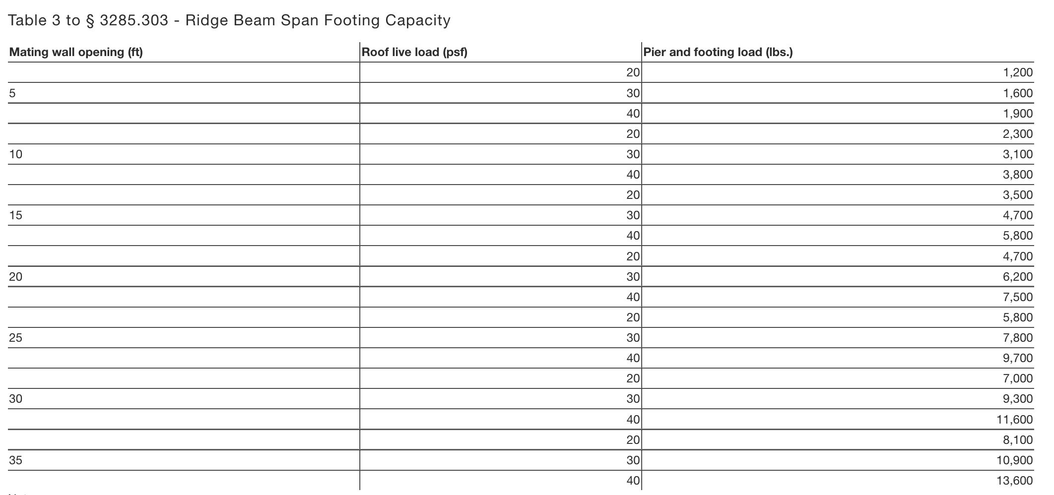
Notes to Table 3 to § 3285.303
1. See Table to § 3285.312 for cast-in-place footing design by using the noted loads.
2. Table 3 is based on the following design assumptions: maximum 16 ft. nominal section width (15 ft. actual width), 10″ I-beam size, 300 lbs. pier dead load, 10 psf roof dead load, 6 psf floor dead load, 35 plf wall dead load, and 10 plf chassis dead load.
3. Loads listed are maximum column loads for each section of the manufactured home.
4. Interpolation for maximum allowable pier and column loads is permitted for mate-line openings between those shown in the table.
5. The pier spacing and loads shown in the above table do not consider flood or seismic loads and are not intended for use in flood or seismic hazard areas. In those areas, the foundation support system must be designed by a professional engineer or registered architect.
6. See Table to § 3285.312 for sizing of footings.
§ 3285.304 - Pier configuration.
(a) Concrete blocks.
Installation instructions for concrete block piers must be developed in accordance with the following provisions and must be consistent with Figures A and B to § 3285.306.
(1) Load-bearing (not decorative) concrete blocks must have nominal dimensions of at least 8 inches × 8 inches × 16 inches;
(2) The concrete blocks must be stacked with their hollow cells aligned vertically; and
(3) When piers are constructed of blocks stacked side-by-side, each layer must be at right angles to the preceding one, as shown in Figure B to § 3285.306.
(b) Caps.
(1) Structural loads must be evenly distributed across capped-hollow block piers, as shown in Figures A and B to § 3285.306.
(2) Caps must be solid concrete or masonry at least 4 inches in nominal thickness, or hardboard lumber at least 2 inches nominal in thickness; or be corrosion-protected minimum one-half inch thick steel; or be of other listed materials.
(3) All caps must be of the same length and width as the piers on which they rest.
(4) When split caps are used on double-stacked blocks, the caps must be installed with the long dimension across the joint in the blocks below.
(c) Gaps.
Any gaps that occur during installation between the bottom of the main chassis beam and foundation support system must be filled by:
(1) Nominal 4 inch × 6 inch × 1 inch shims to level the home and fill any gaps between the base of the main chassis beam and the top of the pier cap;
(2) Shims must be used in pairs, as shown in Figures A and B to § 3285.306, and must be driven in tightly so that they do not occupy more than one inch of vertical height; and
(3) Hardwood plates no thicker than 2 inches nominal in thickness or 2 inch or 4 inch nominal concrete block must be used to fill in any remaining vertical gaps.
(d) Manufactured pier heights.
Manufactured pier heights must be selected so that the adjustable risers do not extend more than 2 inches when finally positioned.
§ 3285.305 - Clearance under homes.
A minimum clearance of 12 inches must be maintained between the lowest member of the main frame (I-beam or channel beam) and the grade under all areas of the home.
§ 3285.306 - Design procedures for concrete block piers.
(a) Frame piers less than 36 inches high. (1) Frame piers less than 36 inches high are permitted to be constructed of single, open, or closed-cell concrete blocks, 8 inches “ 8 inches “ 16 inches, when the design capacity of the block is not exceeded.
(2) The frame piers must be installed so that the long sides are at right angles to the supported I-beam, as shown in Figure A to this section.
(3) The concrete blocks must be stacked with their hollow cells aligned vertically and must be positioned at right angles to the footings.
(4) Horizontal offsets from the top to the bottom of the pier must not exceed one-half inch.
(5) Mortar is not required, unless specified in the installation instructions or required by a registered professional engineer or registered architect.
(b) Frame piers 36 inches to 67 inches high and corner piers. (1) All frame piers between 36 inches and 67 inches high and all corner piers over three blocks high must be constructed out of double, interlocked concrete blocks, as shown in Figure B to this section, when the design capacity of the block is not exceeded. Mortar is not required for concrete block piers, unless otherwise specified in the installation instructions or required by a professional engineer or registered architect.
(2) Horizontal offsets from the top to the bottom of the pier must not exceed one inch.
(c) All piers over 67 inches high. Piers over 67 inches high must be designed by a registered professional engineer or registered architect, in accordance with acceptable engineering practice. Mortar is not required for concrete block piers, unless otherwise specified in the manufacturer installation instructions or by the design.
§ 3285.307 - Perimeter support piers.
(a) Piers required at mate-line supports, perimeter piers, and piers at exterior wall openings are permitted to be constructed of single open-cell or closed-cell concrete blocks, with nominal dimensions of 8 inches × 8 inches × 16 inches, to a maximum height of 54 inches, as shown in Figure A to this section, when the design capacity of the block is not exceeded.
(b) Piers used for perimeter support must be installed with the long dimension parallel to the perimeter rail.
§ 3285.308 - Manufactured piers.
(a) Manufactured piers must be listed and labeled and installed to the pier manufacturer's installation instructions. See § 3285.303(d)(2) for additional requirements.
(b) Metal or other manufactured piers must be provided with protection against weather deterioration and corrosion at least equivalent to that provided by a coating of zinc on steel of .30 oz./ft. 2 of surface coated.
§ 3285.309 - [Reserved]
§ 3285.310 - Pier location and spacing.
(a) The location and spacing of piers depends upon the dimensions of the home, the live and dead loads, the type of construction (single-or multi-section), I-beam size, soil bearing capacity, footing size, and such other factors as the location of doors or other openings.
(b) Mate-line and column pier supports must be in accordance with this subpart and consistent with Figures A through C to this section, unless the pier support and footing configuration is designed by a registered professional engineer or registered architect.
(c) Piers supporting the frame must be no more than 24 inches from both ends and not more than 120 inches center to center under the main rails.
(d) Pier support locations. Pier support locations and spacing must be presented to be consistent with Figures A and B to § 3285.312, as applicable, unless alternative designs are provided by a professional engineer or registered architect in accordance with acceptable engineering practice.
Notes:
1. Bottom of footings must extend below frost line depth, unless designed for placement above the frost line. (See § 3285.312(b)).
2. Piers may be offset up to 6 in. in either direction along the supported members to allow for plumbing, electrical, mechanical, equipment, crawlspaces, or other devices.
3. Single-stack concrete block pier loads must not exceed 8,000 lbs.
4. Prefabricated piers must not exceed their approved or listed maximum vertical or horizontal design loads.
5. When a full-height mating wall does not support the ridge beam, this area is considered an unsupported span - Span B.
6. Piers are not required at openings in the mating wall that are less than 48 inches in width. Place piers on both sides of mating wall openings that are 48 inches or greater in width. For roof loads of 40 psf or greater, a professional engineer or registered architect must determine the maximum mating wall opening permitted without pier or other supports.
Notes:
1. Bottom of footings must be below the frost line depth, unless designed for placement above the frost line. (See § 3285.312(b)).
2. Piers may be offset 6 in. in either direction along supported members to allow for plumbing electrical, mechanical equipment, crawlspaces, or other devices.
3. Single stack concrete block pier loads must not exceed 8,000 lbs.
4. Piers are not required at openings in the mating wall that are less than 48 inches in width. Place piers on both sides of mating wall openings that are 48 inches or greater in width. For roof loads of 40 psf or greater, a professional engineer or registered architect must determine the maximum mating wall opening permitted without pier or other supports.
5. When a full-height mating wall does not support the ridge beam, this area is considered an unsupported span - Span B.
6. In areas where the open span is greater than 10 ft., intermediate piers and footings must be placed at maximum 10 ft. on center.
7. Prefabricated piers must not exceed their approved or listed maximum horizontal or vertical design loads.
8. Column piers are in addition to piers required under full-height mating walls.
Notes:
1. Mate-line column support piers are installed with the long dimension of the concrete block perpendicular to the rim joists.
2. Pier and footing designed to support both floor sections. Loads as listed in Table 3 to § 3285.303 are total column loads for both sections.
§ 3285.311 - Required perimeter supports.
(a) Perimeter pier or other supports must be located as follows:
(1) On both sides of side wall exterior doors (such as entry, patio, and sliding glass doors) and any other side wall openings of 48 inches or greater in width, and under load-bearing porch posts, factory installed fireplaces, and fireplace stoves).
(2) Other perimeter supports must be:
(i) Located in accordance with Table 2 to § 3285.303; or
(ii) Provided by other means such as additional outriggers or floor joists. When this alternative is used, the designs required by § 3285.301 must consider the additional loads in sizing the pier and footing supports under the main chassis beam.
(b) For roof live loads of 40 psf or greater, a professional engineer or architect must determine the maximum sidewall opening permitted without perimeter pier or other supports.
(c) The location and installation of any perimeter pier support must not take the home out of compliance with the Manufactured Home Construction and Safety Standards (part 3280 of this chapter).
Title 24 Housing and Urban Development Chapter XXPart 3285 Subpart D - Foundations
§ 3285.312 - Footings.
(a) Materials approved for footings must provide equal load-bearing capacity and resistance to decay, as required by this section. Footings must be placed on undisturbed soil or fill compacted to 90 percent of maximum relative density. A footing must support every pier. Footings are to be either:
(1) Concrete.
(i) Four inch nominal precast concrete pads meeting or exceeding ASTM C 90-02a, Standard Specification for Loadbearing Concrete Masonry Units (incorporated by reference, see § 3285.4), without reinforcement, with at least a 28-day compressive strength of 1,200 pounds per square inch (psi); or
(ii) Six inch minimum poured-in-place concrete pads, slabs, or ribbons with at least a 28-day compressive strength of 3,000 pounds per square inch (psi). Site-specific soil conditions or design load requirements may also require the use of reinforcing steel in cast-in-place concrete footings.
(2) Pressure-treated wood.
(i) Pressure-treated wood footings must consist of a minimum of two layers of nominal 2-inch thick pressure-treated wood, a single layer of nominal 3/4-inch thick, pressure-treated plywood with a maximum size of 16 inches by 16 inches, or at least two layers of 3/4-inch thick, pressure-treated plywood for sizes greater than 16 inches by 16 inches. Plywood used for this purpose is to be rated exposure 1 or exterior sheathing, in accordance with PS1-95, Construction and Industrial Plywood (incorporated by reference, see § 3285.4).
(ii) Pressure treated lumber is to be treated with a water-borne adhesive, in accordance with AWPA Standard U1-04 (incorporated by reference, see § 3285.4) for Use Category 4B ground contact applications.
(iii) Cut ends of pressure treated lumber must be field-treated, in accordance with AWPA Standard M4-02 (incorporated by reference, see § 3285.4).
(3) ABS footing pads.
(i) ABS footing pads are permitted, provided they are installed in accordance with the pad manufacturer installation instructions and certified for use in the soil classification at the site.
(ii) ABS footing pads must be listed or labeled for the required load capacity.
(4) Other Materials.
Footings may be of other materials than those identified in this section, provided they are listed for such use and meet all other applicable requirements of this subpart.
(b) Placement in freezing climates.
Footings placed in freezing climates must be designed using methods and practices that prevent the effects of frost heave by one of the following methods:
(1) Conventional footings.
Conventional footings must be placed below the frost line depth for the site unless an insulated foundation or monolithic slab is used (refer to §§ 3285.312(b)(2) and 3285.312(b)(3)).
When the frost line depth is not available from the LAHJ, a registered professional engineer, registered architect, or registered geologist must be consulted to determine the required frost line depth for the manufactured home site.
This is not subject to the provisions in § 3285.2(c) that also require review by the manufacturer and approval by its DAPIA for any variations to the manufacturer's installation instructions for support and anchoring.
(2) Monolithic slab systems.
A monolithic slab is permitted above the frost line when all relevant site-specific conditions, including soil characteristics, site preparation, ventilation, and insulative properties of the under floor enclosure, are considered and anchorage requirements are accommodated as set out in § 3285.401. The monolithic slab system must be designed by a registered professional engineer or registered architect:
(i) In accordance with acceptable engineering practice to prevent the effects of frost heave; or
(ii) In accordance with SEI/ASCE 32-01 (incorporated by reference, see § 3285.4).
(3) Insulated foundations.
An insulated foundation is permitted above the frost line, when all relevant site-specific conditions, including soil characteristics, site preparation, ventilation, and insulative properties of the under floor enclosure, are considered, and the foundation is designed by a registered professional engineer or registered architect:
(i) In accordance with acceptable engineering practice to prevent the effects of frost heave; or
(ii) In accordance with SEI/ASCE 32-01 (incorporated by reference, see § 3285.4).
(c) Sizing of footings.
The sizing and layout of footings depends on the load-bearing capacity of the soil, footings, and the piers. See §§ 3285.202 and 3285.303, and Table to 3285.312.
Notes:
1. Refer to Table 1 of § 3285.303 for pier and footing requirements when frame blocking only is used.
2. In addition to blocking required by § 3285.311, see Table 2 to § 3285.303 for maximum perimeter blocking loads.
3. End piers under main I-beams may be set back a maximum of 24 inches, as measured from the outside edge of the floor to the center of the pier.
4. Place piers on both sides of sidewall exterior doors, patio doors, and sliding glass doors; under porch posts, factory-installed fireplaces, and fireplace stoves; under jamb studs at multiple window openings; and at any other sidewall openings 48 inches or greater in width.
For roof loads of 40 psf or greater, a professional engineer or registered architect must determine the maximum sidewall opening permitted without perimeter supports. See §§ 3285.307 and 3285.311 for additional requirements and for locating perimeter supports.
5. When an end pier under the mate-line also serves as a column pier, it may be set back a maximum of 6 in., as measured from the inside edge of the exterior wall to the center of the pier.
Table to § 3285.312 - The Size and Capacity for Unreinforced Cast-in-Place Footings
[Click to enlarge any image]
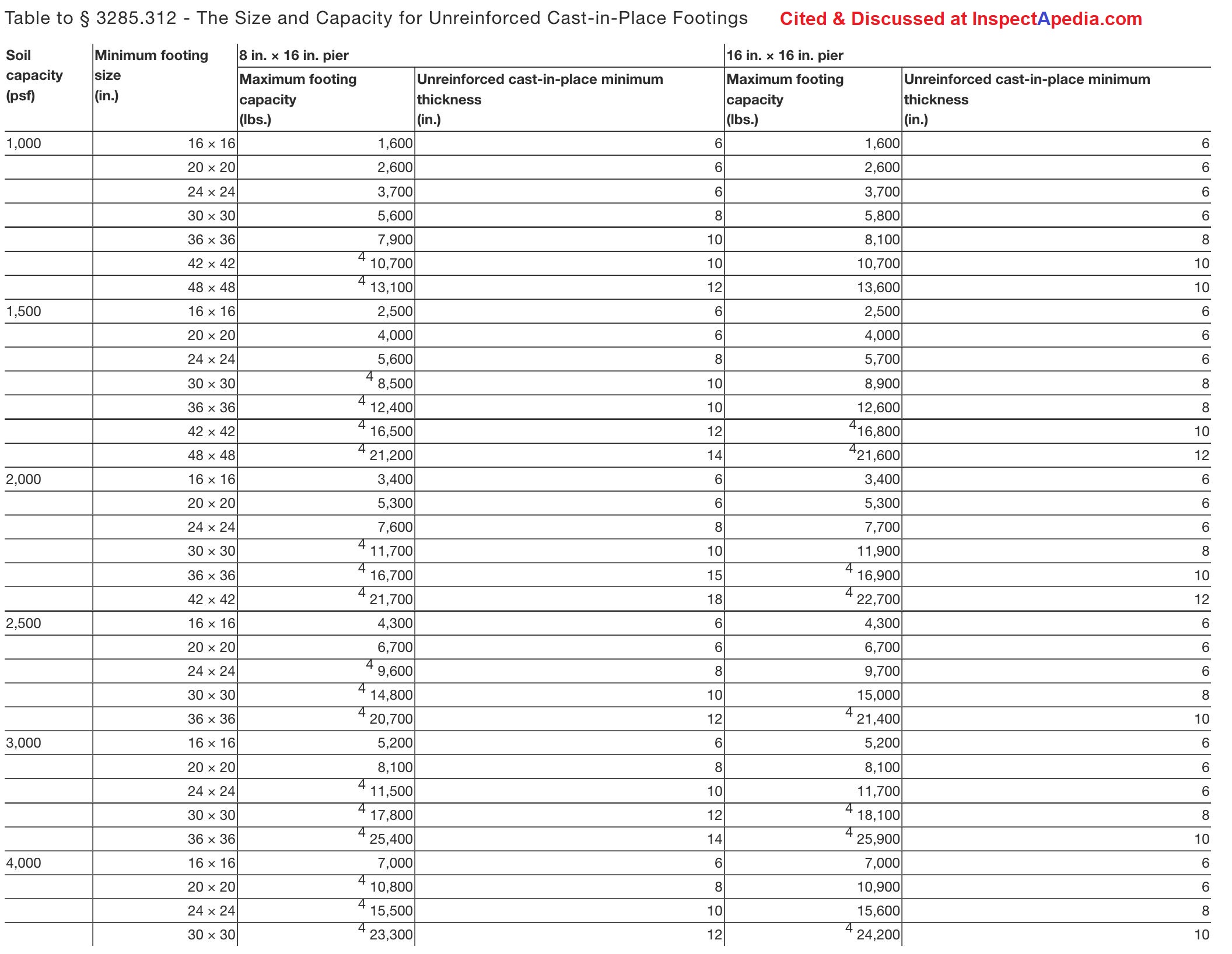
Notes to the table above
1. The footing sizes shown are for square pads and are based on the area (in. 2), shear and bending required for the loads shown.
Other configurations, such as rectangular or circular configurations, can be used, provided the area and depth is equal to or greater than the area and depth of the square footing shown in the table, and the distance from the edge of the pier to the edge of the footing is not less than the thickness of the footing.
2. The 6 in. cast-in-place values can be used for 4 in. unreinforced precast concrete footings.
3. The capacity values listed have been reduced by the dead load of the concrete footing.
4. Concrete block piers must not exceed their design capacity of 8,000 lbs. for 8″ × 16″ single stack block and 16,000 lbs. for 16″ × 16″ double stack block.
5. A registered professional engineer or registered architect must prepare the design, if the design loads exceed the capacity for single or double stack concrete block piers shown in footnote 4.
§ 3285.313 - Combination systems.
Support systems that combine both load-bearing capacity and uplift resistance must also be sized and designed for all applicable design loads.
§ 3285.314 - [Reserved]
§ 3285.315 - Special snow load conditions.
(a) General.
Foundations for homes designed for and located in areas with roof live loads greater than 40 psf must be designed by the manufacturer for the special snow load conditions, in accordance with acceptable engineering practice.
Where site or other conditions prohibit the use of the manufacturer's instructions, a registered professional engineer or registered architect must design the foundation for the special snow load conditions.
(b) Ramadas.
Ramadas may be used in areas with roof live loads greater than 40 psf. Ramadas are to be self-supporting, except that any connection to the home must be for weatherproofing only.
Mobile Home Foundation Codes & References
- HUD PERMANENT FOUNDATIONS GUIDE for MANUFACTURED HOUSING [PDF] (1996) Department of Housing and Urban Development (1996), source: https://www.huduser.gov/portal/publications/destech/permfound.html
This is the complete HUD foundation handbook in PDF format, compressed for faster downloading, no loss of data, no loss of image quality.
Abstract quoted from HUD
This handbook is a guide for those approving HUD-code manufactured homes on permanent foundations, including engineers, manufacturers, and site owners seeking approval.
It provides current technical information, recommendations, and tables of analytical data, expanding and clarifying the definition of a permanent foundation. It updates 1989 loading requirements for snow, wind, and seismic forces.
Because of the increased use of multi-section manufactured homes, the guide now includes consideration of large openings along the length of marriage walls in multi-section units.
The construction recommendations assure that the home, foundation, and site are all compatible. In addition to the new technical recommendations, the guide has been expanded and reorganized for easy reference with more illustrations and clarifications.
The handbook can greatly assist preparation of the worksheets needed to apply for an FHA mortgage - (HUD) TITLE 24, SUBTITLE B, CHAPTER XX, PART 3285 MODEL MANUFACTURED HOME INSTALLATION STANDARDS (2022) [PDF] - retrieved 2022/05/25, original source: https://www.ecfr.gov/current/title-24/subtitle-B/chapter-XX/part-3285
- Manufactured Housing Institute, OVERVIEW of MANUFACTURED HOME INSTALLATION [PDF] interprets the HUD code & document cited below. Manufactured Housing Institute http://www.manufacturedhousing.org e-mail: info@mfghome.org
- MANUFACTURED HOUSING RULES (TEXAS), [PDF] Effective: November 23, 2014, Administrative Rules of the Texas Department of Housing and Community Affairs 10 Texas Administrative Code, Chapter 80, retrieved 2017/06/09, original source: https://www.tdhca.state.tx.us/mh/docs/Rules-141123-160514.pdf
- Schult HOMES INSTALLATION MANUAL [PDF] from Clayton, original source https://origin-clayton-media.com/docs/installmanuals/Schult%20-%203-11.pdf
Watch out: see JACKING SAFETY PRECAUTIONS in the guide listed just above. - See MOBILE HOME CODES, STANDARDS & MANUALS for a complete list
Inspection Points for a manufactured home or mobile home pier foundation
Moved to MOBILE HOME PIER INSPECTION
STABILIZING SYSTEMS - Tie Downs for Mobile Homes
This topic has moved
to MOBILE HOME STABILIZING SYSTEMS
MULTI-WIDE CONNECTIONS - Multi-Wide Mobile Home unit connections:
This discussion has been moved to a new article found
at MOBILE HOME CONNECTIONS, MULTI-WIDE.
Version 3.6 - 04/25/07, updated through 05/2022 - Steve Vermilye, New Paltz NY and Daniel Friedman, Poughkeepsie NY, Hudson Valley ASHI Chapter Seminar, Newburgh NY, January 4, 2000, NY Metro ASHI Fall 99 Seminar, Holiday Inn Crowne Plaza, White Plains NY, October 2, 1999.
...
Reader Comments, Questions & Answers About The Article Above
Below you will find questions and answers previously posted on this page at its page bottom reader comment box.
Reader Q&A - also see RECOMMENDED ARTICLES & FAQs
On 2022-04-25 by L PHILLIPS - supporting piers under mobile home being undermined by rainwater
I live in a senior mobile home park and like the place and don't want to move, the owners attitude is, if you don't like something, get out.
Heavy rains cause water to wash out, undermine and pit the supports underneath. Now the floor isn't level anymore. Any suggestions?
On 2022-04-26 1 by Inspectapedia Com Moderator (mod) - heavy rains undermined mobile home piers: collapse warning!
@L PHILLIPS,
I sure do, I.P.
1. Watch out: your home could collapse or tip, causing injury or other unsafe conditions such as a broken gas line or sewer drain line.
So start by having an inspection of conditions under the home to see if it's safe.
2. Then the home needs to be jacked level and its support piers repaired, including adequate footings that won't tip or sink from surface runoff.
If you own the home that's your responsibility.
On 2021-12-08 by Serena - How do I find out how much weight each pier will hold?
How do I find out how much weight each pier will hold? I have 16 blocks, 8' apart on a 14x60 single wide that weighs 19,000 pounds.
How much weight can I add to the mobile? We need to re-roof it but need to add frame and I want to make sure the previous owner's renovations haven't brought me anywhere close to the max.
On 2021-12-08 by Inspectapedia Com Moderator (mod) - how much weight will each mobile home pier hold?
@Serena,
Fair question;
A real answer would require more data and engineering beyond my expertise.For single-stack concrete block mobile home pier loads,
Mobile home piers must be able to support loads up to 8,000 pounds. - 24 CFR 3285.307 - Perimeter support piers
Watch out: In general what's key isn't the load-bearing capacity of your piers - as just about any properly-constructed concrete block pier and footing can take tons more weight than your mobile home can possibly produce.
Rather the key points to attend are at least these:
- Do you have a pier below every support point specified by the mobile home manufacturer? The right number of piers?
- Are the piers of proper material, size, with footings, and connected to the structure?
- If you are adding weight to the home, how is that weight carried through the structure down to the piers?
- Are the structural connections properly made?
- and of course you could call the home's manufacturer customer support but I suspect they will duck when you ask about modifying their original home to add a roof
And example of a concern with some much-older mobile homes is that the original walls were framed with 1x3 or 2x3 lumber - and might need reinforcement if an owner is adding the weight of a gabled roof over the original home.
On 2021-11-28 by Karen S - concrete pad required below mobile home?
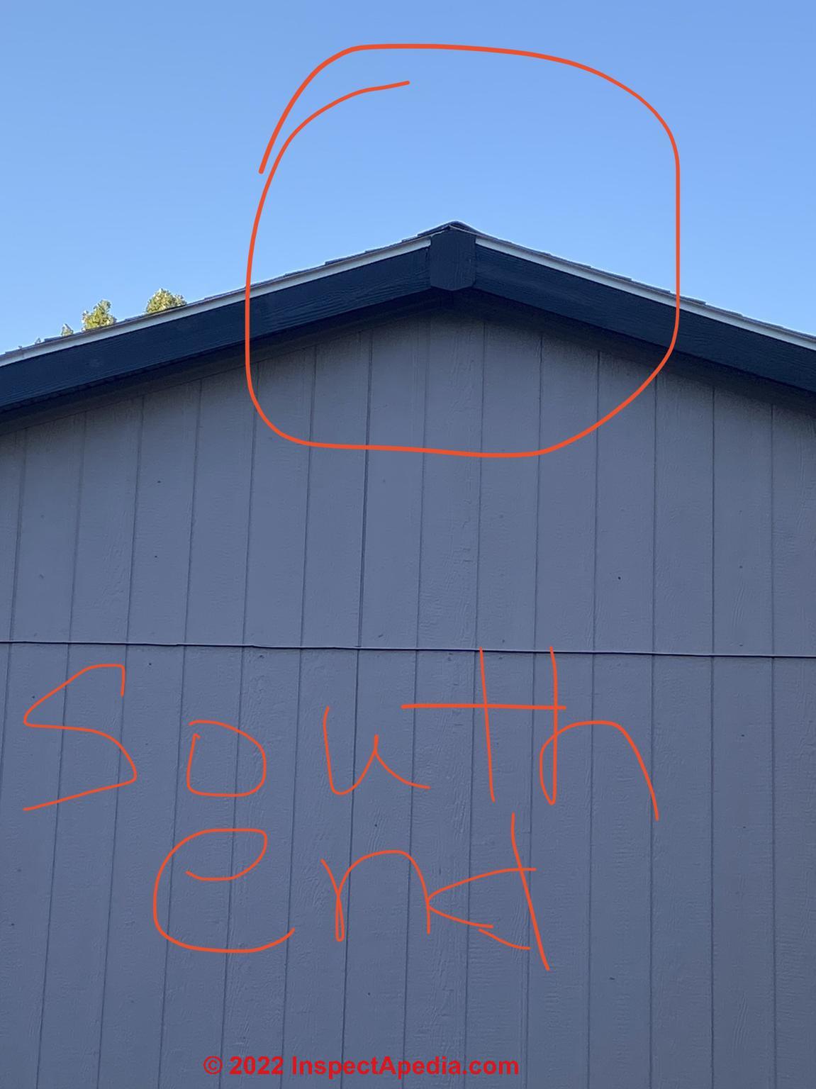
My 2010 Southern Energy Double wide in a mobile home community. Community owner refuses to do their legal responsibility of maintaining the lot grade and provide drainage, city snd state complaints are not addressed within a time range that prevents damage to home.
Attached photo shows how the separation is progressive since my new roof was installed , I keep paying to just have it jacked back up but that’s not correcting the issue, cannot find one contractor to come even look at it.
The pad is dirt it’s been in place for 11 years , natural erosion, no drainage , and measurements around the entire home is radically different. How do u find someone to come correct this issue , north end separation is not as bad as south end . .
[Photo below]
On 2021-11-28 by Inspectapedia Com Moderator (mod) - doublewide roof separation?
@Karen S,
First, I can't see any separation the roof in your photo. I think you're seeing original construction. Just consider that for the two sections of roof to have pulled-apart, you would also have to see separation or movement in the siding nailed over the gable-end of the home in your photo.
But we see no movement nor cracks nor damage in the siding.
About the requirement for a pad below mobile homes:
Depending on the country, city, and therefore local building codes, it's often permitted to site a mobile home over dirt instead of a concrete pad, BUT the home must be supported on properly-constructed, spaced, and structurally-connected piers.Your mobile home contractor or repair company can inspect the condition of your piers and provide proper ones where needed.
In your photo I see a gap in roof sheathing that may not indicate building movement; certainly this is a microscopic amount of information so we can't conclude the condition of your home, but one can note that if your home front and back sections had had actually separated by 6-inches or so (the gap), then the siding wouldn't be so intact as shown in the picture, and there would be gross cracking and movement evident indoors.
If you own the home, in most jurisdictions, the condition of its structure and piers are your responsibility. If you're a renter, that's usually the landlord's responsibility.
On 2021-06-19 16 by becky - cracks in the cinderblocks under our doublewide
I have been told we have cracks in about 10 cinder blocks under our doublewide. Our home is level. This was found when we were having part of the underbelly repaired. Should we be worried and have those blocks replaced? We had the doublewide since 2004
On 2021-06-19 by inspectapedia.com.moderator (mod) - cracks in cinder blocks supporting a mobile home
@becky,
That's a reasonable question but not one that I can answer from just your text. Perhaps you can attach a photo of a typical cracked concrete block pierr that is supporting your home.Critical would be to look for piers that are leaning, bulging, bowing, moving, or crushing.
On 2021-05-05 by Dianna - one end of our doublewide is 2" off the ground
I recently had a double wide moved the B side with kitchen baths and wash area buckled up in kitchen the end of the house is sitting about 2 inches off groun
On 2021-05-06 7 by danjoefriedman (mod) - mobile home support pier damage
@Dianna,
That sounds like a support pier problem under your home.
Your foundation or siting crew will need to determine whether the problem is that the footings under the piers were inadequate or if the piers simply need to be correctly adjusted.
On 2021-04-27 by Donald Edward jamieson - mobile home park manager says permanent footings under deck posts are not permitted?
Installation of a deck to my mobile home do it need footings. The park manager said there are not allowed they have to be mobile.
On 2021-04-27 by (mod) - does a mobile home deck need footings?
@Donald Edward jamieson,
Your local Building Code Compliance inspector is the final legal Authority on this point except that the mobile home park may have its own rules that extend the building code and would be legal provided they don't cause the building inspector to consider that they are a violation or unsafe.
What that means in a practical sense is that if you are mobile home park will not allow you to install permanent concrete footings for the posts for your deck you will need to rely on a simple ground-level concrete pad under your posts and then adequate diagonal or cross-bracing between them to assure that your deck structure is safe.
On 2021-03-22 by (mod) - jacking height 2-Inch limit when using metal piers under a mobile home
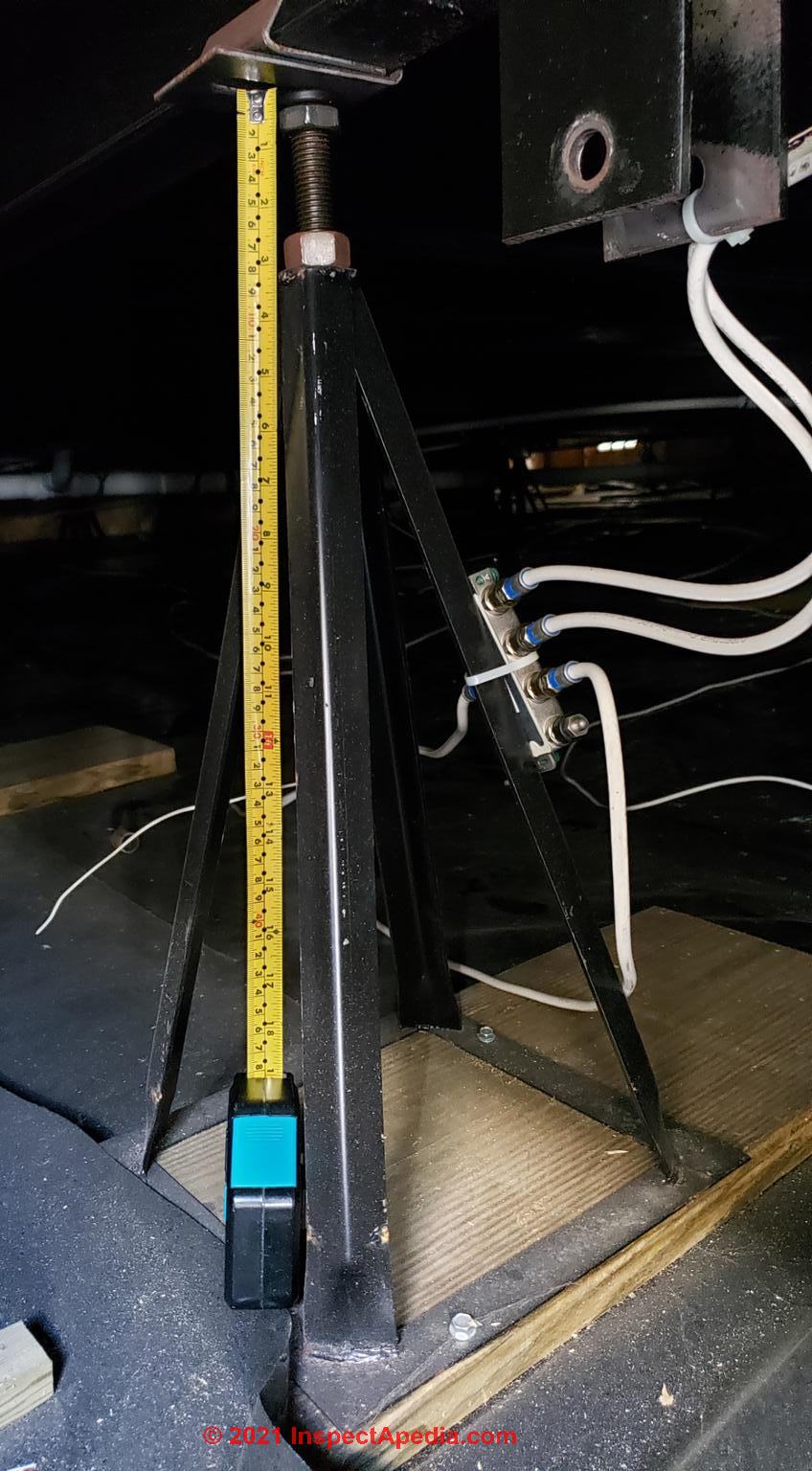 @Randall Dunn,
Interesting that you've got 2 1/2" of extension atop a roughly 24-inch jackstand (metal pier) so it's called out as a structural defect under HUD guidelines, but there may be more than one solution, as we'll discuss below..
[Click to enlarge any image]
The typical manufacturer's instructions for mobile home metal piers describes the adjustable height range as 1-2" so your inspector may be spot-on and also is consistent with mobile home codes as you have found and reported below.
The two-inch limit of screw-jack extension is usually measured from the upper surface of the pier or jackstand top plate to the underside of the screw jack's own top plate.
The authoritative answer is of course your local building code compliance inspector who is the final legal authority.
Also pertinent are what the home manufacturer's installation instructions say for both the jackstand total height, not just extension height.
Ask your building inspector if she would be happy if instead of buying 21 new metal piers or "jacks" for your home, instead you provided thicker solid masonry footings beneath each of the existing stands, sufficient to reduce the jacked-height to under 2-inches.
In any event, if you hired an installer to set your home, IMO that company is obligated to install the home properly and in compliance with building codes. So yes they'll want to correct the problem.
Questions About Steel Piers below a Mobile or Manufactured Home
On 2021-03-22 by Randall Dunn
Hello, I'm trying to find what the length of extension from the top of a manufactured home metal pyramid support pier is considered over extended? I'm being told that I need to replace 21 of the piers because they are overextended. I live in Santee, CA. Can you help me? Thanks for your time. Have a great day! Randall
On 2021-03-22 by (mod) - when is a screw-type support pier over-extended
@Randall Dunn,
Typical standards such as you'll see on this page set a limit of 1 1/2 to 2-inches of screw extension measured from the top of the pyramid's screw-opening to the top of the extendable screw, in an adjustable pier installation
Can you attach a photo of one of the most-extended piers, and give me the measurements.?
On 2021-03-22 by Randall Dunn - steel pier height requirements under mobile homes
Thanks for getting back to me. I may have already found my answer.
- [Photo above]
I've found:
6.2.3.2.4 Pier Heights.
6.2.3.2.4 Pier Heights. Manufactured pier heights shall be selected so that the adjustable risers do not extend more than 2 in. (50 mm) when finally positioned.
[This is found in HUD, MODEL MANUFACTURED HOME INSTALLATION STANDARDS [PDF] (2003) = Ed. ]
I've attached a photo of the one I could see from the entry to the underside of the home. It seems to be extended about 3" from the top of the pier.
There seems to be several inches still left on the riser bolt too.
Is this something I should be taking up with the installer to take care of?
Thanks for your time. Have a great day! Randall
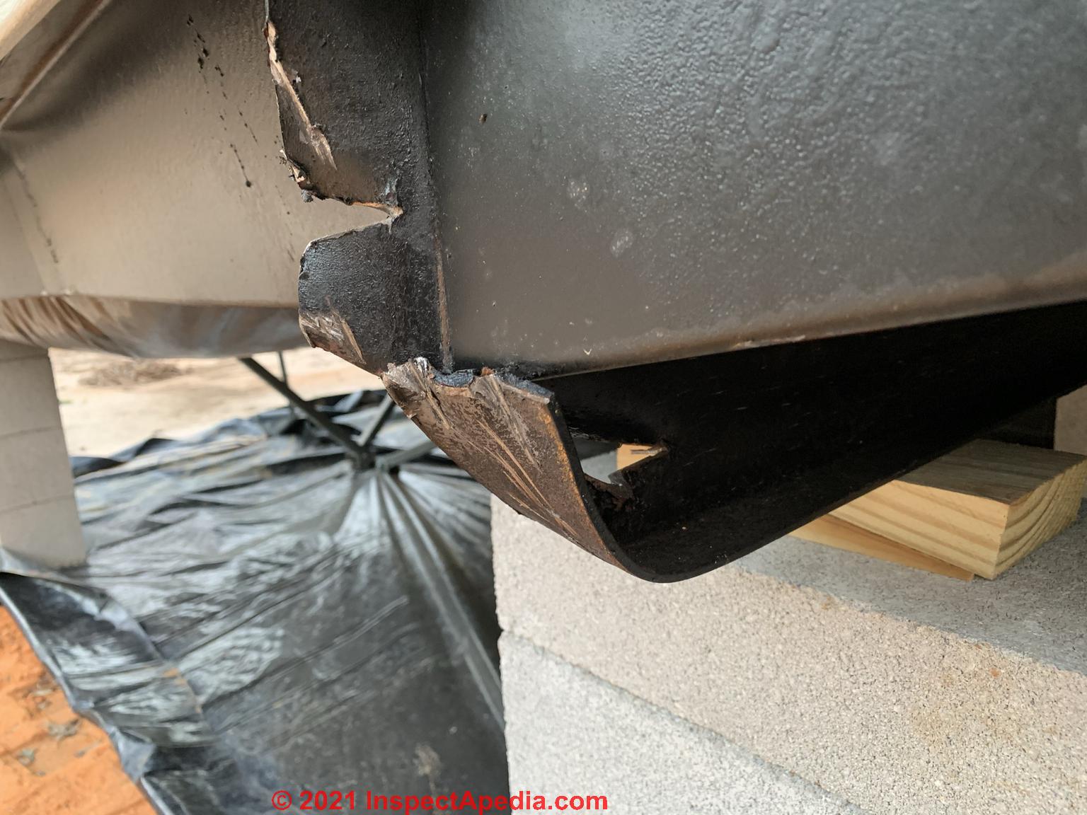
On 2021-03-22 by (mod) -
Watch out: I couldn't see a listing or label on your home's steel support piers. Do we know that these piers are rated (approved) and intended for permanent manufactured home support?
Watch out: if your mobile home steel piers are exposed to water and moisture there can be a more-serious longer-term safety hazard of rust and collapse of the whole stand.
also see the JACKING SAFETY PRECAUTIONS found in these example Schult HOMES INSTALLATION MANUAL [PDF] from Clayton, original source origin-clayton-media.com/docs/installmanuals/Schult%20-%203-11.pdf
where you'll see that for that case the manufacture specifically recommends using metal jacks ONLY for leveling and installing the home, and wants permanent masonry piers to be constructed.Watch out: Metal piers may not be approved for mobile home support in all jurisdictions.
On 2021-03-13 by Fran O'Neill - convert steel piers to concrete block?
If my new constructed double wide home is supported/stabilized by steel supports can i change this to concrete block? It is on a concrete foundation
On 2021-03-13 by (mod) - can I change steel support piers to concrete blocks?
@Fran O'Neill,
Check with your local building official, who is the final legal authority on the question of what support systems for your doublewide home will be permitted.
In general you could replace a steel lally column with a masonry support pier - both need to be on suitable footings or pads.
But
Watch out: a "stabilizing" system for a doublewide or singlewide mobile home may, depending on the wind zone rating where you live, require cables and anchors that can NOT be removed without both violating your local building codes and making your home unsafe.
On 2021-01-12 by Dudley - find weight bearing information for mobile home piers
We recently purchased a 1995 Liberty Mobile home and put a peaked metal roof on it. Now the county wants us to provide them weight bearing information for this mobile home. The weight of this metal roof is a lot less than a shingle roof would have been.
Since Liberty is no longer in business, where can I go to get this information or who can I contact to sign off that this mobile home can handle the weight.
On 2021-01-12 - by (mod) - county wants us to provide them weight bearing information for this mobile home
What a pain, Dudley.
What is the load bearing capacity of mobile home exterior walls?
What is the weight increase when converting a mobile home to use a pitched roof?
Someone is spending your money to reduce their risk - and a trivial risk at that, considering the point you make about relative weight- but let's get this clear: the weight of the roof on the walls of your mobile home is the sum of
- whatever original roof materials were left in place
- the new roof structure (trusses, rafters, whatever)
- the new roof covering (metal)
I agree that a metal roof is lighter than a shingle roof, but you'd want to argue that the weight of all of the roof materials is still safe for the home.
It's an ugly problem that means you'll need a design professional, like an architect or engineer who, for a fee, will look at your structure and write an "it's ok" letter - so I suspect at the very least you're looking at a fee to do that.See if you can find an RA or structural or civil engineer nearby who's familiar with mobile home construction and who is willing to look, or ask your building department in the county if they can recommend a design professional whose opinion they'll accept.
Basic mobile home roof weight bearing data:
A typical mobile home roof is built to carry a 30 pounds per square foot load, possibly varying by the snow zone where the home is sold.
In an area of average 2-3 ft deep snow loads, the mobile home roof will be built to carry 50 pounds per square foot.
In an area of deep snow, 5-6 ft, the roof would be built to carry up to 90 pounds per square foot.
The total weight of the roof includes both live and dead loads (live = snow, for example and dead = weight of the roof structure and covering) and that's what the home's walls will be designed to carry.
Typically a sloped roof on a new mobile home will have a roof slope of at least 4:12. Pitches range from 3:12 up to about 12:12 for some models.
Take a look at the framing for your mobile home's walls. If, for example, the walls are framed with 2x4s 16" on center, then their strength, assuming the framing components are fastened properly, will be similar to that of a stick-built house and your building department ought to be happy. But some older mobile homes may use smaller framing materials and their spacing may be different.
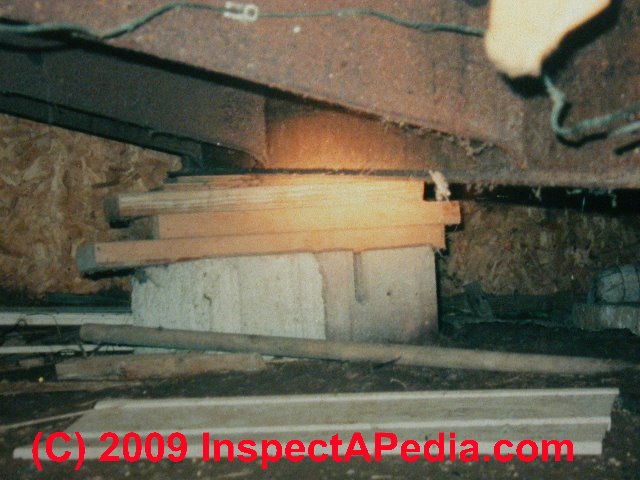
On 2020-11-13 by Mark: damaged steel chassis to mobile home
...
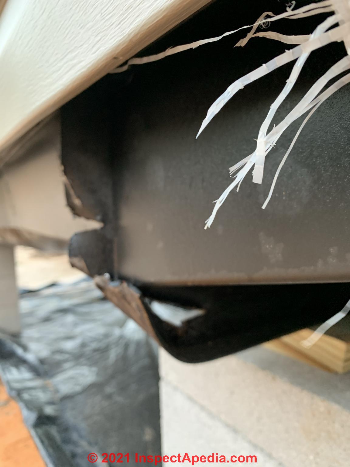
On 2020-11-13 - by (mod) - is this chassis damage or pier damage or both?
Mark:
I am guessing from your photos you're asking if we have a comment about the piers under your mobile home.
If you're asking about that bent metal strapping I don't know what to make of it. You'd want to know what that is and whether or not it is a broken weld and lost support or lost connection or if it's unimportant.
This home looks pretty new; identify the manufacturer and ask them what's required for both pier bearing point and connections of home to piers.
Also, depending on where you live, a tie-down system could be required to reduce the chances of the home blowing over in a storm.
I can't see all of the construction nor bearing points, but there is an interesting clue that raises a question: in the background of your photo I see black plastic that appears to extend under a stack of concrete blocks. Does that tell us that the home is supported on piers that are set on dirt without adequate footings?
On 2020-02-22 by Jack - mobile home singlewide pier footers in Kentucky
When a used mobile home single wide is set up in Kentucky what type of footers need to be under the blocks
On 2020-02-22 - by (mod) - what type of footers need to be under the blocks under mobile home piers
Jack:
Footings for mobile home piers:
Depending on soil conditions and climate a simple solid concrete pier is permitted in many local jurisdictions as the supporting base for a mobile home pier.
Local ordinances may vary but the basics of pier construction for mobile homes are at
MOBILE HOME PIERS inspectapedia.com/Manufactured_Homes/Mobile_Home_Support_Piers.php
Also see pier defects cited at
MOBILE HOME FOUNDATIONS
On 2019-09-24 by Brian - concrete blocks set on rubber pads in Ohio for mobile home piers
We live in a community and they are bringing in new homes and putting 3ft by 3ft rubber mates down then concrete blocks is that legal in ohio
On 2019-09-24 by (mod) - mobile home piers on rubber mats OK?
Brian
Basically yes if the soil and prep and drainage are adequate and proper.
Please see details of your question and a very detailed answer at
MOBILE HOME PIERS
...
Continue reading at MOBILE HOME STABILIZING SYSTEMS or select a topic from the closely-related articles below, or see the complete ARTICLE INDEX.
Or see MOBILE HOME PIER FAQs - questions & answers about piers under trailers & doublewides, posted originally at this page.
Or see these
Mobile Home Structure Articles
- MOBILE HOME CODES, STANDARDS & MANUALS
- MOBILE HOME STABILIZING SYSTEMS
- MOBILE HOME STRUCTURAL DEFECTS
- MOBILE HOME CONNECTIONS, MULTI-WIDE
- MOBILE HOME CRAWL SPACES
- MOBILE HOME ENERGY ZONES
- MOBILE HOME FOUNDATIONS
- MOBILE HOME PIERS
- MOBILE HOME PIER INSPECTION
- MOBILE HOME ROOF ZONES
- MOBILE HOME STABILIZING SYSTEMS
- MOBILE HOME WALL DEFECTS
- MOBILE HOME WIND RATINGS
- MOBILE HOME WIND RATINGS
Suggested citation for this web page
MOBILE HOME PIERS at InspectApedia.com - online encyclopedia of building & environmental inspection, testing, diagnosis, repair, & problem prevention advice.
Or see this
INDEX to RELATED ARTICLES: ARTICLE INDEX to MANUFACTURED & MOBILE HOMES
Or use the SEARCH BOX found below to Ask a Question or Search InspectApedia
Ask a Question or Search InspectApedia
Share this article:Try the search box just below, or if you prefer, post a question or comment in the Comments box below and we will respond promptly.
Search the InspectApedia website
Note: appearance of your Comment below may be delayed: if your comment contains an image, photograph, web link, or text that looks to the software as if it might be a web link, your posting will appear after it has been approved by a moderator. Apologies for the delay.
Only one image can be added per comment but you can post as many comments, and therefore images, as you like.
You will not receive a notification when a response to your question has been posted.
Please bookmark this page to make it easy for you to check back for our response.
IF above you see "Comment Form is loading comments..." then COMMENT BOX - countable.ca / bawkbox.com IS NOT WORKING.
In any case you are welcome to send an email directly to us at InspectApedia.com at editor@inspectApedia.com
We'll reply to you directly. Please help us help you by noting, in your email, the URL of the InspectApedia page where you wanted to comment.
Citations & References
In addition to any citations in the article above, a full list is available on request.
- [1] Section 184 Indian Home Loan Guarantee Program, U.S. Department of Housing & Urban Development, web search 1/5/2012, original source: portal.hud.gov/hudportal/HUD?src=/program_offices/public_indian_housing/ih/homeownership/184 - Quoting:
The Section 184 Indian Home Loan Guarantee Program is a home mortgage specifically designed for American Indian and Alaska Native families, Alaska Villages, Tribes, or Tribally Designated Housing Entities. Section 184 loans can be used, both on and off native lands, for new construction, rehabilitation, purchase of an existing home, or refinance.
Also see Freddie Mac & Fannie Mae - [2] Native American Housing Loan Guarantee Program HUD Section 184 Loans At A Glance, FannieMae, web search 1/5/12, original source: efanniemae.com/sf/mortgageproducts/pdf/section184aag.pdf
- [5] "Modular Home Construction, special defects and inspection methods" Dan Friedman, NY Metro ASHI Seminar, Holiday Inn, Crowne Plaza, White Plains NY, October 4, 1996
- [9] New York State: "Manufactured Homes: an installation guide for the code enforcement official," undated. [Div. of Code Enforcement & Admin. - 518-474-4073, George E. Clark, Jr., Director] - this is a guide tool, not an enforcement code or standard.
- [10] HUD State Administrative Agency (for 36 states) (NY: 518-474-4073) - for complaints
- [11] Manufactured Housing Institute, 2101 Wilson Blvd. Ste. 610, Arlington VA 22201 703-558-0400 Web: mfghome.org
- [12] NYMHA, 35 Commerce Ave., Albany NY 12206-2015 518-435-9859 800-721-HOME (they want the Star Program to provide for separate assessment of manufactured homes)
- [13] Consumer Reports: www.consumerreports.org - special report 2/98
- [14] Mobile Home Inspection Checklist, Florida, Town of Lady Lake Building Department
- [15] Thanks to home inspector Peter Bennett for eagle-eye editing assistance regarding spelling at this web article series. Little Silver, NJ 07739 Office 732-758-9887 Fax 732-758-8993 Cell 732-245-9817 afullhouseinspectionco@gmail.com
- Our recommended books about building & mechanical systems design, inspection, problem diagnosis, and repair, and about indoor environment and IAQ testing, diagnosis, and cleanup are at the InspectAPedia Bookstore. Also see our Book Reviews - InspectAPedia.
- CRAWL SPACE MOISTURE CONTROL [PDF] U.S. Department of Energy
- Domestic Building Surveys, Andrew R. Williams, Kindle book, Amazon.com
- Defects and Deterioration in Buildings: A Practical Guide to the Science and Technology of Material Failure, Barry Richardson, Spon Press; 2d Ed (2001), ISBN-10: 041925210X, ISBN-13: 978-0419252108. Quoting:
A professional reference designed to assist surveyors, engineers, architects and contractors in diagnosing existing problems and avoiding them in new buildings. Fully revised and updated, this edition, in new clearer format, covers developments in building defects, and problems such as sick building syndrome. Well liked for its mixture of theory and practice the new edition will complement Hinks and Cook's student textbook on defects at the practitioner level. - MOISTURE CONTROL in BUILDINGS [PDF] U.S. Department of Energy
- MOISTURE CONTROL in WALLS [PDF] U.S. Department of Energy
- In addition to citations & references found in this article, see the research citations given at the end of the related articles found at our suggested
CONTINUE READING or RECOMMENDED ARTICLES.
- Carson, Dunlop & Associates Ltd., 120 Carlton Street Suite 407, Toronto ON M5A 4K2. Tel: (416) 964-9415 1-800-268-7070 Email: info@carsondunlop.com. Alan Carson is a past president of ASHI, the American Society of Home Inspectors.
Thanks to Alan Carson and Bob Dunlop, for permission for InspectAPedia to use text excerpts from The HOME REFERENCE BOOK - the Encyclopedia of Homes and to use illustrations from The ILLUSTRATED HOME .
Carson Dunlop Associates provides extensive home inspection education and report writing material. In gratitude we provide links to tsome Carson Dunlop Associates products and services.
 |
HOME | ABOUT | ASK a QUESTION | CONTACT | CONTENT USE POLICY | DESCRIPTION | POLICIES | PRIVACY | |
| © 2026 - 1985 Publisher InspectApedia.com - Daniel Friedman | |||||||||