
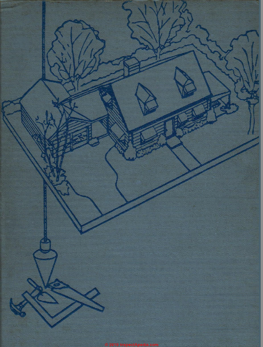
 Framing the House
Chapter 8 of How to Build Your Dream Home © 2020 InspectApedia.com

- POST a QUESTION or COMMENT about how to identify the architectural style of buildings and building components
Framing: how to frame up an owner-built home.
This article series provides an updated version of Hubbard Cobb's Your Dream Home, illustrated by Sigman-Ward, first published by Wm. H. Wise & Co. New York, 1950.
From site selection and obtaining financing through each step in construction of a single family home the simple procedures and drawings in this book are still useful for anyone building or repairing a home or other small structure.
InspectAPedia tolerates no conflicts of interest. We have no relationship with advertisers, products, or services discussed at this website.
- Daniel Friedman, Publisher/Editor/Author - See WHO ARE WE?
Framing the House: for DIY Builders
 This is Chapter 8 of BUILD YOUR DREAM HOME at InspectApedia.com - online encyclopedia of building & environmental inspection, testing, diagnosis, repair, & problem prevention advice.
This web page is also available as FRAMING THE HOUSE [eBook], or as a PDF image at FRAMING THE HOUSE [PDF] original page images.
The job of framing the house consists of a number of operations.
They are covered under the following main headings in the order given: Sills, joists, floor openings, bridging, sub-flooring, walls, breezeway and garage, sheathing, openings for doors and windows, ceiling joists, and roof.
Chapter Contents
- FRAMING THE SILLS, RIM JOIST, WALLS
- FRAMING a GARAGE & BREEZEWAY
- SHEATHING WALLS
- FRAMING DOOR & WINDOW OPENINGS
- SCAFFOLDING TIPS
- FRAMING CEILING JOISTS
- FRAMING THE ROOF
- FRAMING DORMER WINDOWS
- ROOF SHEATHING
- GUTTERS
- ROOF COVERING CHOICES
- MATERIALS LIST FOR THE OWNER-BUILT HOUSE
How to Frame the Sills, Rim Joist, Walls, Floor Openings
Choosing the Sill Width
There is a choice of several different types of sill that can be used. For all types of foundation, except piers and posts, the sill need not be of heavy timber—2" x 6" or 2" x 8" is quite suitable.
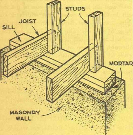
Fig. 1. Type of sill used for balloon framing.
[Click to enlarge any image]
In sections of the country subject to heavy winds, a 4" [nominal thickness, thus 3 1/2" thick in common lumber sizes - Ed.] sill is often used as this affords a greater nailing surface for the diagonal sheathing and therefore increases the over-all strength of the building to withstand the heavier strains to be expected.
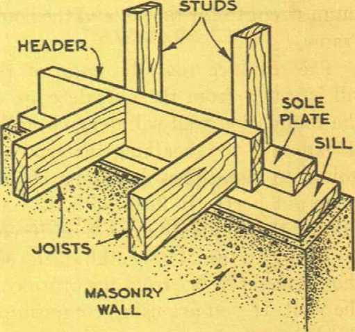
Fig. 2. Construction of the T sill, a type frequently used.
Figs. 1, 2 and 3 show three types of sill that are in common use today. Each one has advantages and disadvantages, but in the long run, one is probably just as good as the other. When it comes to framing a house, probably no two builders will frame in quite the same manner, and for each method there will be critics as well as champions.
For our purpose the box sill shown in Fig. 3 is perfectly adequate and so we shall follow through with this type.
The sill itself is a 2" x 6" No. 1 Common grade lumber. It is set in a thin bed of mortar and anchored to the foundation wall by means of the anchor bolts that were set in the masonry during its construction. The sill is joined at the comers with a simple half-lap joint, and this should be cut and fitted with care to provide maximum strength for the sill and the house frame.
The distance that the edge of the sill is set in from the outside edge of the foundation wall will depend on the thickness of the sheathing that you are going to use. The sheathing should come out perfectly flush with the outside of the foundation wall, so if you are going to use 3/4" sheathing, the sill should be set in 3/4" from the outside of the wall. If you are using composition sheathing, find out how thick it is and then place the sill this same distance in from the outside of the foundation wall.
Allow time for the mortar to harden, larities in the wall surface. Once the slip washers over the ends of the anchor sill is in place, check it with a level, bolts and then run down the nuts.
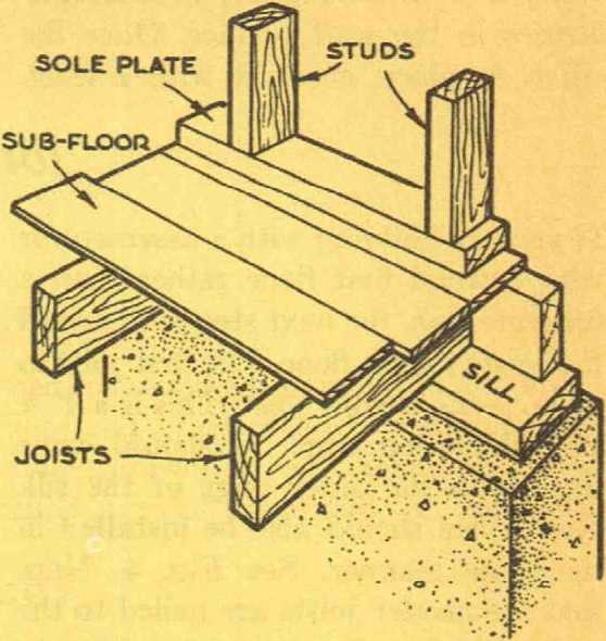
Fig. 3. Detail of box sill construction. The 2"x6" sill is anchored to the top of the foundation wall by means of anchor bolts. Note the thin bed of mortar between the sill and the foundation wall. This not only makes a tight seam between wall and sill but also helps you to get the sill level.
The header joist which is on edge comes out flush with the outside edge of the sill. The floor joists are toe-nailed to the sill and nails are driven through the face of the header into the ends of the floor joists. The sub-flooring is then laid, and over this goes the sole to which the wall studding is attached.
Holes should be drilled in the sill for the anchor bolts and the sill should be given a coat of white-lead paint to prevent decay. The mortar used for bedding the sill to the foundation wall is 1 part cement to 3 parts sand. It will not only make a good tight joint between the top of the wall and the sill, but will also enable you to get the sill to sit perfectly level in spite of any little irregu-
How to Frame the Rim Joists or Header Joists
If you are building with a basement or with a wood first floor rather than a concrete slab, the next step is to install the joists for the floor. The first joist to go on is the header joist. This is a 2" x 10" placed on edge.
It should come flush with the outer edge of the sill. End joists should also be installed in the same manner. See Fig. 4. Note that the header joists are nailed to the end joists as well as being toe-nailed to the sill.
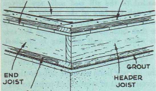
Fig. 4. Detail showing the relationship between the sill, the header joist, the joists and the sole plate.
Twenty-penny nails are used to secure the header to the end joists. Ten-penny nails are sufficient to tie the header and end joists to the sill. If diagonal sheathing is to be used, the joists need be secured to the sill only with a sufficient number of nails to hold them erect, because the sheathing will tie both sill, header and end joists together.
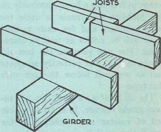
Fig. 5. How the floor joists rest on the girder. The joist should overlap the width of the girder and can be nailed together and then toe-nailed to the girder.
The floor joists required are also 2" x 10". These are placed on edge and are spaced 16" on center. If the joists are not perfectly level, that is, if they have a slight crown or high point, the high point should face up. The joists will run between the sill and the girder that runs down the approximate center of the house. If a steel girder is used, it is necessary to fasten a 2" x 4" to it by means of clinched nails or lag screws so that there will be something to which the joists can be spiked. This 2" x 4" should be flush with the sill so that the joists will be level.
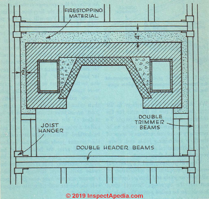
Fig. 6. Correct method of framing around the fireplace opening. Note that trimmers and headers are doubled. A cantilever is installed at one side of the opening to support the flooring over that portion of opening not covered by fireplace hearth.
If you decide to use a steel girder, be careful to allow for the 2" x 4" when you are figuring the dimensions of the pocket in the foundation wall in which the girder is eventually going to rest.
Fig. 5 shows how the joists bear on the girder. The joists are nailed together with two 10c? nails and then toe-nailed to the girder with one 10d nail on each side of the two joists.
How to Frame Floor Openings
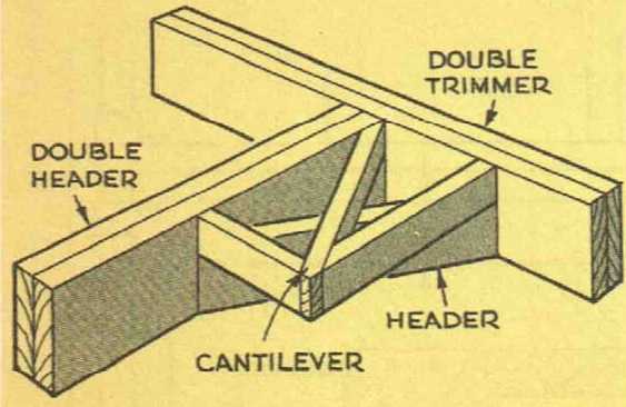
Fig. 7. Detail of cantilever arrangement for framework around the fireplace opening in the floor.
We will require two openings in the first floor and two in the attic for the chimney and stairs to pass through. To make these openings it is going to be necessary to cut out sections of some of the floor and ceiling joists and, therefore, additional reinforcements will be required around these points.
You will probably find it a good deal easier to complete the installation of all the floor joists and then go back and cut out the openings. Several stout boards can be nailed across the ends of the joists that are to be cut out so that they will stay in place while they are being cut and until the necessary arrangements can be made to hold them solid.
Consult the framing plans for the location of the openings in the first and second floor for the fireplace, chimney and stair well. You will note that the joists that frame these openings are double. The joists that have been cut are called tail beams. The cut end is supported by a header, which in turn is supported by the double joists on each side of the opening. The header is double and is of the same stock as the regular joists, 2" x 10".
You may find that, due to the manner in which the joists were spaced, there is no regular joist on one side of the opening. Rather than extend the header to the nearest joist, an additional one should be installed at the proper point. This is called a trimmer joist and should also be doubled. To insure adequate nailing, the trimmer joists should not be doubled until after the header joist has been put into place and nailed to the single trimmers. This is necessary because nails driven through a double trimmer are not long enough to provide the header with adequate support. See Fig. 6.
A special type of framing, called a cantilever, is sometimes required on one side of the fireplace opening, since this area will not alwavs be covered bv the hearth. See Fig. 7.
Cross Bridging Between Joists Stiffens the Floor
Cross bridging is made up of strips of form an X. See Fig. 8. Bridging serves wood nailed between the floor joists to two very important purposes. First, it tends to stiffen the joists and, therefore, the floor as well.
Second, it helps to distribute the load on the floor among several joists. In cheap construction, the bridging is often left out because it requires a good deal of time and work to install. This is false economy since a floor without bridging is almost sure to be weak.
Bridging is required for every eight feet of joists. This means, in our particular case, that a set of bridging is required on each side of the girder. It should be located in the approximate center of the joists on each side.
Bridging can be made out of rough 1" x 3" No. 2 Common grade. If you have some wider or heavier stock that is going to waste, it can be used, too. If you want to save some time and spend some extra money, metal bridging is available and, in addition, is very easily installed.
The best and quickest way to cut the bridging is to cut the first piece by hand according to the necessary measurements and then make a miter box so that the rest can be cut on this pattern. Be sure that the first piece of bridging that is to serve as a pattern is correctly cut.
Most of the benefit of bridging will be lost if the pieces do not fit correctly between the joists.
Run a chalk line across the joists at the point where the bridging is to be placed. If 1" x 3" stock is used, the bridging should be nailed at each end with two 8d nails. Sight down the joist before nailing to be sure that it is sitting correctly. If it is not, push it upright.
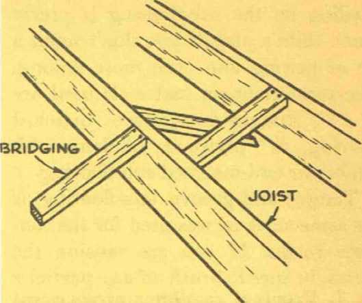
Fig. 8. Bridging between the floor and ceiling joists can be of wood or metal. The bottom ends of the bridging are nailed in place after the sub-floor has been laid.
At the present time, only the top of the bridging is nailed to the joists. The lower end will be left free imtil the sub-floor is in place. The reason for this is that when the sub-floor is installed, it will tend to pull the joists into correct alignment. If the bridging is nailed before the sub-floor is installed, the sub-floor will not be able to correct the position of the joists. It is wise, however, to start the two nails in the bottom of each piece of bridging before the sub-floor goes down.
This will save a lot of time later on and is of special value when there is no basement and you have to tack the lower ends of the bridging to the joists from the cramped position that crawl space affords.
Install the Sub-Flooring
Nailing on the sub-flooring is pretty much child’s play if you don’t mind a lot of sawing and even more nailing. The most common materials used are l" x 6" tongue-and-groove matched flooring, 5/8" plywood, random-width lumber or end-matched sub-flooring.
Tongue-and-groove sub-flooring is the same stock as was used for the concrete forms. If you are reusing the forms, be sure to brush off any particles of concrete that are still clinging to the wood. The sub-flooring can be laid either diagonally or at right angles to the floor joists. The best method is to run the flooring diagonally, because this will allow you to lay the finished floor in any direction you choose. The boards should be nailed at each point where they cross a joist with two 8d nails. If you use boards that are wider than 6" use three 8d nails. See Fig. 9.
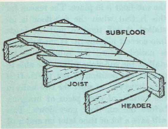
Fig. 9. How to apply diagonal sub-flooring. Note that the end joint between two of the boards is centered over a joist so that there will he no chance of these boards cracking.
Some authorities feel that if tongue-and-groove lumber is used, the end joints between pieces do not have to come over joists. There is, however, some difference of opinion on this matter, so perhaps it is best to play safe and have the end joints come over joists.
Sheets of ph^wood should be nailed with 8d nails spaced every 6" along all edges and 12" along the inside joists. The grain of the face ply should run at right angles to the joists.
Random-width lumber is about the least expensive material you can use for sub-floors. It has square edges and is nailed in the same manner as tongue-and-groove. All end joints must come over joists. Random-width lumber will run all the way from 4" to 12". Of all the materials, it requires the most time to install.
End-matched sub-flooring is rather expensive, but it is a great time saver because the end joints do not have to come over joists. The only sawing required is to cut off the end of the board that extends beyond the floor. It should be nailed in the same manner as tongue-and-groove, and it is important to nail it wherever it crosses a joist near the end of each board.
The sub-flooring should be tight all over and come flush with the outside edge of the headers and end-joists. If you use tongue-and-groove or random-width stock and lay it diagonally, be sure to cut the ends on an angle so that the entire joint between two abutting go underneath and nail on the lower ends will come over a joist for nailing, ends of the bridging, which were left As soon as the sub-floor is in place, loose until the sub-floor was in place.
How to Frame the Walls
Study Fig. 10 and you will see that the wall framework is based on a 2" x 4" sole plate that is nailed through the sub-floor into the joists. This serves as a nailing base for the bottoms of the 2" x 4" vertical studding. The top of the studding is tied together with a top plate made of two 2" x 4"’s.
There are several methods you can use to erect the frame of the house, but the best method is to make up complete units of the wall on the ground and then hoist them into position. This method is not only quicker than the others but you get a stronger wall section, because the ends of the studs are fastened to the sole plate with nails driven right through the plate rather than being toe-nailed into it from the sides of the studs.
The Studs
But regardless of which method of framing is used, the first job is to cut all the studding to the right length. You can save a good deal of time right here by marking out a master stud-pattern on the sub-floor and then using this to cut groups of studs to the correct size rather than measuring and cutting one stud at a time. See Fig. 11. It is important that all the studs be of equal length.
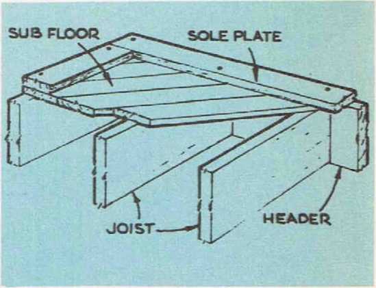
Fig. 10. The sole plate should be nailed through the sub-flooring into the joists and the header joist.
You will need approximately 110 studs for the wall framework and main bearing-partition of the house. They should be 7'3" in length.
Corner Posts
When the studs have been cut to length, go to work and build four corner posts. As far as the load that they must carry goes, the corner posts are no different from the rest of the studding and one 2" x 4'" would be adequate, but this would not provide any nailing surface for the interior wall lath or wallboard.
Fig. 12 shows a very efficient type of comer post that is easily constructed out of ordinary 2" x 4"s and provides the necessary nailing surfaces for the inside wall materials.
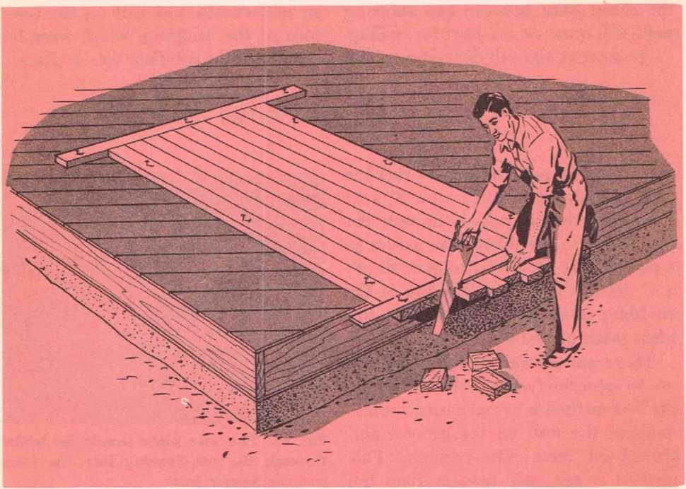
Fig. 11. A simple jig of this sort laid out ding to size. You’ll also find that it is easier on the sub-floor will save a good deal of to get all studs the same length than if you time when it comes to cutting the wall stud- measure and cut each individually.
Note that the middle stud is pulled out for about one-half its width to provide one of the nailing surfaces. The only drawback to this type of post is that one edge measures 3 5/8", which is the width of the wide side of a dressed 2" x 4", while the other nailing edge of the post is only 3 1/4". This means that the difference between the two thicknesses will have to be taken care of by nailing furring strips to the 3 1/4" edge to bring it out to 3 5/8".
If you have some 4" x 4" stock around, this can be used for the posts, but you will have to tack strips of 1" x 2" to the edges to provide the necessary nailing surfaces. Fig. 13 shows another method of constructing a corner post out of 2" x 4"’s.
Sole Plate and Top Plate
The next step in making up a section of wall on the ground is to lay a 2" x 4" sole plate along the edge of the sub-floor. Make this extend flush with one corner and then nail it lightly in place so that it will not move out of position. Next, lay a 2" x 4" top plate alongside it. Now what we want to do is measure off on both sole and top plate the location of each piece of studding. Studding should be spaced 16" on center.
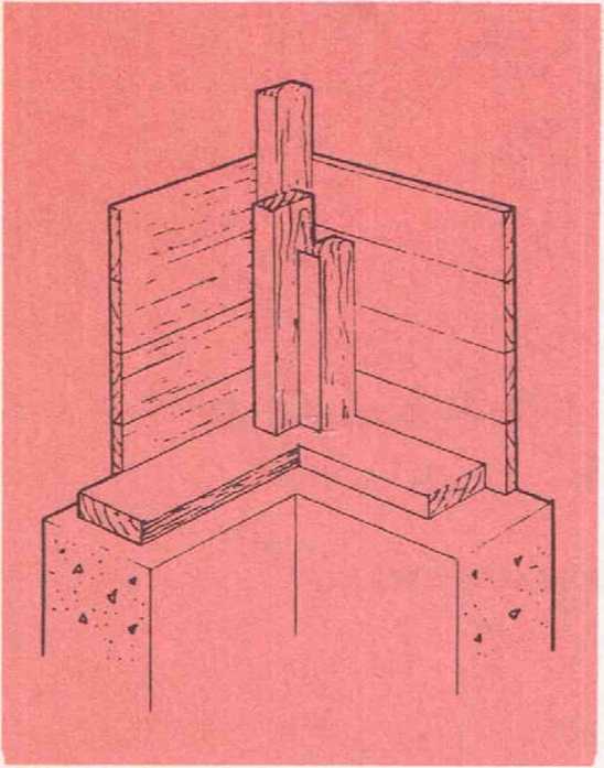
Fig. 12. A very satisfactory type of corner post built out of 2"x4",s. Note that the center stud is pulled out for about one-half its width so that there will be a nailing surface for the lath or wallboard at the inside corners.
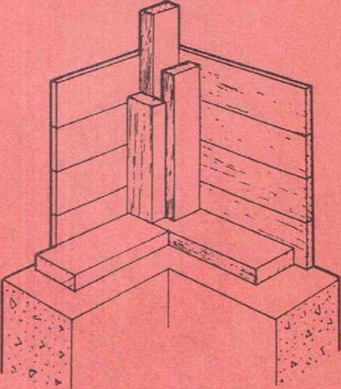
Fig. 13. This type of comer post is also suitable but is somewhat more difficult to construct than the one shown in Fig. 12.
Be sure that these measurements are accurate. This is important, not because it would make anv difference in the strength of your house if the studs were not spaced quite 16" on center, but because the materials that are to follow—the insulation, wall lath, wall-board, etc.—are all cut to fit studding spaced either 16" or 24" on center.
If you don’t get the studding positioned properly, you are going to waste a lot of time later on tacking strips of wood to studs so that you can fasten on insulation or wallboard. Studding is often spaced 24" on center, but this will not provide as rigid a frame as when it is spaced 16".
Start measuring off the 16" intervals from the corner. Remember, however, that the corner post is wider than the other wall studs, so make your first measurement not from the middle of the corner post but from the middle of the nailing surface.
As neither the sole nor top plate will extend the entire length of a wall in one solid piece, their joints must come over a piece of studding. Therefore, cut sections of both sole and top plates off so that they are of equal length and the cut ends come in the middle of a piece of studding. As you mark off the location of the studding on both the top and sole plate, be sure that you indicate with an X on which side of the marked line the studding is to go.
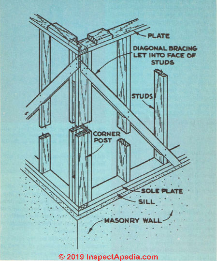
Fig. 14. The method used to install let-in bracing and the top plate. Note that the framework has been notched out from the corner post to the sill so that the brace will provide maximum support. The brace is nailed to each piece of the framework. The joint between the lower top plate and the upper top plate is staggered in order that the corner post will be tied into the studding.
At this time do not bother to make any openings in either the studding or the sole plate for windows or doors. What wc shall do is make up the entire wall framework and then go back and cut out the necessary openings. This may sound like a waste of both time and lumber. Actually it is not. You will find it much easier and quicker to frame the walls without making allowance for these openings, and cutting them out later on will not take much time. The lumber that is removed can be reused to double the framework around the openings.
Installation of Wall Studs
Once you have a section of sole and top plates measured off and cut, nail the studding between them. The corner post should be installed as well as the regular studding. The studding is fastened to both sole and top plates with two 16d nails driven up through the sole and down through the top plate into the studding. As soon as the section has been completed, tack some braces across it so that it will be more or less rigid and hoist it into position. The sole plate should be flush with the outside edge of the sill. See Fig. 14.
Use temporary braces to hold the section of wall in position while you plumb it to be sure that it is straight up and down. Once you get it right, provide additional braces to hold it there until the entire house has been framed.
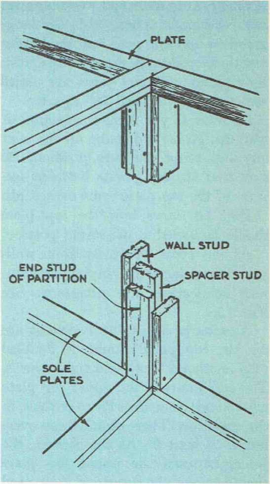
Fig. 15. Detail showing how a partition is joined to a wall. The upper part of the partition plate is nailed through into the lower part of the wall plate. A spacer stud is inserted between the wall studs to provide a nailing base for the partition stud at the end.
Much time can be wasted by getting a section of wall plumb and then having it knocked out of plumb because it was not sufficiently braced.
Once you have the section plumb, nail the sole plate down. The sole plate resting over headers and joists is nailed with 16d nails. These nails are staggered so that one goes into the header and the next into the regular floor joist. Sole plates over end joists are nailed with 16d nails spaced 16" apart.
As soon as you have one section of wall up, go on and make up the next one and bring this into position. Be sure that the end joints between sections of the top plate come over studs.
Fig. 14 shows how the top plate should be nailed to the corner posts.
At the point where partition walls join the outside walls, special partition-wall connections are necessary. See Fig. 15.
As soon as all the wall sections are up, the top plate should be doubled with another 2" x 4" laid right over it. The end joints in the upper top plate must never come directlv over those in the one below. There should be an overlap of at least 2'. At the corners, the joints between the upper top plate should he just the reverse of those used for the lower top plate. The top plate is nailed to the lower plate with 10d nails spaced 16" apart. See Fig. 14.
Other Methods of Wall Framing
Another method of framing the walls is to nail down the sole plate and then place the top plate alongside it so that the two can be measured for studding. Then nail the tops of the studding to the top plate, brace this framework and lift it into position. When the section has been plumbed and braced, the ends of the studding can be nailed to the sole plate with two 8d nails in each of the wide faces of the studs.
You will find that a block of wood nailed to the sole plate with one edge up against the stud will hold the stud in position so that it will not move when the nails are driven down. After the wall sections are up, the upper top plate is fastened on in just the same way as previously described.
Another method—and by far the slowest—is to frame the walls one piece at a time. The sole plate is nailed down and then the corner posts are placed on it, plumbed and toe-nailed down. The posts should be braced on both sides. Next, several pieces of studding are put up and braced into the correct alignment. When this has been done, the top plate is put on. Now the rest of the studding is put into position.
Bracing the Walls
Once the outside walls have been framed and checked to be sure that they are plumb, they should be permanently braced. Many experts feel that if either plywood or diagonal sheathing is used over the framework, no additional bracing is required. However, if horizontal sheathing or composition sheathing is going to be used, bracing is absolutely necessary for a strong solid building.
The material used for the braces does not have to be heavv stock, 1" x 4" is perfectly adequate. It is the manner in which this type of brace is installed that provides the strength. The most effective type of brace is a 1" x 4" run from
the top of a corner post down across several pieces of studding and into the sole plate. Each member of the framework that the brace crosses is cut out with a chisel so that the brace can be recessed into the member. This not only provides a flush surface for the sheathing to be nailed over but it also increases the strength of the brace many times over.
A board just nailed across the studding does not provide any great amount of strength. The let-in brace is nailed to the sole plate and the corner post with three lOd nails. Where it crosses studding, it is nailed with two 10d nails. It is important that you cut the recesses for the brace as accurately as possible, because if they are too large, you will not get the same value from the brace as when it fits snugly into the recesses. See Fig. 14.
As soon as the four outside walls have been framed, frame the main bearing partition. See Fig. 15. This consists of the same materials as used for the outside walls. A sole plate is nailed through the sub-floor into the girder. Studding is spaced 16" on center and the openings for doors and so on can be cut out later on.
Framing For House With Concrete Slab Floor
The same framing methods will apply to this type of house as to the one with a wood floor on wood joists.
The only difference is, of course, that the framework is built up from a 2" x 4" sill anchored to the foundation wall.
See Fig. 21 in Chapter 7.
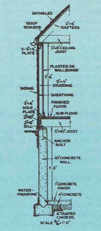
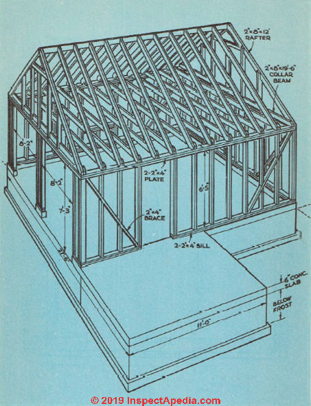
Above: Section View of House and Foundation
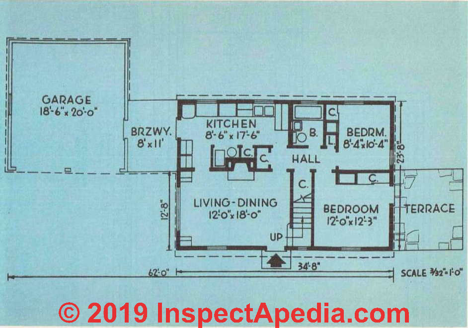
Above: General Floor Plan of House, Garage and Breezeway
Building the Breezeway & Garage
The floor of the breezeway should be one step below the finish-floor level of the house, and the floor of the garage one step below the breezeway floor.
Garage Foundations and Floors
Footings for the breezeway and garage should extend below the local frost line and should be 6" deep and 12" wide. The foundations for both should be 6" thick.
The floor of the breezeway should be a slab of concrete 6" thick. It is poured over a solid base of cinders or gravel. The floor of the garage should be set 6" below the top of the garage foundation and can be either poured concrete or earth. There should be expansion joints between the breezeway floor and the house and garage foundations, and also an expansion joint between the concrete garage floor, if one is used, and the surrounding foundations.
Anchor bolts must be installed in the top of the garage foundation so that the sills can be attached in place.
Framing the Garage
The best method of building the breezeway and garage unit is to construct the garage first. Study the framing plans for the garage carefully. Note that the sill consists of two 2" x 4"s and that there are two sets of double 2" x 4"s at each side of the front opening as well as a double set in the middle of the opening.
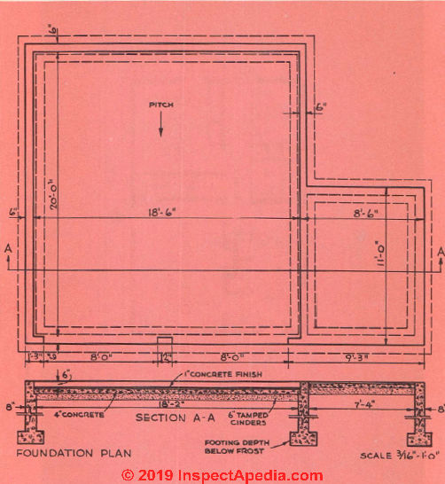
Foundation Plan of Garage and Breezeway
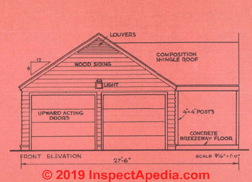
Above: Front Elevation of Garage and Breezeway
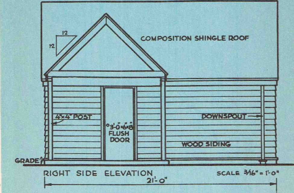
Above: Right Side Elevation
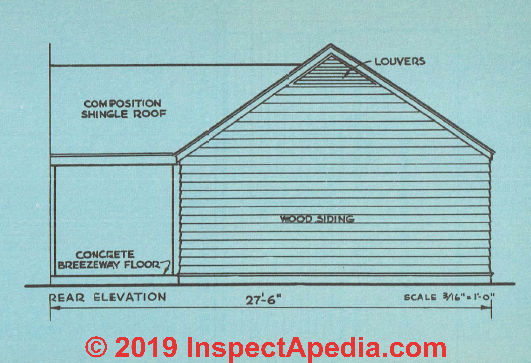
Above: Rear Elevation of Garage and Breezeway
Above: Left Side Elevation of Garage
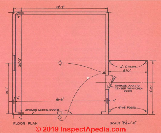
Above: Garage & Breezeway floor plan & electrical wiring plan. Scale 3/16" = 1 ft.
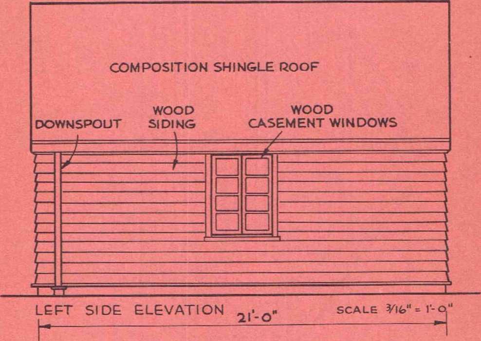
Above: Garage left side elevation. This is a 21' 0" deep garage. Scale 3/16" = 1 '
Above: Framing Plan of Garage. Below: framing plan of breezeway.
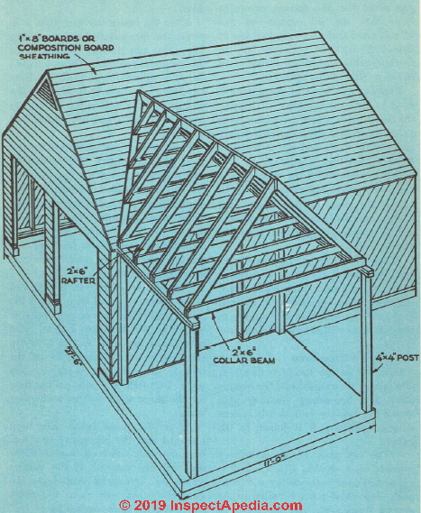
Framing the walls of the garage is done in the same manner as framing the house, with a few exceptions. One exception is that the corner braces are made of 2" x 4"s and set at the four corners. Another exception is that 2" x 8"s are used for the ceiling joists and roof rafters rather than 2" x 6"s, as was the case with the house. This is because the garage rafters have a longer unsupported run than the others.
When the garage framework has been completed, it should be covered with wood or composition-board sheathing. This procedure is covered in the following section and applies to the garage as well as to the main house.
Framing the Breezeway
Once the garage has been sheathed, you can go ahead and build the breezeway. The breezeway framing plan shows the manner in which it is constructed and how it is joined to the garage.
The top plate of the breezeway consists of a double 2" x 4" that is supported near each end by a 4" x 4" post. One set of posts is nailed to the garage framework and the other to the house frame. The ends of the posts that rest on the concrete slab should be coated with asphalt paint to prevent decay.
After the breeze way top plate is in place, you can install the three ceiling joists that run through the middle of the breezeway ceiling. Do not install the end ceiling joists until you have installed the rafters at both ends. The ceiling joists as well as the rafters are made of 2" x 6"s and are spaced 16" on center.
Three ceiling joists spiked to the top plate should provide the breezeway with sufficient strength so that the rafters can be installed without causing any damage. The end rafter next to the house on the rear side follows the same line as the house rafters but it does not extend up quite so far. The opposite rafter can be spiked into the house wall studding.
Put up a set of rafters at each end of the breezewav and then install the ridge pole. This, as you will note, is cut off so that it makes a clean joint with the garage roof. A 2" x 6" is run from this point down each side of the roof to join with the breezewav top plate. This will serve as a nailing base for the three small rafters and collar beams.
After the main house has been sheathed and the breezewav roof has been covered with roof boards, flashing will be required at the valleys where the breezewav roof joins the garage roof as well as at the point where it joins the house siding.
For the valleys, the flashing must extend from a point a little above the ridge pole down to the eaves of the garage roof. All flashing, both for the valleys and between the breezeway roof and the house siding, should extend 6" on each side. The flashing will eventually be covered by the roofing on the garage and breezeway or by the breeze-way roofing and the house siding.
Sheathing the Home
After the four walls have been framed, plumbed and braced, the next job is to apply the sheathing over the outer surface of the wall framework. Sheathing serves several purposes. It helps to brace the entire wall structure. It also has some value as insulation in addition to making the wall airtight. Wood sheathing will further serve as a nailing base for the wall siding. And last but not least, sheathing gives considerable hope to the amateur builder because it goes on fast and, when it is in place, the structure begins to look like a house and not just a miscellaneous collection of 2" x 4"’s.
Materials for Sheathing
There are several common materials that you can use for sheathing. One is regular sheathing boards, 1" x 6", 1" x 8", or 1" x 10". This is the same lumber as used for the forms for the concrete foundation. Another kind of wood sheathing is plywood, which comes in sheets 4' x 8'. Composition sheathing board, also called insulating sheathing, is another type. Each type of sheathing has certain advantages and disadvantages.
As far as cost goes, wood sheathing is the least expensive of the three, especially if the forms used for the concrete foundations are knocked down and the lumber is used for the sheathing; on the other hand, it requires a good deal more work to apply it to the wall, as each piece must be separately measured, sawed and nailed.
The other two materials are applied to the wall a section at a time and only a minimum of measuring and cutting is required. Insulating sheathing will provide more insulating value than the other two types, but it cannot be used as a nailing base for siding.
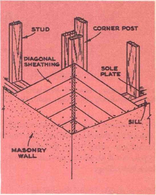
Fig. 16. Correct method of applying diagonal wall sheathing. Note that the sheathing runs right down over the edge of the sill. The sheathing should be nailed with two nails where it crosses framing members except for the comer post where three nails are used to help tie the comer post together.
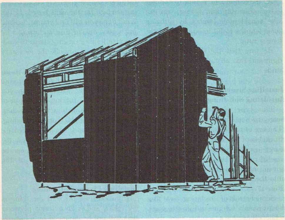
Fig. 17. Large sheets of structural fiber* board insulating sheathing make the job of sheathing the house a very simple matter for the owner-builder.
How to Apply Wood Sheathing
There are two ways in which wood sheathing can be applied to the framework. One method is to nail the boards on horizontally and the other is to have them run diagonally to the studding. There is no doubt that sheathing can be applied much faster if the horizontal method is used. But by nailing it on diagonally, you get the maximum stability and strength in your wall.
The sheathing boards should be nailed to the studding with two 8d nails. If you use the wider-size boards, such as 1" x 8" or 1" x 10", use three nails. Sheathing should be nailed at each point where it crosses studding. When sheathing is applied diagonally, it should run right down to the sill and should be nailed to the sill as well as the studding. This ties the sill and studding together. See Fig. 16.
At the cost of a little time to do some extra measuring and fitting, you can save considerable lumber by utilizing short lengths to fill in one some of the longer runs.
Be sure that the sheathing is laid tight and that all the joints come over studs.
Installing Structural Fiberboard Insulating Sheathing
This type of sheathing comes in many sizes and in different thicknesses. The size of nail used will depend on the thickness of the material; the manufacturer usually recommends the right size of nail. If this information is not given, select a nail that will penetrate into the studding for at least 1 1/4". See Fig. 17.
Some brands of insulating sheathing board have a tongue-and-groove edge, while others have a plain edge. Still others have a shiplap joint or a v-groove. These boards should never be butted close together because of the possibility of expansion and buckling. Leave a space of about 1/8" between boards.
Be sure that all joints come over studs. When you apply these boards it is important to center the ends accurately over studs and other frame members so that you leave enough nailing surface for the next board. If this is not done you will find yourself spending a good deal of time and using a lot of extra lumber tacking strips to studding in order to provide the necessary nailing surface.
If you use structural fiberboard insulating sheathing and you plan to use shingles for the exterior siding, you will need 1" x 2" furring strips applied over the sheathing to act as a nailing base for the shingles. Horizontal siding, on the other hand, can be applied directly over the sheathing without the need of any furring, because it can be nailed to the studs in back of the sheathing.
See details at FIBERBOARD SHEATHING
Installing Plywood Sheathing
Plywood used for wall sheathing is 5/16" thick [or nominal 1/2" thick CDX plywood that may be 15/32" thick on modern homes - Ed.] and is an exterior plywood that will not be damaged by moisture. It can serve as a base for shingles or horizontal siding. Special barbed nails
are used to apply shingles, wood or asbestos, to the plywood. Plywood is nailed, and often glued as well, to the studding. This combination of nails and glue will give you great structural strength. However, it takes time to achieve it.
Also see these article collections
EXTERIORS of BUILDINGS - home
PLYWOOD Roof, Wall, Floor Decks & Sheathing
WATER BARRIERS, EXTERIOR BUILDING - house wrap, building paper, moisture barriers, air barriers
Frame Openings For Doors And Windows
If vou went ahead and framed all the outside walls without leaving any openings for doors and windows, these should be made now. The elevation plans give the dimensions for these openings. These dimensions are for the particular stock window and door frames used in the plans.
If you use frames of somewhat different size, check with your local dealer and get the rough framing dimensions for those particular window and door frames. This is important, for the measurements of various frames will often differ.
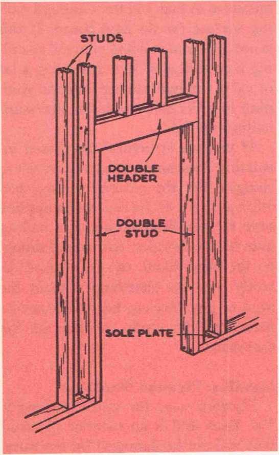
Fig. 18. Shows correct method of framing a door opening. The studs at the sides are double as well ag the header. The inside stud runs from the floor to the bottom of the header while the outside stud runs from the gole plate' up past the header. The header can be 2"x4" or 2"x6". These should be set on edge to provide maximum support and prevent the header from sagging.
You should not have much trouble making the openings. First of all, tack some temporary braces across the studding that is to be cut. This will hold it in place while you make the cuts and keep the ends of the studding from moving out of plumb before you have been able to complete the frame.
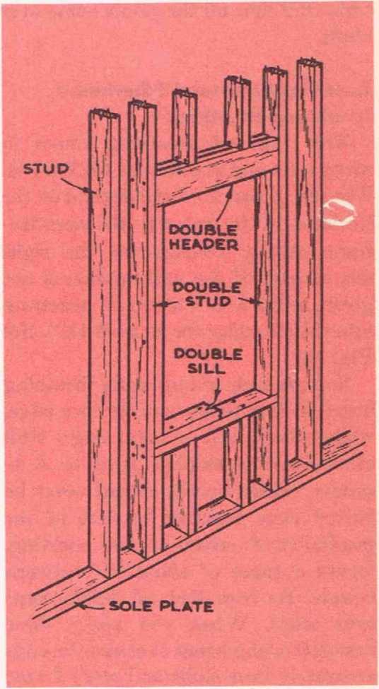
Fig. 19. Method used to frame opening for window. All framing is double. Note that the inside stud is cut out so that the double sill is supported at the ends. Short lengths of studg are placed under the sill to provide added support. The header is of 2"x4" or 2"x6" and this should be placed on edge and supported at the ends by the inside studg of the opening.
Note that the studding around all the openings is double. The 2" x 4"’s at top and bottom are set on edge to give maximum support to the opening. As the thickness of these two pieces of studding will not be quite sufficient to bring them out flush with the edges of the vertical studding, shim them out a little with strips of wood lath so that all surfaces, inside and out, are flush.
You can save a lot of time and trouble later on by making the openings for doors and windows as accurate as possible. If the rough opening is correct, you will have no trouble installing the frame later on. See Figs. 18 and 19.
Be sure that the rough frames for doors and windows are adequately nailed or else they will stick and the surrounding plaster will crack.
Also see our index to articles
at WINDOWS & DOORS, AGE, TYPES - home
Final Framing of Floor Openings
The first step is to cut off the ends of the joists that will form the tail beams. These cuts must be plumb, as a tight fit between the ends of the tail beams and the header joist will increase the strength of the opening. Now, cut a single header joist that will just fit between the two single trimmer joists. Nail a strip of 2" x 4" along one side of the header, allowing its edge to come flush with the bottom edge of the header. Use 20d nails for this job.
There are two methods of supporting the header between the trimmer joists. One method is to use metal joist-hangers. If a joist-hanger is used, the trimmers can be doubled before the header is installed. The other method of supporting the headers is to nail a ledger strip of 2" x 4" along the bottom edge of the trimmer joists and notch out the bottom edge of the headers so that they fit over it.
After the bottom edge of the tail beams has been notched and the ledger strip has been nailed to the bottom edge of the trimmer, the first header is put in place and nailed to the tail beams. Then the second header is installed and nailed to the first. The notches in the tail beams should be made with accuracy, as a good fit over the ledger strip is essential.
The header is nailed to the single trimmer by driving 20d nails through the trimmer into the header. Be sure not to double the trimmer at this time. The single header is nailed to the tail beams by driving nails in through the face of the header into the ends of the tail beams. When this has been done, the second part of the header is put into position, notched to fit over the ledger strip on the trimmers and then nailed to the first header and to the trimmer. After this, the second trimmers are installed and spiked to the first.
Scaffolding
From here on out there is going to be be given to adequate scaffolding. Good a good deal of work done beyond reach scaffolding is not only important to from the ground, so some thought must avoid injury, but you will be amazed at how much faster the work goes if you have a good solid base to work from.
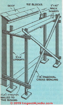
Fig. 20. Scaffolding of this type can be built on the job with the materials at hand.
Fig. 20 shows a type of scaffolding that is easily constructed from the materials you have on hand. Just like the forms used for concrete, the materials used for scaffolding can be used again on the house, so do as little cutting as possible. Scaffolding should be solid but should not be so heavy that it must be taken apart before it can be moved from one location to another. Fig. 21 shows another type of scaffold that is pvit up on a scaffold jack. You can build a jack yourself or buy one ready-made. Its great advantage is that the scaffolding can be moved from one location to another very quickly.
Do not neglect spending a little extra time rigging good scaffolding, because in the long run it will actually save you time.
A ladder is a very poor substitute for scaffolding. To be safe on a ladder you should have one hand free to hold on with. As most of the jobs in building a house require the use of two hands, working from a ladder is a definite hazard. Also, there is no place on a ladder to store either tools or materials, which means that you will forever be running up and down, wasting both time and energy.
[However two or more ladders combined with ladder jacks, a hinged brace that forms support for scaffold planks can provide inexpensive, quickly-erected scaffolding that is far easier to move than site-built wood scaffolding. - Ed. 2019]
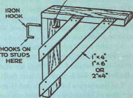
Fig. 21. A scaffold hook such as shown above makes it possible to erect scaffolding quickly on any side of the building. A hole must be cut through the sheathing to allow the hook to extend in back of the studding, thus it can get a tight hold.
Framing Ceilings: Ceiling Joists
The ceiling joists for the Basic House are 2" x 8"s. These will be sufficient here, even if you plan to finish off the attic at a later date.
For the most part, these joists are installed in the same manner as the joists used on the first floor. They will run between the top plates of the walls and of the main bearing-partition. They are spaced every 16" on center except around the openings for the stair well and the chimney, where they are doubled.
The two end ceiling-joists should be spaced 1 5/8" from the outer edge of the top plate of the walls. This is to allow room for the roof rafters, which should be set flush with the edge of the top plate. The joists are nailed to the top plate with two lOd nails on one side.
Later on, when the roof rafters are in place, the joists will be nailed to them and the rafters in turn nailed to the top plate. The joists meeting over the main bearing-partition can be fastened with five lOd nails. The upper corner of each joist-end resling on the top plates of the walls will have to be cut off so that it will be flush with the edge of the roof rafter, but this can be done after the rafters are in place.
As was the case with the first-floor joists, you will need bridging for the ceiling joists. Do not nail the lower ends of the bridging in place imtil the sub-floor has been nailed down.
Rather than take the time at this point to cover the joists with sub-flooring, it is best to move right on and get the roof framed so that it can be covered. There is a great advantage in
getting the house weathertight just as soon as possible—it will provide a safe as well as a dry place for storing various building materials, and this will save you time by allowing you to order enough materials for several different jobs.
It is a good idea, however, to bring up the lumber for the sub-floor and lay some of it across the joists so that you will have a surface to walk on and work from. Also, after the roof has been finished, hauling up all this lumber is going to be rather difficult, so it is best to get it up now.
Roof Framing
Fig. 22 shows a master rafter that gives you the exact length that the rafter must be and also the angles for the two cuts. You will need 61 rafters and they should be 2" x 6" stock. Be sure that you cut each rafter accurately. The first job is to install the four end rafters. These should come flush with the outer edge of the top plate.
Use braces to hold each rafter in position. The heel cut of the rafter must sit for its entire surface on the top plate. As soon as you have one rafter up, put up the other one to complete a pair. You will notice that there is a slight gap between the tops of the rafters. This is for the ridge board. You can make a ridge board out of several pieces of 1" x 6".
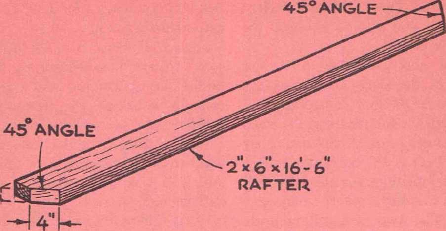
Fig. 22. Dimension, plumb and heel cul All rafters should be cut to this exact size for the roof rafter of the basic house, to insure a perfect fit.
They will have to be spliced together and the splices must come between rafters. Rafters are spaced 16" on center. As soon as the two pairs of end rafters are in place, go ahead and install the intermediate rafters.
Put them up in pairs. Nail the first rafter to the ridge board with two 16d nails driven in through the ridge board into the face of the rafter. Nail the end of the rafter to the ceiling joists with five lOd nails. Secure the rafter to the top plate with two lOd nails toe-nailed in. The second rafter in the pair is nailed through its top with one 10d nail to the ridge board and then another 10d nail is toe-nailed in. See Fig. 23.
Tack temporary braces across the rafters to hold them in place until the roofing has been applied. If a rafter has a slight crown, the crown should face up.
To tie the rafters together and to provide a ceiling for the attic space, collar beams are installed. The bottom of these should be spaced 7' 2/4" from the top of the ceiling joists and spiked right to the sides of the rafters. Cut off their upper comers flush with the rafter. 1" x 6"s are used for the collar beams.
The next step is to frame the gable ends. This studding should be spaced 16" on center and should come directly over the studding below. All studs should be notched as shown in Fig. 24, so that they will fit up alongside the rafters. Two 10d nails are used to nail the studs to the rafters.
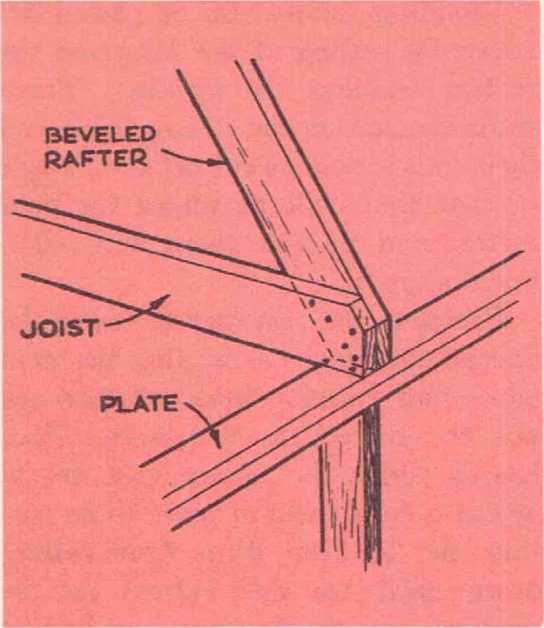
Fig. 23. Detail showing joint between rafter, ceiling joist and top plate. Joist and rafter are nailed together and toe-nailed to the plate with two nails driven in through the rafter and two through the joist.
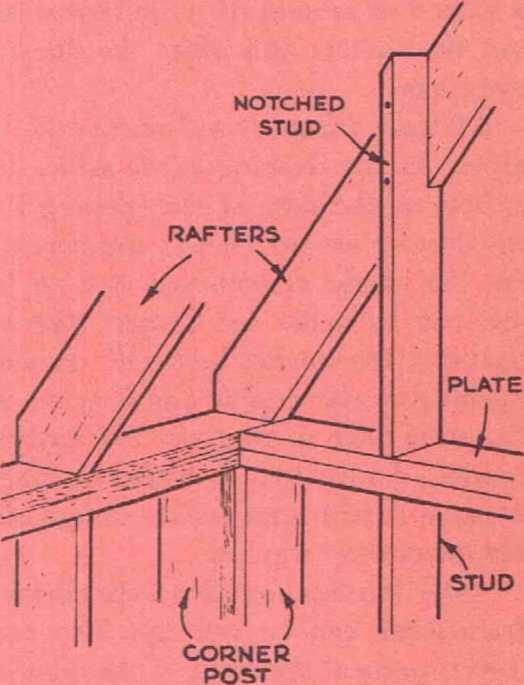
Fig. 24. Studding at the gable ends must be notched out at the top so that it will fit around the roof rafters. The bottom of the notch is cut to the same angle as the roof pitch. After the stud is in place, its top can he cut off flush with the top of the rafter.
a standard stock-size louver. If you wish to install windows instead of louvers at the gable ends, the frames for them should be doubled.
The studs are nailed to the top plate with two 8d nails on each wide side. You will need an opening for a louver at each gable end. This should be framed to take
See details at ROOF FRAMING TIES & BEAMS
Frame Dormer Windows
You do not have to spend time money at this point to complete the dormer windows in the attic, but if you plan to put them in later on, you will be wise to make the necessary frames in the roof at this time. If you do this, you will not find it very difficult to put the windows in whenever you choose, and it will not be necessary to have an opening in the roof for a period of several days while you cut out the rafters and make the dormer openings.
All three dormers are framed exactly alike. As the framing plans show, the rafters on the sides of the opening for the dormer are doubled to compensate for the inside rafters that had to be cut out to make the proper size of opening. The top header for the dormer opening is also double and it is set at the same pitch as the roof. The bottom header, double too, is placed upright because it will serve as the rough sill for the dormer window.
After this has been done, the dormer framework can be put up. The two corner posts at the front of the dormer are doubled and are nailed into the double rafters framing the dormer opening. Additional studding is spaced 16" on center and is also nailed to the tops of the roof rafters.
Studding should also be placed between the ceiling of the attic and the rafters framing the opening. These studs can rest on the ceiling joists and their ends should be cut off at an angle so that they will fit under the roof rafters and provide them with additional support.
Probably the best way to frame the dormer opening is to complete the main house-roof framing first and then cut out the rafters as necessary. Tack boards across the rafters that are to be cut to hold them in place while cutting and to keep them from falling down until the side rafters can be doubled and the headers installed at both top and bottom.
When this has been done, a rafter can be put back into the center of the opening and spiked to the top and bottom headers. When the time comes to install the dormer, the only additional framing work to do will be the removing of that one temporary rafter.
Roof Boards / Roof Sheathing
In all cold climates and wherever asbestos or composition shingles are to be used, the roof should be completely sheathed with roof boards.
These can be either shiplap or matched tongue-and-groove. The joints between the boards should be staggered so that no more than two of them fall on the same rafter. The board should be nailed with two 8d nails to each rafter. A good tight deck-roof of this type will do much toward keeping the house warm, so be sure that the boards are tightly laid together.
The chimney should be built before the roof boards and roofing material are put on. The chimney can be installed after the roof boards are in place, but it is obviously easier to do it before.
You should have no difficulty getting the roof boards in place quickly. To save time, do not bother to trim the ends of the boards one at a time. Let them hang over a little and, when the roof has been covered, just trim them off with a saw.
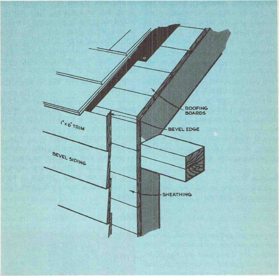
Fig. 25. Detail of cornice trim construction. It is worth the added effort to back prime the cornice material before it is installed.
Lay the roof boards horizontal and level from the eaves up. As you move up the roof, you can nail temporary walking strips to them so that you can get about more easily and safely.
In warm, moist climates where wood shingles are used, it is customary to place the roofing boards with a space between them equal to the length of the shingle that is laid to the weather. The reason for this practice is that in these climates the shingles may rot if they are fastened to a tightly sheathed roof. The space between the roof boards will provide enough ventilation to prevent decay. This type of roof is called a slat roof.
Roof boards should be laid from the eaves up. You will have to trim off the little corner of the ceiling joist so that it is flush with the edge of the rafter. You can use a saw for this purpose, but a hatchet is much quicker.
Before the roofing material can be applied, the cornice trim should be installed, the gutters hung and the chimney built. However, if the roof is covered with sheathing and it is laid tightly, it will offer a great deal of protection against the weather.
Cornice Trim
1" x 6" stock is suitable for the cornice trim. Because of the simplicity of the roof frame, only one strip of wood will be required. This will be nailed along the front edge of the roof rafters where they join the ceiling joists and top plate. The cornice trim at the eaves should make a tight butt joint with the roof sheathing. The same method of application can be used as at the gable ends of the house. See Fig. 25.
All cornice trim should be back painted before it goes into place, and it is wise to use a wood that has a high resistance to decay, such as cypress, which is highly resistant.
After the cornice is in place, it should be painted, and this must be done before the gutters are in place because once they are hung, getting in back of them with a brush will prove to be difficult.
Gutter Installation
You can use gutters of wood, galvanized iron, copper or aluminum. Wood gutters are serviceable but should be kept well painted on the outside, and the inside should be coated with roofing compound or metal to prevent decay.
Galvanized iron gutters will give many years of good sendee if they are kept painted—inside and out. Copper gutters will last indefinitely, but they tend to cause stains on white siding unless they are coated with paint or varnish, neither of which will stick to the copper unless it has had time to weather. Aluminum is weather resistant and will not cause stains. But if aluminum
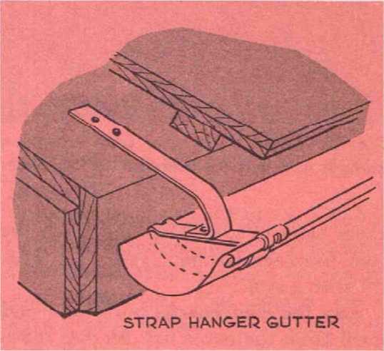
Fig. 26. Gutter hangers should be installed before the roofing is applied and should be nailed to roof sheathing.
gutters are used and the flashing is copper, the two metals should not come into contact with one another; insulate them with roofing compound, or they will set up a corrosive action. Properly hung gutters should slope about Vie" per foot towards their outlet. The outside edge of the gutter should be below the pitch of the roof. Be sure that enough hangers are used and that they are securely fastened to the roof. See Fig. 26.
See our complete article series
at GUTTERS & DOWNSPOUTS - home
Roof Covering Materials
As far as cost is concerned, the least expensive roofing you can use is roll roofing. This is a heavy felt-and-as-phalt material that comes in rolls 36" wide. Each roll will cover about 100 square feet. While roll roofing offers good protection against the weather, it is seldom used on homes because it presents a rather drab and uninteresting appearance.
How to Install Asphalt Shingles
A more popular type of covering is asphalt shingles. These come as individual shingles or in strips of from two to four shingles each. They give protection and many years of service and come in many designs and colors. Fig. 27 shows several types of asphalt shingle. Consult the manufacturer’s directions as to the size and number of nails required for each strip of shingles.
The first step in applying this type of roofing is to cover the roof with roofing felt. This should be applied in horizontal strips from the eaves to the ridge board. Each strip should overlap the strip below it about 6" and the topmost strip should also go over the ridge board. Roofing felt needs to be nailed only in a few places to hold it down. Before these strips go down, check over the wood sheathing to be sure that there are no nail heads sticking up, as these may easily puncture the material and cause the roof to leak.
Now tack a course of wood shingles along the eaves. These should extend beyond the eaves and the gable ends of the roof from Vi" to Their purpose is to provide a firm base for the first course of asphalt shingles. The first strip of felt goes over these shingles.
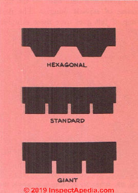
Fig. 27. Asphalt Shingles.
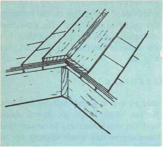
Fig. 28. If you prefer, the ridge of the roof can be covered with a wood ridge-cap. For this purpose, l"x6" stock is suitable. The underside of the cap should be painted before it is nailed in place.
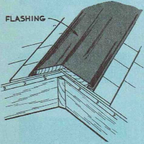
Fig. 29. After the roofing is in place, the seam at the ridge can be covered with stock metal ridge-flashing.
Now apply the first course of asphalt shingles. Apply successive courses from the eaves upward. Lay the shingles tightly and stagger the joints from course to course. You don’t have to worry about how much of the shingle . hould be exposed because this is clfc \rly indicated on each one.
A common practice in applying felt and shingles is to put down a section or two of felt and then the shingles before moving on to the next section of felt.
It is not advisable to work with asphalt shingles in very hot weather because they become rather soft and can be damaged by being walked on. Bring up enough bundles of shingles to do the job before you start work so that you will not have to be walking back and forth over the completed portion of the roof with various materials.
The ridge of the roof can be capped with shingles, a strip of roll roofing, or wood or metal ridge caps. See Figs. 28 and 29.
How to Install Wood Shingles
Wood shingles are considerably more expensive than asphalt shingles, especially if edge-grain, all-heartwood shingles are used. Flat-grain shingles are less expensive but they have more tendency to curl and split and do not have as good weathering characteristics as the others. Unless you can afford the best quality of shingles, you will do better to roof with asphalt shingles rather than wasting time and money on gles that sooner or later will have to be replaced.
Wood shingles come in lengths of It)", 18" and 24". The amount of exposure (the length laid to the weather) will depend on the length of the shingle: 16" shingles can be given 5" of weather exposure; 18" shingles, oV2"; and 24" shingles, 7Shingles come in random widths. If the shingles are laid over a tight deck-roof, the roof should first he covered with a rosin-treated paper. If a slat roof has been built, the paper is not necessary.
Shingles are often stained with a preservative that not only helps them resist decay but gives them a touch of color. The best time to stain the shingles is before they go on the roof. Have a large container of the stain on hand and dip each shingle to within about 3" of the covered end. Now stand the shingle in a wood trough until the stain is dry. Shingles can be stained after thev are in place but in that case only a small portion of the shingle can be coated. Do not paint wood shingles on a roof. The paint may seal moisture inside the shingles and cause them to decay.
The first course of shingles, at the eaves, should be double. The joints between shingles in each course must be staggered so that each joint is covered by at least l!4" of the width of the shingle above. Dry shingles should be spaced %" apart. If the shingles are wret or green, this distance can be reduced to Vs". If the shingles are butted tight against one another, there may be buckling when the shingles become wet and swell. Nails used for shingles
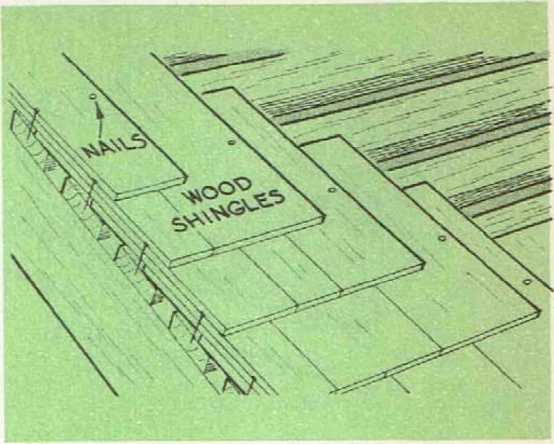
Fig. 30. Detail showing the proper nailing for wood roof shingles.
should be rust-resistant. The nails should not be placed more than 3/4" from the edges of the shingles and about 2" above the butt line of the course of shingles above. See Fig. 30.
This will allow all nails to be covered by the next course. For 16" and 18" shingles, use 3d nails, for 24" use 4d nails. You will need two nails for each shingle.
Do not try to use the wide shingles as they are easily split by the nails. It is better to split them in half before they are used. The best tool to use for working with wood shingles is a carpenter’s hatchet. This allows you to split the shingles and nail them without having to use two different tools.
The ridge can be capped either with wood or metal. If you use wood, 1" x 6" stock is perfectly suitable.
Use a line running parallel with the eaves of the roof or tack down a strip of wood so that you will be sure to get each course of shingles on evenly.
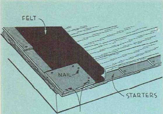
Fig. 31. How the first course of asbestos roof shingles should be applied.
Asbestos Cement Shingles
Asbestos shingles, made of Portland cement and asbestos fibers, are an excellent roofing material. They are highly resistant to fire and will not rot or decay. If properly installed they should last the lifetime of the house. They come in several colors and it is perfectly practical to paint them. Ordinary oil paints can be used, but special paints designed for this purpose are more satisfactory.
Asbestos shingles are very brittle, so you must be careful when handling and working with them not to crack or damage them. You have to be especially careful when nailing, because, if you should strike the shingle with your hammer, you may easily crack and ruin it.
Once the shingles are in place, do not walk over them. This will mean that you are going to need some sort of roof scaffolding for the job. This can be easily built by nailing two strips of wood to the end of a ladder and using them to hook the ladder over the ridge.
Asbestos shingles should be installed over a solid deck-roof. Be sure that all roof boards are secure, that they fit close together, and that they are perfectly dry before you start applying the shingles.
Once you are satisfied with the condition of the roof, cover it with 15-pound asphalt roofing-felt. All the seams between the strips of felt should be lapped at least 4". After all this has been done, nail a 1/4" by 1 1/2" strip of wood along the edge. Before you tack this strip of wood in place, roll back the edges of the roofing felt along the eaves; the first row of shingles is going to be double and this felt should be placed between the two layers. The strip of wood should be flush with the eaves of the roof.
The first row of shingles put down is of special starter-course shingles. This first course should extend about 1" beyond the eaves to form a drip edge. After this first layer of the first course is in place, roll the roofing felt down over it and apply the second layer. See Fig. 31.
The shingles are nailed with 1/4" galvanized nails driven through the holes provided for them in the shingles.
The amount of weather exposure will depend on the length of the shingle. This information can be obtained bv reading the manufacturer’s specification sheet.
Asbestos shingles can be cut by scoring them with a sharp instrument and then breaking along this line, or they can be cut with an asbestos-cement cutting machine, which you may be able to rent or borrow from your local dealer.
At the time that the roofing material is put on, the base flashing and cricket for the chimney should be in-stalled. See Figs. 12, 13, 14 and 15 in Chapter 9.
Watch out: sawing or breaking asbestos cement roof or siding shingles produced asbestos dust that was not widely understood as a health hazard in the 1950s. Current fiber cement roof shingles and fiber cement siding do not contain asbestos but silica dust hazards remain. Take appropriate measures for dust control and to avoid breathing the dust; wear appropriate clothing and respirator. - Ed.
Also see ROOFING INSPECTION & REPAIR - home
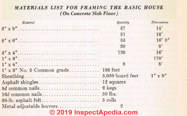
Materials List For Framing The Basic House
...
Continue reading at CHIMNEY & FIREPLACE CONSTRUCTION - next chapter in this book, or go to book contents at BUILD YOUR DREAM HOME, or select a topic from the closely-related articles below, or see the complete ARTICLE INDEX.
Or see these
Recommended Articles
- BATTER BOARDS LAYOUT METHOD
- BUILD YOUR DREAM HOME
- FIBERBOARD SHEATHING
- FRAMING DAMAGE, INSPECTION, REPAIR - home
- GLOSSARY of BUILDING TERMS
- GUTTERS & DOWNSPOUTS
- PLYWOOD Roof, Wall, Floor Decks & Sheathing
- ROOF FRAMING TIES & BEAMS
- SHEATHING, EXTERIOR PRODUCT INDEX
- TRUSSES, FLOOR & ROOF
Suggested citation for this web page
FRAMING THE HOUSE at InspectApedia.com - online encyclopedia of building & environmental inspection, testing, diagnosis, repair, & problem prevention advice.
Or see this
INDEX to RELATED ARTICLES: ARTICLE INDEX to BUILDING ARCHITECTURE
Or use the SEARCH BOX found below to Ask a Question or Search InspectApedia
Or see
INDEX to RELATED ARTICLES: ARTICLE INDEX to BUILDING DAMAGE, DISASTER, REPAIRS
Or use the SEARCH BOX found below to Ask a Question or Search InspectApedia
Ask a Question or Search InspectApedia
Share this article:Questions & answers or comments about how to identify the architectural style of buildings and building components
Try the search box just below, or if you prefer, post a question or comment in the Comments box below and we will respond promptly.
Search the InspectApedia website
Note: appearance of your Comment below may be delayed: if your comment contains an image, photograph, web link, or text that looks to the software as if it might be a web link, your posting will appear after it has been approved by a moderator. Apologies for the delay.
Only one image can be added per comment but you can post as many comments, and therefore images, as you like.
You will not receive a notification when a response to your question has been posted.
Please bookmark this page to make it easy for you to check back for our response.
IF above you see "Comment Form is loading comments..." then COMMENT BOX - countable.ca / bawkbox.com IS NOT WORKING.
In any case you are welcome to send an email directly to us at InspectApedia.com at editor@inspectApedia.com
We'll reply to you directly. Please help us help you by noting, in your email, the URL of the InspectApedia page where you wanted to comment.
Citations & References
In addition to any citations in the article above, a full list is available on request.
- In addition to citations & references found in this article, see the research citations given at the end of the related articles found at our suggested
CONTINUE READING or RECOMMENDED ARTICLES.
- Carson, Dunlop & Associates Ltd., 120 Carlton Street Suite 407, Toronto ON M5A 4K2. Tel: (416) 964-9415 1-800-268-7070 Email: info@carsondunlop.com. Alan Carson is a past president of ASHI, the American Society of Home Inspectors.
Thanks to Alan Carson and Bob Dunlop, for permission for InspectAPedia to use text excerpts from The HOME REFERENCE BOOK - the Encyclopedia of Homes and to use illustrations from The ILLUSTRATED HOME .
Carson Dunlop Associates provides extensive home inspection education and report writing material. In gratitude we provide links to tsome Carson Dunlop Associates products and services.
 |
HOME | ABOUT | ASK a QUESTION | CONTACT | CONTENT USE POLICY | DESCRIPTION | POLICIES | PRIVACY | |
| © 2026 - 1985 Publisher InspectApedia.com - Daniel Friedman | |||||||||