
InspectAPedia® FREE Encyclopedia of Building & Environmental Construction, Diagnosis, Maintenance & Repair |
Question? Just ask us! InspectAPedia
|
 Electrical Branch Circuit & Service Entry Wire Sizes & Ampacity Tables
Wire Size Tables for Normal & Long Electrical Wire Runs

- POST a QUESTION or COMMENT about electrical wire sizes, diameters, and ampacity ratings
Electrical wire sizes & gauges:
These Tables of Electrical Service Entry Cable Sizes, Electrical Circuit Wire Diameters, Circuit Ampacity, Allowable Voltage Drop, & Wire Size Increase based on Run Length assist in determining the electrical service size or other required electrical wire sizes at buildings.
We include tables of aluminum or copper wire sizes for long runs of service entry cables.
This article series gives photos and tables of electrical service entry cable sizes, electrical branch circuit wire sizes, bell wire, telephone wire, thermostat wire, and ampacity or fuse/circuit breaker ratings.
InspectAPedia tolerates no conflicts of interest. We have no relationship with advertisers, products, or services discussed at this website.
Service Entry & Electrical Cable or Wire Sizes vs Amps vs Run Length
 Here we discuss and present a table of electrical wire sizes, ampacity, and fuse or circuit breaker sizes for common residential electrical wiring circuits.
What is the diameter of service entry electrical cabling? What are the common diameters of household copper or aluminum electrical wiring?
What is the diameter of thermostat wire, telephone wire, bell wire?
How to determine the size, capacity, or ampacity of electrical service at a building. Illustration of common electrical wire sizes for both service entry cables and in-building electrical circuits: wire size versus circuit ampacity and fusing requirement.
[Click to enlarge any image]
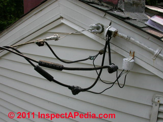
"How do I determine the service amperage?" Start by taking a look at the service entry cables outside and at their entry into the electrical panel.
A quick look can tell us if the property is served by 240V or only a 120V service, even before measuring the gauge or wire thicknesses that we discuss below.
In the photo above we see a three wire mast-head: 3 wires means that there are two 120V lines + a power company neutral. Two 120V lines usually give us a 240V service. But we did not like the position of that weather-head, and we considered that water may be entering the SEC.
This article series explains how to estimate the electrical service size (or "electrical power" or "service amps") at a building by visual examination of the service entry cables, electric meter and meter base, electrical service panel, main switch, and other details.
Tables of Wire Sizes vs. Circuit Amps vs. Wire Run Length
- INTRODUCTION to WIRE SIZES - size matters
- WIRE SIZE TABLE - Electrical Wire Sizes and Amps or Fuse Ratings - Residential - Bell wire up to 400 Amp 240V Circuits
- WIRE SIZE INCREASE for LONGER RUNS - 120V - 15A - 50A Branch Circuit Wire Size vs Run Length: 120V Circuits
- WIRE SIZE INCREASE for LONGER RUNS - 240V - 15A - 50A Branch Circuit Wire Size vs Run Length: 240V Circuits
- MAXIMUM WIRE RUN LENGTH for each WIRE SIZE - how long can the wire be without overheating?
- WIRE SIZE INCREASE using VOLTAGE DROP CALCULATORS - what to do if your wire size & length aren't in the table
- VOLTAGE DROP INDEX - allowable voltage drop in circuits
The tables above are for electrical circuits up to 50 Amps.
For larger wire sizes (higher Amps) (above 50A)
see SE CABLE & WIRE SIZES FOR LONG RUNS
Introduction to Choosing Electrical Wire Size
 The amperage that can be supported by any electrical wire is a function of its materials
and diameter and the run length.
The amperage that can be supported by any electrical wire is a function of its materials
and diameter and the run length.
Often the actual cable type and size is printed right on the cable insulation. Otherwise some rough measurements of cable
diameter are in order.
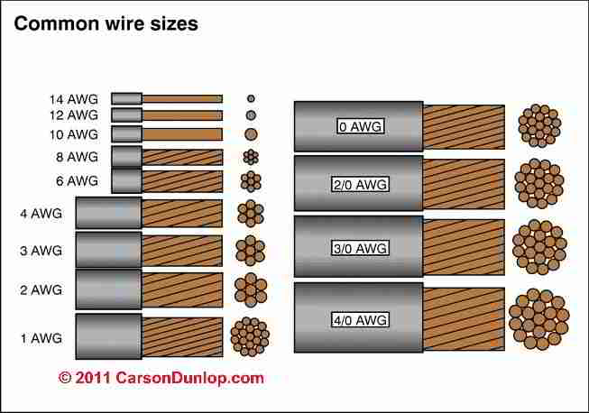
Carson Dunlop Associates' sketch shows common electrical wire sizes for both service entry conductors and in-building branch circuit wiring.
[Click to enlarge any image]
We use to use a plastic vernier caliper or other non metallic instrument to measure external (insulated) width of the whole cable as a reasonable guess at wire ampacity. Some inspection tool companies sell, and others give-away a plastic "wire gauge" with notches labeled to tell electrical inspectors the cable size for aluminum and copper SECs. Or you can make your own.
For a simplified table matching service entry cable size to ampacity
see SERVICE ENTRY WIRING & AMPACITY - a separate article.
Branch circuit electrical wire sizes such as the #14 copper electrical wire shown just below are included in the tables on this page where we give wire sizes for circuits from 15A to 50A.
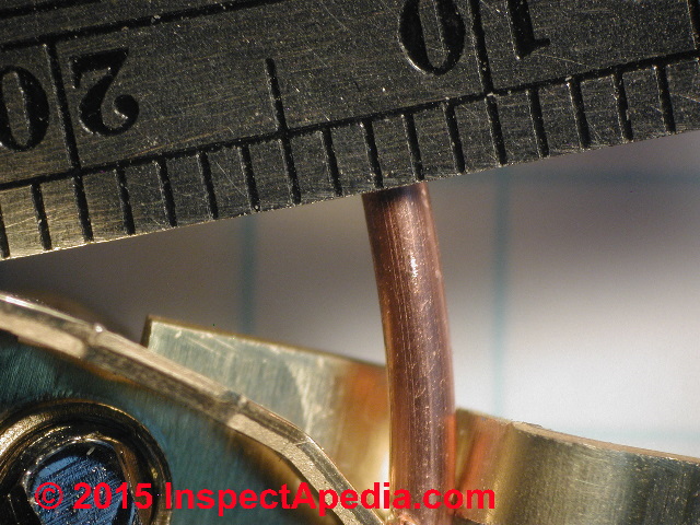
Above is a close-up photo of a #14 copper wire against a millimeter scale. The divisions on the scale of my metal ruler each represent 1 mm. You'll see that this wire looks as if it's about 1.5 mm in diameter. [Thanks to reader Max for careful reading 2018/06/14]
The actual wire diameter of #14 copper wire can vary among manufacturers and wire types.
The wire size table below gives the typical diameter of #14 copper wire as 0.073- .064 / 1.84-1.63 inches / mm. [Thanks to Anonymous for careful editing]
The tables and notes below expand and provide detail about the ampacity and temperature ratings of various wire sizes and gives a brief history of U.S. NEC wire sizing table changes. For copper wiring the following wire sizes and ampacity ratings or fuse/circuit breaker sizes are common on 120V residential electrical circuits.
Table of Common Electrical Wire Sizes and Amps or Fuse Ratings - ResidentialElectrical Wire Sizes vs Ampacities for 1-3 Current-Carrying Conductors in Cable, Earth, or RacewayCircuits used in 120/240-volt systems of total capacity between 100 and 400 amperes |
||||
| Electrical Conductor Wire Size or Gauge - AWG or kcmil | AMPACITY Rating COPPER Wire Conductors Recommend Max Fuse Rating |
AMPACITY Rating ALUMINUM Wire Conductors Recommend Max Fuse Rating |
Electrical Wire Overall Diameter (approximate) inches / mm |
Comments |
| "Bell wire" | / 0.5mm | Typical solid conductor telephone or bell wire size, thermostat wire, or 12-24V wire for controls | ||
| 20 | 0.036 / 0.91 | Also used for thermostat wiring [1] | ||
| 18 | 0.046-0.040 / 1.16-1.02 | Usually used for thermostat and HVAC control wiring | ||
| 16 | 0.058-0.051 / 1.46-1.29 | OK for thermostat and HVAC control wiring | ||
14 |
0.073- .064 / 1.84-1.63 | Smallest size normally used for household 120V wiring (copper 15A) | ||
12 |
20 / 20 / 25 15A in common house wiring applications |
0.092-0.081 / 2.32-2.05 | Smallest size normally used for household 120V wiring (aluminum 15A) | |
10 |
.116-.102 / 2.93-2.59 | |||
8 |
.146-.128 / 3.7-3.26 | |||
6 |
.184-.162 / 4.66-4.11 | |||
4 |
.232 / 5.88 | |||
2 |
.292 / 7.42 | Smallest copper size for a 100A panel | ||
1 |
.332 / 9.43 | Smallest aluminum size for a 100A panel | ||
| 1/0 or 0 | .373 / 9.46 | |||
2/0 or 00 |
115 / 135 / 150[5] |
.419 / 10.6 | ||
3/0 or 000 |
.471-.470 / 12.0-11.9 | |||
| 4/0 or 0000 | .528 / 13.4 | About the largest wire size likely to be found at residential electrical SECs | ||
Notes to the Table Above
1. See Article 100 (maximum amperage a conductor can carry under conditions of use without exceeding its temperature rating) and Article 310 of the U.S. National Electrical Code (NEC). The U.S. NEC can be purchased from electrical suppliers and online from nfpa.org.
Since some readers request historical data on electrical code provisions, we note that the data in this article has been excerpted / adapted from the U.S. National Electrical Code. The locations of wiring size vs ampacity ratings changed in the 2011 NEC and again in the 2014 NEC.
Prior to the 2011 NEC wire size vs ampacity table data was provided in NEC Table 310.16. Many sources continue to quote this table.
Beginning in 2011, the pertinent wire sizing tables were found in NEC Table 310.15(B)(2)(a) (Ambient Temperature of 30°C) and NEC Table 310.15(B)(2)(b) (Ambient Temperature of 40°C). Ampacities of not more than three current-carrying conductors in raceway, cable, or earth, were typically based on an ambient temperature of 86°F / 30°C.
This excerpt from the 2014 NEC explains:
310.15(B)(7) For one-family dwellings and the individual dwelling units of two-family and multifamily dwellings, service and feeder conductors supplied by a single-phase, 120/240-volt system shall be permitted be sized in accordance with 310.15(B)(7)(a) through (d).
(a) For a service rated 100 through 400 amperes, the service conductors supplying the entire load associated with a one-family dwelling or the service conductors supplying the entire load associated with an individual dwelling unit in a two-family or multifamily dwelling shall be permitted to have an ampacity not less than 83% of the service rating.
(b) For a feeder rated 100 through 400 amperes, the feeder conductors supplying the entire load associated with a one-family dwelling or the feeder conductors supplying the entire load associated with an individual dwelling unit in a two-family or multifamily dwelling shall be permitted to have an ampacity not less than 83% of the feeder rating.
(c) In no case shall a feeder for an individual dwelling unit be required to have an ampacity greater than that of its 310.15(B)(7)(a) or (b) conductors.
(d) Grounded conductors shall be permitted to be sized smaller than the ungrounded conductors provided the requirements of 220.61 and 230.42 for service conductors or the requirements of 215.2 and 220.61 for feeder conductors are met.
Informational Note No. 1: It is possible that the conductor ampacity will require other correction or adjustment factors applicable to the conductor installation.
Informational Note No. 2: See example in Annex D.
2. Assuming the electrical current in these wires is AC or DC at 60Hz or less.
3. The U.S. National Electrical Code NEC 240-3 requires that the electrical branch circuit, feeder wire, and electrical service conductors shall be protected against overcurrent in accordance with their ampacity ratings as specified in NEC Table 310-16.
4. Additional NEC rules that pertain are in NEC Sections 210-20 (a), 215-3, and 384-16(d). Also NEC Section 240-6(a) gives a list of standard wire sizes and overcurrent protection (fuse or circuit breaker) required.
5. For dwelling units, conductors, as listed below, shall be permitted as 120/240 volt, 3 wire, single phase service-entrance conductors, service lateral conductors and feeder conductors that serve as the main power feeder to a dwelling unit and are installed in raceway or cable with or without an equipment grounding conductor.
For application of this section, the main power feeder shall be the feeder(s) between the main disconnect and the lighting and appliance branch-circuit panel board(s) and the feeder conductors to a dwelling unit shall not be required to be larger than their service entrance conductors. The grounded conductor shall be permitted to be smaller than the ungrounded conductors provided the requirements of Sections 215.2, 220.22 and 230.42 are met.
6. For information about copper clad aluminum wiring
see COPPER-CLAD ALUMINUM WIRE
Branch Circuit Wire Size vs Run Length: 120V Circuits, <=5% Voltage Drop
120V Branch Circuit Wire Sizes Needed for Longer Run Lengths |
||||||
Maximum Run Length in Ft. vs AWG Wire Size, 120 VAC* Single Phase @ <= 5% Voltage Drop |
||||||
| Wire Material | AMPS** | 120VAC Circuit Wire Size AWG |
||||
| 25 ft. | 50 ft. | 100 ft. | 150 ft. | 200 ft. | ||
| Copper | 15A1 | #14 | #12 | #10 | #8 | #6 |
| Copper | 20A | #12 | #12 | #8 | #6 | #4 |
| Aluminum 2 | 20A | #8 | #8 | #8 | #6 | #6 |
| Copper | 30A | #10 | #10 | #6 | #4 | #4 |
| Aluminum 2 | 30A | #8 | #8 | #6 | #4 | #4 |
| Copper | 40A | #8 | #8 | #8 | #6 | #4 |
| Aluminum | 40A | #8 | #8 | #6 | #4 | #3 |
| Copper | 50A | #8 | #8 | #6 | #4 | #4 |
| Aluminum | 50A | #6 | #6 | #4 | #3 | #2 |
Notes to the table above
- Branch circuit wire sizes for long runs: The long-run wire sizes given in the table above are for typical residential branch circuits up to 50A.
- Service entry cable wire sizes for long runs: Detailed tables of copper or aluminum Service Entry Wire SEC cable sizes for long runs at higher ampacities entering the building's main electrical panel, and where we give sizes for both single phase and three phase power are at
SE CABLE & WIRE SIZES FOR LONG RUNS - separate page - Sources include Cerrowire, "240 Volt, Conductor Size (AWG or kcmil)
Single Phase, Max 3% Voltage Drop" retrieved 2021/12/03 original source: Cerrowire, https://www.cerrowire.com/products/resources/tables-calculators/voltage-drop-tables/
Notes included by Cerrowire:
*The tables assume steel conduit, a power factor of 0.9, an ambient temperature of 86°F, and no more than 3 current-carrying conductors. We have taken reasonable care to establish the accuracy of these values; however, this tool is intended only as a guide, consult a professional engineer to determine suitability for your application.
**Based on 60°C per NEC 110.14(c)(1)(a).
***Based on 75°C per NEC 110.14(c)(1)(b). - VOLTAGE DROP TABLE, [PDF], retrieved 2017/09/26, Cerrowire LLC, 1099 Thompson Road SE, Hartselle AL 35640, USA, Tel: 256-773-2522, original source: http://www.cerrowire.com/files/file/voltagedrop.pdf
300 ft and 400 ft cable length data: Cable size recommended based on voltage drop calculations. Calculated by Online voltage drop calculator: 2019/07/23, Southwire, Tel: 1-800-444-1700 Website: www.southwire.com Email: CableTechSupport@southwire.com Web page: https://www.southwire.com/calculator-vdrop
- Watch out: the engineering work and derivation of the table above is derived from the sources listed below including manufacturer's tables and online voltage drop calculators but may not be correct for your specific installation. Check with your engineer or electrician.
- These circuits are 120VAC (single phase) single conductor. Three phase power typically reduces the wire size to the next smaller.
- Watch out: These aluminum solid conductor wires should NOT be used in new residential branch circuit wiring such as for lighting or electrical receptacles but may be found in older homes built in the 1970s.
However multi-strand aluminum wiring is used in special or single purpose circuits in new work such as for high-amperage devices like an air conditioner compressor. Proper wiring and connection details are required for such circuits to perform reliably and safely.
See ALUMINUM WIRING HAZARDS & REPAIRS - home - Unlike the service entry cables, branch circuits may permit up to a 5% voltage drop but
Watch out: a limit of 3% voltage drop is the most-common recommended limitation on wire size vs run length for residential properties - Cable size recommended based on voltage drop calculations. Calculated by Online voltage drop calculator: 2019/07/23, Southwire, Tel: 1-800-444-1700 Website: www.southwire.com Email: CableTechSupport@southwire.com Web page: https://www.southwire.com/calculator-vdrop
- Watch out: these are example wire or cable sizes vs. run or length for the specific parameters named here and entered in the wire size and length calculator.
Your installation may differ. For safety and for code compliant electrical wiring, be sure to check with your local electrical code inspector and electrical code provisions. - For electrical wire runs longer than 400ft. you will probably need to use a voltage drop calculator like those we describe
at WIRE SIZE INCREASE using VOLTAGE DROP CALCULATORS - Also see the Table Maximum Wire Length Permitted vs. wire size and amps given just below.
Branch Circuit Wire Size vs Run Length: 240V Circuits, <=3% Voltage Drop
240V Branch Circuit Wire Sizes Needed for Longer Run Lengths |
||||||
Maximum Run Length in Ft. vs AWG Wire Size, 240 VAC Single Phase @ <= 3% Voltage Drop* (for branch circuits) |
||||||
| Wire Material | AMPS** | 240VAC Circuit Wire Size AWG |
||||
| 25 ft. | 50 ft. | 100 ft. | 150 ft. | 200 ft. | ||
| Copper | 15A1 | #14 | #14 | #12 | #10 | #10 |
| Copper | 20A | #12 | #12 | #12 | #10 | #8 |
| Copper | 30A | #10 | #10 | #10 | #8 | #6 |
| Aluminum | 30A | #8 | #8 | #6 | #4 | #4 |
| Copper | 40A | #8 | #8 | #8 | #6 | #4 |
| Aluminum | 40A | #6 | #6 | #6 | #4 | #3 |
| Copper | 50A | #6 | #6 | #6 | #6 | #4 |
| Aluminum | 50A | #4 | #4 | #4 | #4 | #2 |
Notes to the table above
- This table respects the requirement to limit voltage drop to <= 3%
- Sources include Cerrowire, "240 Volt, Conductor Size (AWG or kcmil)
Single Phase, Max 3% Voltage Drop" retrieved 2021/12/03 original source: Cerrowire, https://www.cerrowire.com/products/resources/tables-calculators/voltage-drop-tables/
Notes included by Cerrowire:
*The tables assume steel conduit, a power factor of 0.9, an ambient temperature of 86°F, and no more than 3 current-carrying conductors. We have taken reasonable care to establish the accuracy of these values; however, this tool is intended only as a guide, consult a professional engineer to determine suitability for your application.
**Based on 60°C per NEC 110.14(c)(1)(a).
***Based on 75°C per NEC 110.14(c)(1)(b). - Watch out: the engineering work and derivation of the table above is derived from the sources listed below including manufacturer's tables and online voltage drop calculators but may not be correct for your specific installation. Check with your engineer or electrician.
Table of Maximum Electrical Conductor Run Length: Wire Size vs Amps vs Length
Wire Size & Circuit Amps |
|||||
| Wire Size AWG Copper | AMPS Rating1 | Voltage Drop Percentage | |||
| 12V 3% |
12V 10% |
120V 3% |
120V 10% |
||
Maximum Electrical Wire Run Length in Feet |
|||||
| 14 | 15 | 5 | 16 | 252 - 50 | 160 |
| 12 | 20 | 5 | 18 | 302 - 60 | 180 |
| 10 | 30 | 6 | 20 | 402 - 64 | 200 |
| 8 | 55 | 5 | 17 | 552 - 76 | 175 |
| 6 | 75 | 6 | 19 | 752 - 94 | 192 |
| 4 | 95 | 8 | 25 | 952, 3 | 253 |
| 2 | 130 | 9 | 29 | 1302 | 286 |
| 1 | 1452 | ||||
| 0 | 170 | 10 | 35 | 1702 | 346 |
| 00 | 195 | 11 | 38 | 1952 | 382 |
| 000 | 225 | 12 | 42 | 2252 | 416 |
| 0000 | 260 | 14 | 46 | 2602 | 457 |
| 250 kcmil5 | 2902 | ||||
Notes to the Table Above
- Typically the maximum allowed voltage drop in residential wiring is 3%. For motor circuits and other applications less voltage drop may be acceptable, and you may need to consider both the starting voltage drop and the running voltage drop allowed.
- Watch out: the engineering work and derivation of the table above is derived from the sources listed below including manufacturer's tables and online voltage drop calculators but may not be correct for your specific installation. Check with your engineer or electrician.
- Maximum wire run distance changes by required temperature rating:
The Amperage rating and distances shown are for 90°C (194°F) THWN-2, THHN, XHHW-2, USE-2 - copper wire;
Watch out: Note that dropping to 60°C (140°F) NM-B, UF-B copper wire, the maximum run lengths will be substantially shorter. For example #4 copper wire can be run just 70 ft. instead of 95 ft. as shown in the table above. - See this ELECTRIC WIRE AMPACITY CHART [PDF] from CerroWire, retrieved 2021/11/25 original source: https://www.cerrowire.com/wp-content/uploads/2021/04/Cerrowire_Ampacity_Chart_210405.pdf
For example, if your circuit permits a voltage drop of 5% (3% is more-common) you could run a 20A circuit using #12 wire run up to 50 ft. - Using a typical online voltage drop calculator, specifying source voltage 120VAC, Single Phase, 70Amps, 70 ft run, 3% voltage drop, for copper wire
- The National Electrical Code limits voltage drop to a maximum of 5% of nominal. Most experts recommend limiting the voltage drop to 3% of nominal.
- For longer wire runs & larger wire sizes in the kcmil range, and a table of allowable current (amps) & run lengths
Adapted from "Wire, Cable & Harness", provided by the California Department of Transportation, retrieved 2016/02/09, original source: http://www.dot.ca.gov/hq/eqsc/QualityStandards/Electric/Electric-01.htm
VOLTAGE DROP TABLE, [PDF], retrieved 2017/09/26, Cerrowire LLC, 1099 Thompson Road SE, Hartselle AL 35640, USA, Tel: 256-773-2522, original source: http://www.cerrowire.com/files/file/voltagedrop.pdf
Excerpt: To avoid excessive voltage drop, select a size wire that will minimize voltage drop, You need to know the length of the
wire run and the amp load or current that will be on the circuit.
To determine amps, add up the wattage of all electrical
devices that will be on the circuit and divide this total by the voltage of the circuit, 110 or 220.
WIRE SIZES AND MAXIMUM LENGTH DETERMINATION, [PDF] (2007) [no author, no authority cited] retrieved ca 2007, retrieved anew 2017/09/26, original source: http://www.zetatalk.com/energy/tengy10s.pdf [Beware this is a pretty weird website]
According to the zetatalk version,
This chart works for any voltage or voltage drop, American (AWG) or metric (mm2) sizing. It applies to typical DC circuits and to some simple AC circuits (single-phase AC with resistive loads, not motor loads, power factor = 1.0, line reactance negligible).
WIRE SIZE GUIDE, 6,12, 24V [PDF], Thomas & Betts, ABB Group, Emergi-Lite, retrieved retrieved 2017/09/26, original source: http://www.emergi-lite.com/usa/modules/Files/el_92c_EL_US_Wire-guide_13-6-2016.pdf
LOW VOLTAGE ELECTRICAL WIRE SIZE TABLE [PDF] Emergi-Lite emergency lighting company, original source: http://www.emergi-lite.com/usa/modules/Files/el_251c_el-us-wire-size-guide_13-3-2019.pdf
Credits:
The articles from which some of this online material originated appeared first in the ASHI Technical Journal, Vol. 2. No. 1, January 1992, "Determining Service Ampacity," Dan Friedman and Alan Carson, and the ASHI Technical Journal, Vol. 3. No. 1, Spring, 1993, "Determining Service Ampacity - Another Consideration," Robert L. Klewitz, P.E., with subsequent updates and additions to the original text ongoing to 2091/07/236.
How to Use a Voltage Drop Calculator to Determine Required Service Entry Wire Size
Here we give examples and compare the results of using two example wire size and voltage drop calculators.
You will see that Southwire and Paige calculators give similar results.
1. Southwire's Voltage Drop Calculator example calculating SEC wire size
Southwire's wire size calculator at http://www.southwire.com/support/voltage-drop-calculator.htm is easy to use and clear.
The user specifies the number of phases (1 or 3), conductor (copper or aluminum), installation (direct buried, conduit, or overhead) and the input voltage, maximum allowed voltage drop (I use 3%), the length of the cable run, and the desired current (amps) at the end of the cable run. The calculator gives an appropriate wire selection and its parameters, such as this:
Example: Single phase, aluminum conductor, direct buried, 120VAC, 3% maximum voltage drop, 250 ft. cable run length, 100A current at end of cable
Result: 1 conductors per phase utilizing a #400 Aluminum conductor will limit the voltage drop to 2.94% or less when supplying 100.0 amps for 250 feet on a 120 volt system.
Changing the example above to 240 VAC, keeping other parameters the same gives this result:
Result: 1 conductors per phase utilizing a #3/0 Aluminum conductor will limit the voltage drop to 2.82% or less when supplying 100.0 amps for 250 feet on a 240 volt system.
2. Paige Wire Size Calculator example calculating SEC wire size
Paige Wire's voltage wire size calculator at http://www.paigewire.com/pumpWireCalc.aspx is also easy to use and clear and is an alternative to the Southwire wire size, length, and voltage drop calculator we described above. Testing with the following parameters:
Example: 240 VAC Single Phase, 100A, 250 ft. run, 3% voltage drop allowed,
Result: 1 AWG Copper or 2/0 Aluminum
Changing the example above to 120VAC, keeping other parameters the same gives this result:
Result: 3/0 AWG Copper or 250 MCM Aluminum
3. Siemens offers an XLS spreadsheet [this address leaves InspectApedia.com] that can be used to calculate voltage drop as do other sources, and there are numerous online voltage drop calculators - I like the Southwire calculator given above. Be sure to compare the calculator's result with what the applicable electrical code will permit.
Voltage Drop Index - VDI - when to increase wire size for long runs
The voltage drop index or VDI is a reference number that is based on the electrical resistance of a wire and is calculated as
VDI = (Amps x Feet of run) / (% Voltage Drop allowed x Voltage)
Typical allowable voltage drop is 2% or 4% depending on the application.
3% is a typically-accepted voltage drop target.
The calculated VDI for a specific circuit is then compared with VDI's given in wiring charts.
The type of electrical load is important as well as the circuit type (AC vs DC).
For typical residential electrical circuits with resistive loads (such as lighting, not motor loads) using a power factor of 1 and assuming a negligible line reactance, above on this page is an example table (see warning and citations throughout this article and atReferences or Citations ).
Wire Ampacity Ratings - Temperature Ratings
Three different ampacity ratings shown for most of the wire types above reflect the wire types and temperature ranges as shown in the tables now given in detail
at ELECTRICAL WIRE TYPES CODES USES
Reader Comments, Questions & Answers About The Article Above
Below you will find questions and answers previously posted on this page at its page bottom reader comment box.
Reader Q&A - also see RECOMMENDED ARTICLES & FAQs
On 2021-09-06 by Nestor
How many watts is the capacity of number 4 service wire.?
On 2021-09-06 by inspectapedia.com.moderator - watt capacity of number 4 service wire?
@Nestor,
Let's start with the wire size table above on this page where look up the wire size in your question.
A No. 4 COPPER wire is rated to carry 70 Amps.
Using the on-page search box for InspectApedia and searching for
"Convert Amps to Watts" or searching for "Convert Watts to Amps"
finds several articles describing how to do that; if we just try the very first article in the list
https://inspectapedia.com/electric/Electric_Motor_Horsepower.php ELECTRIC MOTOR HORSEPOWER & CIRCUIT WIRE SIZE
we find this really simple formula
AMPS = Watts / Volts OR Watts = Amps x Volts OR Volts = Watts / Amps
So if your #4 copper service wire is 120Volts (as is the case in North America where we are guessing you're located)
And if we pretend your wiring is legal so is correctly sized to carry 70 Amps of current,
We convert 70 Amps to Watts as follows:
AMPS = Watts / Volts
70 = Watts / Volts
where we know Volts is 120
using simple algebra we write
70 x120 = Watts
or
8,400 = Watts
so your No. 4 copper wire can support 70 A of current or 8,400 Watts of electrical power.
Please take a look at DEFINITIONS of ELECTRICAL TERMS https://inspectapedia.com/electric/Electrical_Definitions.php
to find definitions of each of these terms.
And don't hesitate to ask follow-up questions if you need.
On 2021-03-18 by Bruce
I have a street lighting controller that is rated at 100 Amps and has four 30 amp breakers (one for each circuit). Each circuit is 240 VAC. I am trying to determine the minimum wire size for electrical service from the streetlighting controller to the power pole.
The streetlighting controller has this note: "Field installed conductors shall be 60 degrees C, or 90 degrees C, sized to 60 degrees C rating for 110 amps or less; and 75 degrees C or 90 degrees C for 125 amps and above."
Does this control more than the voltage drop? What size service wire would I need for a 1 phase, 3 wire, 240 volt system and a 100 Amp service?
On 2021-11-27 by Inspectapedia Com Moderator - what wire size for a 100A street light panel?
@Bruce,
IF the main switch and panel are 100A that tells you the wire size needed - as you'll find easily in the tables above on this page.
When you set out to buy the SEC cable, you'll see temperature range rating among its data provided stamped right onto the cable jacket.
#1 copper would provide 100A BUT you'll need to go to a larger size like 1/0 copper for a longer wire run length - data you've not provided.
Measure your wire run length and then check the SEC WIRE SIZE tables given above.
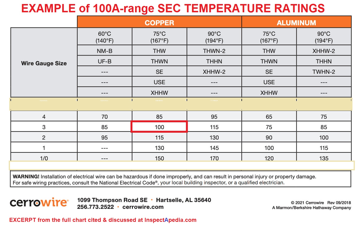
An example of #1 copper and aluminum wire ampacity ratings in the 100A range, showing different temperature ranges and the codes telling you the temperature ranges is given below, courtesy of cerrowire.com - you can see the full chart at
CERROWIRE AMPACITY CHART (image file)
From your question:
I have a street lighting controller that is rated at 100 Amps
Field installed conductors shall be
60 degrees C, or
90 degrees C,
sized to 60 degrees C rating for 110 amps or less;
and 75 degrees C or 90 degrees C for 125 amps and above."
I agree that whoever wrote those instructions lives in a mental fog and was unable to write clear, intelligible, unambiguous instructions.
I THINK what they're trying to say is
your wires can have a temperature rating of 60C or 90C
your wire can have a temperature rating of 60C if your control panel is 100A or less (yours is 100A)
your wire should have a rating of 75C OR 90C if your panel is 125A or higher (this is not your case)
The voltage drop for the wire bringing power to your control panel is figured by the run length of your SEC wire to to the panel
Separately, you will want to look at the length of your run from panel to each street light and to size those wires properly as well.
You can see that to meet the 60C requirement for a 100A panel you'd start (before increasing wire size for a longer run)
that
There are NO Cerrowire copper wire products rated for 60C in the 100A current range - the most you'd find is that #1 NM-B UF-B that can deliver up to 95A - too small
InsteadYou'd have to use #3 - 75C Copper THW THWN SE USE or XHHW wire to get 100A
Question: at what circuit length do I need to increase the wire size to allow for voltage drop?
2016/02/09 JD said:
What size wire do i need to run from a 200 amp pole service to a house 450 feet away?
Reply: crude rule of thumb: up one size for each 100 ft. of run
The voltage drop in a wire run has to remain within code limits, that's how we get to larger wire sizes for long runs. There are online voltage drop calculators for which of course you need to plug in wire size, type, length, and the electrical load or current.
However many electricians simply jump up one wire size for each 100 feet of run length.
A more engineering approach is cited at the Mike Holt's electrical forum where a reader says as an engineer he calculates the voltage drop (and thus the need for a larger wire size) when the run length of the circuit exceeds voltage rating of the circuit.
If we try this approach, for a 15A copper wire circuit using #14 copper wire in a typical household 120V circuit, if the circuit length exceeds 120 ft. the voltage drop must be calculated (or "considered").
This gives a result close to the first rule of thumb that argued just increase the wire size one step for each 100 ft. of run.
For a costly SEC run it would be smart to have your engineer calculate the actual voltage drop for the actual length and choose the larger wire size accordingly.
Voltage drop is not discussed at length in the U.S. NEC, except in Article 647 that addresses "Sensitive Electronic Equipment". There, the U.S. National Electrical Code PP 674.4. Wiring Methods, Paragraph (D) Voltage Drop states:
(D) Voltage Drop. The voltage drop on any branch circuit shall not exceed 1.5 percent. The combined voltage drop of feeder and branch-circuit conductors shall not exceed 2.5 percent. - 2002 NEC Article 647.4(D)
Watch out: "rule of thumb" approaches to electrical wiring may produce unsafe results, particularly where higher voltages or service entry wiring questions are involved.
And as we suggest above, using a rule of thumb on SEC wiring may also produce unnecessary costs. In general, voltage drop is a particular concern in low voltage wiring systems (such as 12V or 24V solar systems) while maximum current carrying capacity is a greater concern in higher voltage systems (such as a 120V residential circuit).
...
Continue reading at SE CABLE & WIRE SIZES FOR LONG RUNS or select a topic from the closely-related articles below, or see the complete ARTICLE INDEX.
Or see SE CABLE SIZES vs AMPS FAQs - questions & answers posted originally at the end of this page.
Or see these
Recommended Articles
- AMPS VOLTS DETERMINATION - home
- AMPS, LIMITING FACTORS
- AMPS & SEC SIZES
- AMPS & VOLTS, DETERMINE VISUALLY
- AMPS MEASUREMENT AUTOMOTIVE DC
- AMPS MEASUREMENT METHODS
- AMPACITY, MAIN DISCONNECT
- DEFINITIONS AMPS VOLTS WATTS
- ELECTRIC METERS & METER BASES
- ELECTRIC MOTOR HORSEPOWER & CIRCUIT WIRE SIZE
- ELECTRICAL PANEL AMPACITY
- VOLTAGE at the SEC
- UNDERGROUND SERVICE LATERALS
- ELECTRICAL WIRE TYPES CODES USES
- GROUND SYSTEM INSPECTION - home
- SAFETY for ELECTRICAL INSPECTORS - home
- SE CABLE & BRANCH CIRCUIT WIRE SIZES vs AMPS
- SE CABLE & WIRE SIZES FOR LONG RUNS
- SERVICE ENTRY WIRING & AMPACITY - wire sizes for main service entry
- SIZE of WIRE REQUIRED for ELECTRICAL RECEPTACLES - for receptacle circuits and similar wiring situations
- VOLTS / AMPS MEASUREMENT EQUIP
Suggested citation for this web page
SE CABLE & BRANCH CIRCUIT WIRE SIZES vs AMPS at InspectApedia.com - online encyclopedia of building & environmental inspection, testing, diagnosis, repair, & problem prevention advice.
Or see this
INDEX to RELATED ARTICLES: ARTICLE INDEX to ELECTRICAL INSPECTION & TESTING
Or use the SEARCH BOX found below to Ask a Question or Search InspectApedia
Ask a Question or Search InspectApedia
Questions & answers or comments about electrical wire sizes, diameters, and ampacity ratings.
Try the search box just below, or if you prefer, post a question or comment in the Comments box below and we will respond promptly.
Search the InspectApedia website
Note: appearance of your Comment below may be delayed: if your comment contains an image, photograph, web link, or text that looks to the software as if it might be a web link, your posting will appear after it has been approved by a moderator. Apologies for the delay.
Only one image can be added per comment but you can post as many comments, and therefore images, as you like.
You will not receive a notification when a response to your question has been posted.
Please bookmark this page to make it easy for you to check back for our response.
Our Comment Box is provided by Countable Web Productions countable.ca
Citations & References
In addition to any citations in the article above, a full list is available on request.
- Miller, Charles R., "Sizing Conductors, Part V, Ambient Temperature Correction Factors", October 2011, Electrical Contractor Magazine, Retrieved 11/16/14 original source: http://www.ecmag.com/section/codes-standards /sizing-conductors-part-v
- [1] "Thermostat Wire", Southwire Corporation, OEM Division, One Southwire Drive, Carrollton, Georgia 30119, Website: southwire.com/
Applicable Standards for thermostat wiring:
150 Voltage rating per NEC® Article 725
ETL listed to UL 13
Meets UL 1581 Vertical Tray Flame Test (FT-1)
Type CL2
Web search 12/14/2011, original source: http://www.southwire.com/ProductCatalog/XTEInterfaceServlet?contentKey=prodcatsheetOEM112 - The Original Authors: Alan Carson is an ASHI Member, national home inspection educator, author and building failures researcher in Toronto, Ontario. Daniel Friedman, an original author of this article and the editor and producer of InspectAPedia where this article now appears is an ASHI Member, first ASHI Technical Committee chairman, editor and publisher of the ASHI Technical Journal, licensed home inspector, educator, and building failures researcher in Poughkeepsie, NY. Robert Klewitz is a licensed professional engineer, a professional home inspector, an ASHI Member, and has served on the ASHI Technical Committee as well as in other ASHI activities. His practice is in Issaquah, WA.
- Mark Cramer Inspection Services Mark Cramer, Tampa Florida, Mr. Cramer is a past president of ASHI, the American Society of Home Inspectors and is a Florida home inspector and home inspection educator. Mr. Cramer serves on the ASHI Home Inspection Standards. Contact Mark Cramer at: 727-595-4211 mark@BestTampaInspector.com
- John Cranor [Website: /www.house-whisperer.com ] is an ASHI member and a home inspector (The House Whisperer) is located in Glen Allen, VA 23060. He is also a contributor to InspectApedia.com in several technical areas such as plumbing and appliances (dryer vents). Contact Mr. Cranor at 804-873-8534 or by Email: johncranor@verizon.net
- Daniel Friedman - InspectAPedia® Website Author/Editor
- Douglas Hansen, Robert Stead. Mark Cramer. Photographs: Daniel Friedman.
- N. Srinivasan, MSEE, is a senior member of IEEE with 30 years experience in the electrical industry. Mr. Srinivasan is in Vienna VA.
- Louis P. Babin generously contributed technical editing about the effects of doubling ampacity in an electrical circuit (September 2007)
- "Electrical System Inspection Basics," Richard C. Wolcott, ASHI 8th Annual Education Conference, Boston 1985.
- "Simplified Electrical Wiring," Sears, Roebuck and Co., 15705 (F5428) Rev. 4-77 1977 [Lots of sketches of older-type service panels.]
- "How to plan and install electric wiring for homes, farms, garages, shops," Montgomery Ward Co., 83-850.
- "Simplified Electrical Wiring," Sears, Roebuck and Co., 15705 (F5428) Rev. 4-77 1977 [Lots of sketches of older-type service panels.]
- "Home Wiring Inspection," Roswell W. Ard, Rodale's New Shelter, July/August, 1985 p. 35-40.
- "Evaluating Wiring in Older Minnesota Homes," Agricultural Extension Service, University of Minnesota, St. Paul, Minnesota 55108.
- In addition to citations & references found in this article, see the research citations given at the end of the related articles found at our suggested
CONTINUE READING or RECOMMENDED ARTICLES.
- Carson, Dunlop & Associates Ltd., 120 Carlton Street Suite 407, Toronto ON M5A 4K2. Tel: (416) 964-9415 1-800-268-7070 Email: info@carsondunlop.com. Alan Carson is a past president of ASHI, the American Society of Home Inspectors.
Thanks to Alan Carson and Bob Dunlop, for permission for InspectAPedia to use text excerpts from The HOME REFERENCE BOOK - the Encyclopedia of Homes and to use illustrations from The ILLUSTRATED HOME .
Carson Dunlop Associates provides extensive home inspection education and report writing material. In gratitude we provide links to tsome Carson Dunlop Associates products and services.
 | HOME | ABOUT | ASK a QUESTION | CONTACT | CONTENT USE POLICY | DESCRIPTION | POLICIES | PRIVACY | |
| © 2024 - 1985 Publisher InspectApedia.com - Daniel Friedman | |||||||||