
InspectAPedia® FREE Encyclopedia of Building & Environmental Construction, Diagnosis, Maintenance & Repair |
Question? Just ask us! InspectAPedia
|
 Electrical ground inspection
How to Inspect Residential Electrical System Grounds, Ground Wiring, Grounding Conductors, Grounding Electrodes
- POST a QUESTION or COMMENT about how to inspect residential electrical wiring ground system, & about defects in electrical ground system wiring
Electrical ground system inspection procedures & checklists.
This document discusses procedures the inspection of the grounding system components of a building electrical system when performed by trained building inspection professionals, home inspectors, electrical inspectors, and electricians.
InspectAPedia tolerates no conflicts of interest. We have no relationship with advertisers, products, or services discussed at this website.
Guide to Inspecting Electrical Service Grounding Equipment for Defects
Here we define electrical ground, grounding, bonding, and earthing terms and explain why there are important differences among these words.
[Click to enlarge any image]
“Grounding”, article 250 in the NEC, is probably one of the most difficult of the often used articles. In 2005 article 250 became “Grounding and bonding”. In the 2008 NEC there has been a major revision in language, and phrases like “shall be grounded” have changed to “shall be connected to an equipment grounding conductor.”
Sketches above and at page top courtesy of Carson Dunlop Associates, a Toronto home inspection, education & report writing tool company [ carsondunlop.com ].
Watch out: improper electrical grounding at a building can cause or contribute to fire, electrical shock, even death. If you are not qualified / trained in working safely with electrical wiring, leave any suspect electrical circuits off and ask for help from a licensed electrician.
Article Contents
- DEFINITION of GROUINDING EQUIPMENT
- WHERE do Ground Wires Go?
- WATER PIPING GROUND BOND
- GAS PIPING GROUND BOND
- GROUND WIRE SIZE TABLE
- GUIDE to INSPECTING ELECTRICAL GROUND SYSTEMS
- ELECTRICAL SERVICE GROUNDING CHECKLIST
- ELECTRICAL SERVICE GROUND TEST PROCEDURES
Also see DEFINITIONS of ELECTRICAL GROUND, Grounding Electrode, Grounding Conductor, Grounded Conductor, Ground Wire, Neutral Wire, Ground Rod, for definitions of these confusing electrical terms.
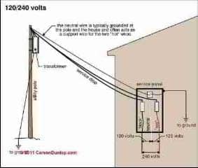
Why we need electrical grounding
The grounding system at a building provides an easy path for electricity to flow to earth should a problem, such as a short circuit, occur.
Allowing current to flow to earth through the ground system helps assure that a circuit breaker will trip or fuse will blow should a problem occur. Properly operating these overcurrent devices help prevent fire and shock.
Should an electrical fault occur where no ground path is present, the electrical potential is just sitting there waiting for a person to come along, touch some component of the system, and by accidentally providing a path to earth through their body, receive a burn or potentially fatal shock.
Sketch courtesy of Carson Dunlop Associates, a Toronto home inspection, education & report writing tool company [ carsondunlop.com ].
Details of why we need grounding, and definitions of electrical grounding and electrical bonding (what's the difference between these two terms) can be read at Why Grounding is Needed.
Bud, a master electrician from Minnesota has offered these important clarifications:
"Grounding" has 2 main functions.
One is to provide a path to trip a breaker in the event of a 'short' as in the text above. That function relies on a "ground"-to-neutral connection required at services in the US (the "main bonding jumper"). The path is (branch circuit ground wire) to (N-G bond at the service) to (service neutral) to (utility power transformer).
This path *must* be metallic back to the power transformer to provide low resistance to trip a circuit breaker. This function will work even if the service is not connected to earth. And the NEC *does not allow* earth to be used as part of this path.
One reason is the resistance of an earth path is too high. Assume the earthing is only through a ground rod and the rod has a quite good 10 ohms resistance to earth. Further assume there is a 'short' connecting hot to "ground".
The current to earth will be 12A. There is a good chance this won't even trip a 15A circuit breaker. If the circuit is loaded the breaker will trip, but after a significant time delay. In the mean time, the "ground" potential with respect to the earth away from the ground rod will be 120V.
Note that if you are using the earth as in the quote above, the path is not just into the earth. It is back to the power source, and also depends on the earth connection at the power transformer.
This would be better termed a *bonding* function.
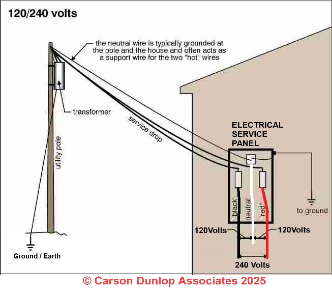
Carson Dunlop Associates' sketch shows how the electrical current in a building can find its way to earth by way of the electrical grounding system. But as you may want to read in
our case study of loss of all ground connections at a building, don't assume that the current will always find its way to earth.
Loss of electrical ground at a building is extremely dangerous and risks electrocution.
Some discussion points about electrical grounding are listed just below.
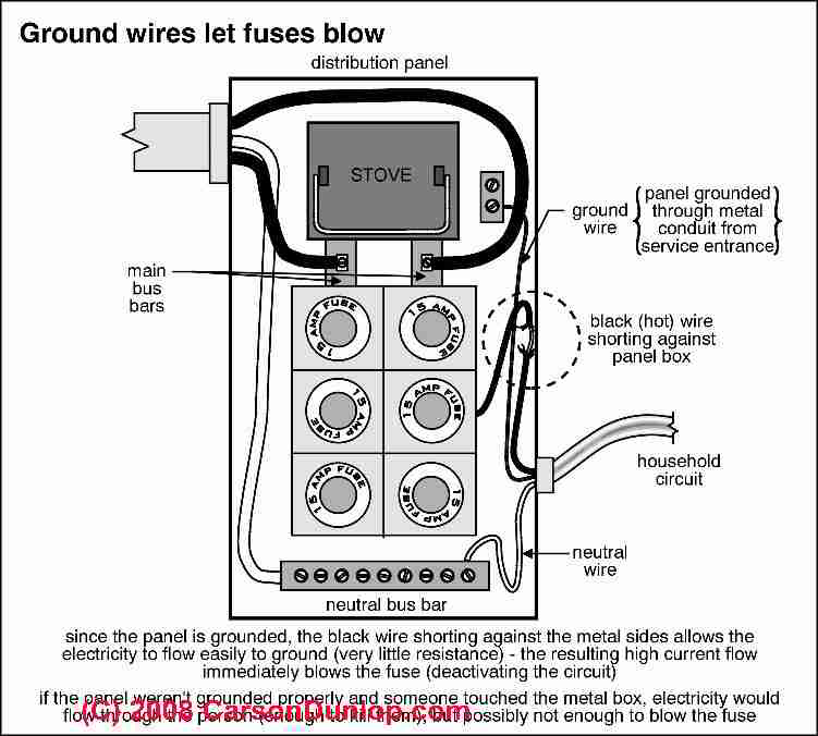
- Required for safety, lets fuses blow
- Example: toaster falls into metal sink
- Grounding Electrode Conductor wire from service equipment to
- House plumbing (grounds the plumbing)
- Entering metal water pipe (grounds the system)
- Grounding Electrode (two now recommended)
- Continuous, no splices, meter bypass
- Copper ground wires and grounding conductor (corrosion resistant)
- Aluminum - insulated solid conductor (See ALUMINUM WIRING HAZARDS & REPAIRS and
also ALUMINUM GROUND WIRES) - Aluminum - insulated multi-strand
- Aluminum - bare vs. insulated (risk of corrosion, break in wire, loss of safe grounding - illustrated below)
What is Meant by the "Grounding Equipment " in a Building?
As Carson Dunlop's sketch shows, the grounding equipment includes wires which bond the ground and neutral bus in the main electrical panel with an outdoor component that conducts electricity to the earth (ground).
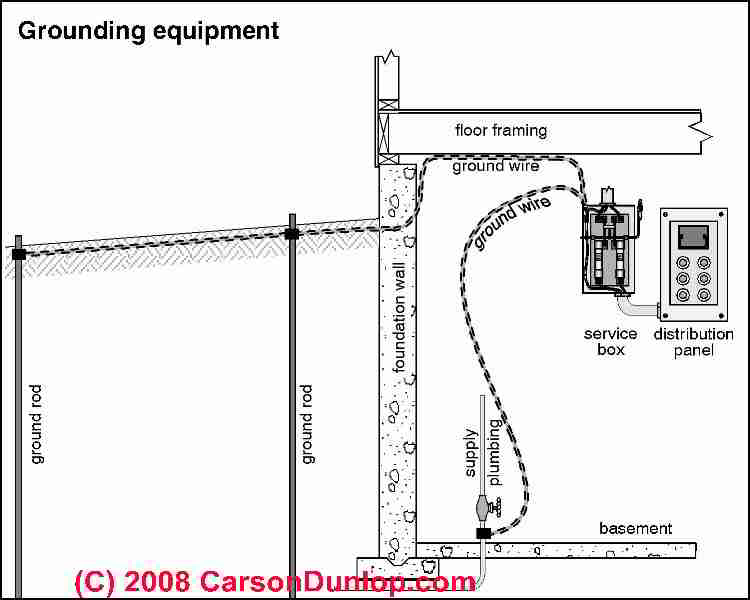
The outdoor component may be grounding electrodes (ground rods), or in some jurisdictions a metal water pipe or possibly other metal components.
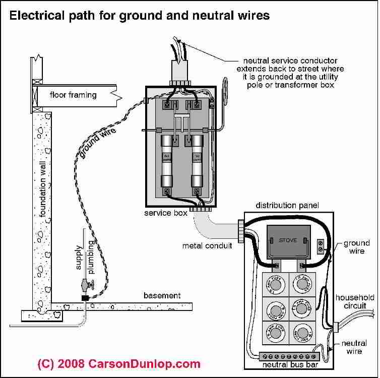
Where do Ground Wires Go?
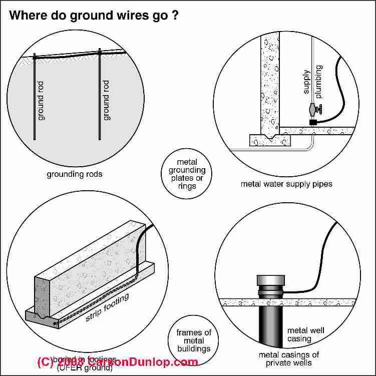
As Carson Dunlop Associates' sketch shows here, from the main electrical panel a grounding conductor connects to:
- a pair of grounding electrodes,
- a metal water pipe entering the building from outside,
- a strip footing which contains metal in contact with the earth
- to the metal casing of a private well
Why is Building Water Supply Piping Connected to the Ground System?
The NEC (section 250-81 through 250-83) requires that the electrical system connected to all of the following, if available for grounding purposes:
- metal frame of building [if the building has metal framing]
- concrete encased electrode (rod, pipe, plate, braided wire)
- ground ring
- metallic water pipe with 10 lineal feet in contact with earth
The reason we ground in-building plumbing is not to provide an additional grounding conductor in a building but to ground the plumbing.
Picture someone knocking a toaster into a stainless steel sink or into any sink with a metal drain and drain piping.
If the sink and piping are grounded the fuse or breaker will blow. If not, the system is waiting to electrocute the building occupant when s/he touches the live water/toaster in the sink and perhaps a nearby metal faucet, radiator, or other component that is ultimately connected to earth.
Similar hazards exist at other building locations such as basement laundry equipment & sinks, at building tubs and showers, etc.
In a properly-wired building, the grounding conductor and bonding system do not normally carry current, and would not be blamed for copper pipe pinholing etc. The grounding system is intended to conduct electrical current only in the event of a fault or emergency [such as a lightning strike or a hair dryer dropped into the bath tub or sink].
Details about the causes of copper pipe pinhole leak complaints are
at COPPER PIPE PINHOLE LEAKS, Pinhole Leaks: cause, cure, prevention
NEC Citations on grounding water piping
- NEC 250.50 "All grounding electrodes as described in 250.52(A)(1) through (A)(6) that are present at each building or structure shall be bonded together to form the grounding electrode system."
- 250.52(A)(1) Metal Underground Water Pipe - any connection to the water pipe must be within 5 feet of it entering the structure
- 250.52(A)(1) Water pipe electrode to be supplemented by another type of electrode (2) through (6) [listed just below]
- 250.52(A)(2) Metal Frame of Building or Structure grounding requirements
- 250.52(A)(3) Concrete-Encased Grounding Electrode
- 250.52(A)(4) Ground Ring requirements
- 250.52(A)(5) Rod and Pipe Grounding Electrodes
- 250.52(A)(6) Plate Electrodes (7)(B): Gas lines and aluminum electrodes are not permitted
- 250.53(D)(2) Supplemental Grounding Electrode Required,
Gas Piping May Need to Be Bonded to the Electrical Ground System

In some communities, as Carson Dunlop Associates' sketch shows, the metal gas piping in a building must be bonded to the electrical ground system.
Bonding anything to the ground system, including metal gas piping, helps prevent an electrical spark that might otherwise result in an explosion in the case of a gas piping system.
The bonding of the gas piping to the building ground system is not the same thing as attempting to use the metal gas piping as the primary or only connection to earth in a building.
Table of Electrical Ground Wire Sizes
| Ground Wire Gauge CU (Copper) - wire size | Electrical Service Size |
| #8 | to 100A |
| #6 | to 125A |
| #4 | to 165A |
| #3 | to 200A |
See DEFINITIONS of Electrical Ground, Grounding Electrode, Grounding Conductor, Grounded Conductor, Ground Wire, Neutral Wire, Ground Rod, for definitions of these confusing electrical terms.
More details about electrical grounding can be read
at ELECTRIC SERVICE GROUNDING SYSTEM INSPECTION and
and at OLD HOUSE ELECTRICAL SYSTEMS.
Also, see details about electrical grounding at ELECTRICAL CIRCUITS, SHORTS,
and at ELECTRICITY BASICS, HOW IT WORKS.
At ALUMINUM GROUND WIRES we discuss proper repair of aluminum ground wires found in solid conductor branch circuit wiring.
Guide to Inspecting Electrical Service Grounding Equipment
Readers should see our complete electrical ground inspection information
at ELECTRICAL GROUND SYSTEM INSPECTION
This article series describes procedures for safe and effective visual inspection of residential electrical systems including electrical panels and other components, when the inspection is conducted by trained building inspection professionals, home inspectors, electrical inspectors, and electricians.
This information was presented by Daniel Friedman - InspectApedia.com, at & discussed by the Hudson Valley chapter of the American Society of Home Inspectors - HVASHI Seminar 12 Sept 2002, Updated April 2006, April 2009.
Carson Dunlop Associates' sketch at page top shows where the electrical inspection starts at a residential property.
Table of Electrical Ground Wire Sizes Required by Electrical Service Size
| Ground Gauge CU (Copper) | Service Size |
| #8 | to 100A |
| #6 | to 125A |
| #4 | to 165A |
| #3 | to 200A |
Electrical Service Grounding Defects & Conditions to Check For During an Electrical Inspection
Here are the Most-Common Electrical Service Grounding Defects & Conditions

- not found in sub panel feeder (a)
- attached to plastic pipe (b)
- attached to abandoned pipe (b)
- spliced (b)
- loose or missing connections (a) or (b)
- inaccessible connections
- no water meter bypass or other dielectric plumbing fitting bypass (bonding jumper)
- local grounding electrode conductor not found in main panel
- ground bond between neutral and ground and panel enclosure not found in the main panel
- no water meter/water shutoff valve bypass (bonding jumper) (a)
- neutral (the grounded conductor) bonded to ground downstream of box (or upstream)
- neutral bus not bonded to the ground bus (equipment grounding conductors & ground bus) at main panel
- main panel not bonded to grounding electrode conductor and ground bus
- undersized grounding electrode conductor wire
- ground rod (grounding electrodes) cut off or short (or only one grounding electrode connection at new construction)(b)
- corroded grounding electrode conductor (b) - More about the galvanic scale and corrosion between dissimilar metals is
at GALVANIC SCALE & METAL CORROSION. - loose or missing grounding electrode conductor clamp at the grounding electrode (b)
- loose or missing bonding jumper clamp(s) such as at a water meter or water pipe (b)
- bare aluminum grounding electrode conductor exposed to corrosion (b) - More about the galvanic scale and corrosion between dissimilar metals is
- at GALVANIC SCALE & METAL CORROSION.
- neutral bonded to the equipment grounding conductor (the ground wire) in sub panel or junction box (a)
- neutral not bonded to ground at the main service panel (b)
- main panel not bonded to ground wire (b)
Notes on types of defects courtesy of Arlene Puentes. Sketch courtesy of Carson Dunlop Associates, a Toronto home inspection, education & report writing tool company [ carsondunlop.com ].
(a) Equipment grounding conductor defect
(b) Grounding electrode conductor defect
More about the galvanic scale and corrosion between dissimilar metals is
at GALVANIC SCALE & METAL CORROSION.
What Other Defects Should We Check for in an Electrical Grounding System?
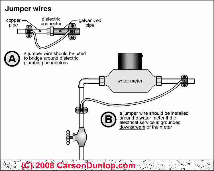
- Jumper wires to ground plumbing:
As Carson Dunlop Associates' sketch shows at (A), if the building plumbing includes DIELECTRIC FITTING CODES or non-conductive sections of piping (such as plastic piping) then the building plumbing system may not be safely grounded.
Spelling note that may help some web searches: it's not dialectic pipe fittings, but dielectric pipe fittings.
A jumper wire is installed to assure that the building metal plumbing pipes are safely grounded to earth.
The purpose of the ground jumper is to ground the building plumbing, not to use the building plumbing as a grounding system.
That is to say, we're making the plumbing safe, we're not using it to provide a ground for the electrical system.
The Dialectic Philosophy of Dielectric Electrical Separation of Materials
Thanks to reader Bill O'Reilly (not that one) for the following excellent comment.
7/21/2014 Bill O'Reilly (not that one) said:
There's a spoonerism in the "Electrical ground inspection" article in the phrase ..."if the building plumbing includes dialectic fittings"... Dialectic fittings could be decorative, but wouldn't serve the intended function.
The word dialectic should be dielectric.
A dialectic is a form of formal argument first popular in the golden age of greece. [Dialectic is defined as The art of investigating or discussing the truth of opinions, inquiry into metaphysical contradictions and their solutions - Ed.]
A dielectric separates two electrically conducting materials so that they can be at two different potentials, more formally an electric di-pole. In the formal sense, a dielectric can be a solid (e.g. glass, porcelain, nylon, polyvinylchloride), a liquid (e.g. oil), a gas (e.g. dry air, sulfur hexafluoride), or a vacuum, which is nothing at all.
In the particular sense of the phrase's context, the dielectric blocks the flow of electrons between the dissimilar metals, thus preventing the flow of dissolved ions from the water to the cathode and (metallic) ions from the anode into the water.
More information on Dielectric fittings
- DIELECTRIC FITTING CODES
- GALVANIC SCALE & METAL CORROSION
- GALVANIZED STEEL WATER PIPING
- GALVANIZED IRON PIPE INSTALLATION
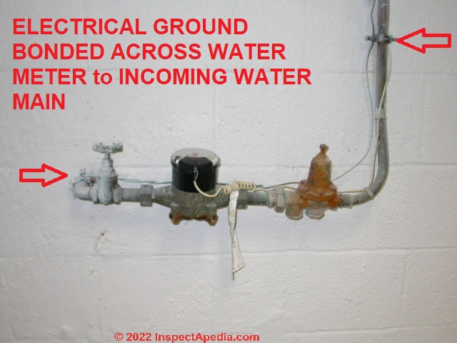
- Grounding system jumper wire around the water meter:
as the same sketch shows at (B), if the building water main piping is being used as a source to provide a ground for the electrical system, then the main ground wire between the electrical panel and the water piping should be clamped on both sides of the water meter.
In this case the building water supply piping is being used as part of the electrical grounding system, and we need to be sure that that connection to earth is not interrupted by non-conductive components of the water meter itself.
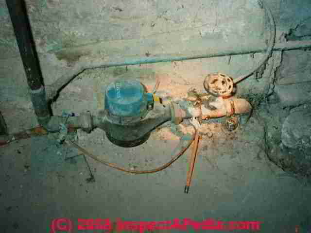
In our photo you can see that the meter bypass jumper has become disconnected (where our flashlight is shining) and that the system ground wire was also spliced.
We bond the building water pipe to the grounding wire on the street side of the water meter
to be sure that the building electrical system is grounded to earth.
We bond the building water pipe to the grounding wire on the building-side of the water meter
to be sure that the building water piping is safely grounded too.
This grounding wire should be continuous,
through both pipe clamps securing it to the water piping before and after the water meter, and continuing into the main electrical panel where it joins the ground bus and neutral bus.

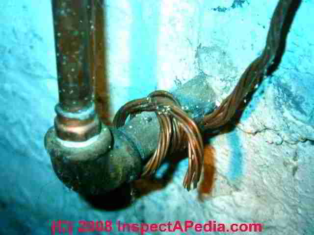
- Corroded copper grounding wires
can also be unreliable as our photo shows.
We would be reluctant to trust this connection for the building grounding system.
More about the galvanic scale and corrosion between dissimilar metals is at
GALVANIC SCALE & METAL CORROSION.
Electrical Code Requirements for Grounding Water Pipes: NEC Citations on grounding water piping
- NEC 250.50 "All grounding electrodes as described in 250.52(A)(1) through (A)(6) that are present at each building or structure shall be bonded together to form the grounding electrode system."
- 250.52(A)(1) Metal Underground Water Pipe - any connection to the water pipe must be within 5 feet of it entering the structure
- 250.52(A)(1) Water pipe electrode to be supplemented by another type of electrode (2) through (6) [listed just below]
- 250.52(A)(2) Metal Frame of Building or Structure grounding requirements
- 250.52(A)(3) Concrete-Encased Grounding Electrode
- 250.52(A)(4) Ground Ring requirements
- 250.52(A)(5) Rod and Pipe Grounding Electrodes
- 250.52(A)(6) Plate Electrodes (7)(B): Gas lines and aluminum electrodes are not permitted
- 250.53(D)(2) Supplemental Grounding Electrode Required,
List of Still More Electrical Grounding System Checkpoints:
- Confirm that a grounding connection to earth is present:
New electrical installations should have two grounding electrodes at the building; older homes may have only one grounding electrode, or no ground rods but a connection to an incoming water pipe, or in the worst case, no local ground at all.
You may have to look closely even to find the grounding electrode, but following the ground wire should lead to it if an electrode is present. Photo courtesy of Tim Hemm.
- Confirm that grounding is present in all sub panels:
Check for grounding not found in sub panel feeder cable - Follow building piping
to be sure that its ground path is electrically continuous. A main ground wire attached to plastic pipe is completely ineffective.

- Corroded aluminum electrical ground wire
aluminum ground wires corrode through and ground can be lost. That's why new electrical work that uses aluminum ground wires should be performed only using wires that are insulated.
We've seen this happen, as shown in our picture at left, leading to loss of the local building ground connection when the bare aluminum ground wire was touching the edge of a masonry block foundation.
Moisture in the foundation wall and probably the chemistry of the masonry block, mineral salts left by water entry, and the aluminum wire itself led to through-corrosion of the ground wire.
At ALUMINUM GROUND WIRES we discuss proper repair of aluminum ground wires found in solid conductor branch circuit wiring.
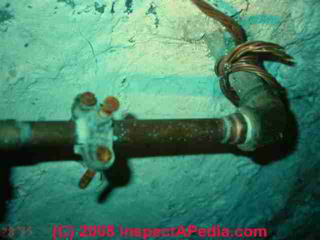
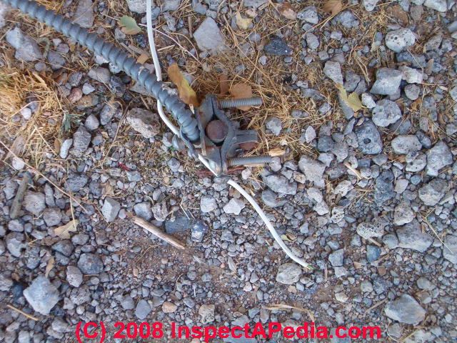
- Loose or missing ground connections securing the ground wire to a water pipe or to a grounding electrode.
As you can see in our photo, someone just skipped the clamp intended to secure the copper ground wire to the incoming water pipe, and left it wrapped around the pipe quite loosely.
Often we find this condition when someone needed to temporarily disconnect the ground wire, perhaps during a plumbing repair.
The plumber may not have taken seriously the need to re-connect the building ground system.
No one may notice this problem because even if this ground connection is totally ineffective, the building may be still grounded through the service entry ground wire. As we demonstrated
at DOUBLE FAULT, LOSS OF ELECTRICITY, it's not safe to rely on just the utility company's ground connection.
- False Grounds
are wiring "tricks" that can make an electrical circuit appear to be properly grounded when it is not. A conventional plug-in circuit tester will not find false grounds, as we explain
at FALSE GROUND at Receptacles where we provide details. - False Neutrals
are wiring "tricks" that make an electrical circuit appear to have a good neutral wire connection when it does not. Since the ground wire or ground path may have been (improperly) used for this, we illustrate an example of a false neutral using a ground path just below, and we discuss this foul-up in detail in the FALSE NEUTRAL link given just below.

The ground system wiring is for emergency-use only - it should never be wired so as to carry current during normal operation.
(E.g. This occurs if a
sub panel bonds the neutral to ground wires).
We've found cases in which someone used the ground path to complete an electrical circuit because the neutral wire was broken somewhere that could not be found.
As a result, the ground path was electrically live when it should not have been, leading to an electric shock.
In our photo at left, someone used telephone wire to connect the neutral side of this electrical receptacle to the receptacle's steel mounting strap, knowing that that would in turn connect the neutral side of the receptacle to the steel junction box and through it, to the armored BX electrical cable, forming an electrical path back to the main electric panel.
We discuss this crazy wiring in more detail
at FALSE NEUTRAL CONNECTIONS.
Indeed this got the receptacle "working" by using the ground path in the system after the original neutral path had been lost.
We were working on renovating the home where we found this condition.
How did we find it? We were replacing two-prong un-grounded receptacles with grounded devices.
We turned off electrical power to this circuit and began working on it.
When our assistant plugged in and began using a vacuum cleaner in the same room we got an electrical surprise - a shock while touching the BX cable!
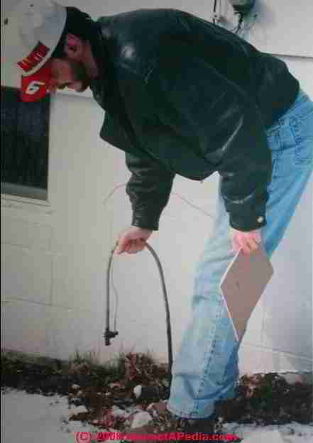
- Grounding Electrode Cut Off, Short, or Inadequate - see below

- Ground rod cut off or short
don't assume that because you see a grounding electrode that it has been properly installed. If the installer hit rock and couldn't drive the rod fully into the soil s/he may have cheated and simply cut off the top of the rod.
Grounding electrodes in some locales have an embossed code on their upper end - if the rod was cut off the embossed letters will be missing. If a grounding electrode cannot be fully driven into the soil the electrical code provides procedures for driving the electrode in cut-sections to achieve sufficient total earth contact.
As we and our inspection client discovered (photos above), the bent-over grounding electrode made us wonder what was happening. When the grounding electrode was just nudged with a toe, it fell over. Our client was kind enough to demonstrate just how ineffective this electrical ground system was, thanks to someone's shortcut.
- Grounding wire not found in main electrical panel
- Grounding wire not found in sub panel feeder
- Inaccessible connections to the grounding system (can't be inspected or maintained)
- Main electrical panel enclosure not bonded to grounding system
- Main ground wire attached to abandoned pipe
such as a metal water pipe that used to run underground to a remote well but which, now that it's abandoned in the building, may have been also cut off outside of the building, or may have rusted away - Neutral wire bonded to ground wire
anywhere downstream of the main electrical panel, in a sub panel -
see Case History: LOSS of NETURAL SHOCKS HOMEOWNER - Neutral bus not bonded to ground bus in the main electrical panel
- Spliced ground conductor
between the electrical panel and the ground rod or water pipe is improper (the connection may be unreliable) - Undersized ground wire -
see TABLE of GROUND WIRE SIZES
Readers should also
see DEFINITIONS of Electrical Ground, Grounding Electrode, Grounding Conductor, Grounded Conductor, Ground Wire, Neutral Wire, Ground Rod, for definitions of these confusing electrical terms.
SYSTEM GROUNDING - A Summary of Inspecting Residential Electrical System Grounding for Defects
- Electrical grounding improves building electrical safety because
it provides better path for current than a person, blows fuse/breaker, dissipates static, may dissipate lightning - Example of a potential shock waiting for someone:
loose black wire in a metal junction box touches the side of the box. If the electrical box is connected to ground lots of current will flow (this is a short circuit) and the fuse or circuit breaker protecting the electrical circuit will blow or trip.
But if the electrical box is not grounded, current flows through a person when the electrical box or anything connected to it (electrically) is touched, if the person has the bad luck to also be herself grounded (say by touching building piping or standing on a wet floor).
While we have frequently updated and added to the material, in its original form this information was presented by Daniel Friedman - InspectAPedia.com, at the Hudson Valley chapter of the American Society of Home Inspectors - HVASHI Seminar 12 Sept 2002, Updated April 2006, February 2013, March 2014, July 2014, December 2014
Watch out: for safety, also
review SAFETY HAZARDS & SAFE ELECTRICAL INSPECTION PROCEDURES for Inspectors examining Residential Electrical Systems
Testing the Local Electrical Ground
Reader Question: how do I test my electrical system ground system components?
4 June 2015 Bill Said: I am replacing my service panel,in my condo, and the conduit running from the sub panel is being used as the earth ground. How can I test this ground?
Reply: US NEC & IEEE codes & standards for electrical ground testing
Bill,
When the conduit is being used as the earth ground it must meet certain UFER specifications and impedence requirements. Below is a general answer discussing local electrical ground electrode testing.
Before even testing an electrical ground system and its components be sure that you have installed the proper number and type of grounding conductors, connectors, and local grounding electodes.
See ELECTRICAL GROUND REQUIREMENTS
There are two frequently-used approaches for testing the efficacy of an earth-electrode grounding system. These tests should be performed when the grounding electrodes are first-installed and might be repeated later for a variety of reasons.
The first is the Three-Point Grounding System Test also referred to as the Fall of Potential Grounding Test and the second is the Induced Frequency Test or Clamp-On Method of Electrical Ground Test.
Watch out: do not attempt to perform ground system tests if you are not trained and equipped to do so. Making a mistake could result in or contribute to a subsequent fire, injury, or death. Similarly, don't rely on such tests if they were not performed by a qualified expert electrician or electrical engineer.
To perform the three-point-grounding-system test the electrical system is isolated from the power utility through ALL of its connections (i.e. current conductors and the electrical utility's ground or neutral conductor).
To perform the induced frequency test the power is left on and connected to the electrical power utility's system. This second test is suitable only for small electrodes and is discussed by E&S Grounding (cited below) as well as our other references.
High Impedance Safety Standard
Watch out: If a local ground is isolated from the electrical company's ground (neutral wire in the panel) and does not conduct electricity or shows high resistance (or more generally, high impedence) it is not safe. How much is "high impedence" when testing an electrical ground system at a building?
The NEC specifies 25 ohms as an acceptable limit for electrode impedance.
The IEEE Standard 142 Recommended Practice for Grounding of Industrial and Commercial Power Systems (“Green Book”) suggests a resistance between the main grounding electrode and earth of 1 to 5 ohms for large commercial or industrial systems.
- Fluke Corporation, "CHECKGING GROUND ELECTRODE impedence for commecial, industrial, and residential buildings", [PDF] Fluke Corporation cited in detail below.
Watch out: this test needs to be performed by a trained electrician as there are shock and electrocution hazard risks. As Fluke and other experts point out, to perform testing of the local grounding electrode it must be disconnected from the building. The ground testing instructions that we cite below include additional important safety warnings and procedureal details from which we excerpt.
Ground Impedence Testing
From reading the literature our opinion is that this test is technically difficult, requires expertise, and should not be attempted by a homeowner nor by anyone else who lacks the necessary expertise.
Here is an excerpt from Fluke Corporation, a producer of a wide range of electrical test equipment:
There are two types of ground impedance testers. Three and four point ground testers and clamp-on ground testers. Both types apply a voltage on the electrode and measure the resulting current.
A three or four-pole ground tester combines a current source and voltage measurement in a “lunch box” or multimeter-style package. They use multiple stakes and/or clamps.
Ground testers have the follwing characteristics:
- AC test current. Earth does not conduct dc very well.
- Test frequency that is close to, but distinguishable from the power frequency and its harmonics. This prevents stray currents from interferring with ground impedance measurements.
- Separate source and measure leads to compensate for the long leads used in this measurement.
- Input filtering designed to pick up its own signal and screen out all others.
Clamp-on ground testers resemble a large clamp meter. But they are very different because clampon ground testers have both a source transformer and a measurement transformer.
The source transformer imposes a voltage on the loop under test and the measurement transformer measures the resulting current. The clamp-on ground tester uses advanced filtering to recognize its own signal and screen out all others. - Fluke Corporation (2018), cited in detail just below.
Grounding Electrode Testing Shortcut using the 62% Rule
Fluke Corporation describes a simplified grounding electrode test in which the technician drives additional spikes into the ground to permit several measurements fof impedence that are compared at different distances from the grounding electrode under test.
Measurements are made by connecting test leads to the grounding electrode, to a "current spike" driven at a specified distance "d" from the test electrode, and one to three "potential spikes" driven at a distance equal to 62% of distance "d".
Details are in several sources including a Fluke Corporation procedure we cite just below.
You may be able to use a shortcut if your test meets the following criteria:
- You are testing a simple electrode (not a large grid or plate)
- You can place the current stake 100 feet or more from the electrode under test
- The soil is uniform
Under these conditions you can place the current stake 100 feet or more from the electrode under test. Place the potential stake at 62 % of the distance between the current stake and the electrode under test and take a measurement.
As a check, take two more measurements: one with the potential probe 3 feet closer to the electrode under test, and one 3 feet farther away (see Figure 5 in Fluke's document). If you are on the flat portion of the fall-of-potential curve then the readings should be roughly the same and you can record the first reading as your resistance. - Op. Cit.
Standards & Procedures for Testing the Electrical Ground System

Above: an illustration from the US NBS 1918 procedure for electrical ground testing.
- Beyer, Wally, ELECTRICAL PROTETION GROUNDING FUNDAMENTALS [PDF] (1994), U.S. Department of Agriculture USDA REA Bulletin 1751F-802,
Note: See Appendix C: MEASUREMENT of SOIL RESISTIVITY p. 35 and Appendix D: MEASUREMENT of RESISTANCE TO GROUND p.48
Purpose:
To provide technical information for use in the design, construction and operation of REA borrowers' telephone systems. The basic factors affecting earth resistivity and grounding are discussed.
Information is also provided on the selection of an appropriate location for the installation of electrodes.
Further, techniques are presented for measuring soil resistivity and resistance to ground of an electrode. - EE Publishers, PRINCIPLES AND TESTING METHODS OF EARTH GROUND RESISTANCE [PDF], EE Publishers (Pty) Ltd P O Box 458 Muldersdrift 1747 South Africa, retrieved 2018/07/31, original source: http://www.ee.co.za/article/principles-testing-methods-earth-ground-resistance.html Contact Gerrit Barnard, Comtest,Tel 011 608-8520, gbarnard@comtest.co.za
- E&S Grounding Solutions, "HOW TO DO ELECTRICAL GROUNDING SYTEM TESTING", E&S Grounding Solutions, 703 Pier Avenue, Suite B174 Hermosa Beach, CA 90254 USA - accessed 2018/07/31, original source: http://www.esgroundingsolutions.com/how-to-do-electrical-grounding-system-testing/
- Fluke Corporation, CHECKING GROUND ELECTRODE IMPEDENCE FOR COMMECIAL, INDUSTRIAL, AND RESIDENTIAL BUILDINGS [PDF] Fluke Corporation, PO BOx 9090, Evrett WA, USA 98206, Tel U.S.A. (800) 443-5853, Fluke Europe, B.V., PO Box 1186, 5602 BD Eindhoven, The Netherlands, In Europe/M-East/Africa +31 (0) 40 2675 200 , In Canada (800)-36-FLUKE From other countries +1 (425) 446-5500 Website: http://www.fluke.com
- Peters, O.S., GROUND CONNECTIONS for ELECTRICAL SYSTEMS, Technologic Papers of the Bureau of Standards, No. 108, U.S. National Bureau of Standards NBS, S.W. Stratton, Dir., (20 June 1918), U.S. Department of Commerce, retrieved 2018/07/31, original source: https://nvlpubs.nist.gov/nistpubs/nbstechnologic/nbstechnologicpaperT108.pdf
In this document beginning in p. 146 you will find a deccription of TESTING of the electrical ground connections and an explanation of the basis for focus on electrical resistance rather than capacitance tests. - Weschler, GETTING DOWN to EARTH, A PRACTICAL GUIDE to EARTH RESISTANCE TESTING [PDF], Weschler Instruments 16900 Foltz Parkway Cleveland OH, 44149 USA Tel: 440 238-2550 - 800 557-0064 retrieved 2018/07/31, original source: http://www.weschler.com/_upload/sitepdfs/techref/gettingdowntoearth.pdf
Reader Comments, Questions & Answers About The Article Above
Below you will find questions and answers previously posted on this page at its page bottom reader comment box.
Reader Q&A - also see RECOMMENDED ARTICLES & FAQs
On 2021-01-30 by John Teague - does my house need a local ground if there is one outdoors at the utility company transformer?
If there is a ground from the transformer and the main disconnect does there need to be another one from the residential breaker box?
On 2021-01-30 - by (mod) - Yes a local ground MUST be provided
John:
Absolutely, yes the local ground MUST be provided; a key problem is with the portion of your question that reads:
If there is a ground from the transformer ...
The problem is that such a connection to the local panel can be interrupted for any of a number of reasons. It's not just theory; I've come across it in my own personal experience, with catastrophic consequences (shock, fire, death); since any one of us individuals is a nanoscopic sampling point moving through time, I figure that if one of us sees this failure of the utility company's ground, then it probably happens far more often than we realized.
Current electrical codes want two local grounds at every building's electrical system; that, too, testifies to the critical importance of this safety feature.
Please take a look at
LOST ELECTRICAL GROUND
https://inspectapedia.com/electric/Electrical_Ground_Lost.php
LOST NEUTRAL SHOCKS HOMEOWNER
https://inspectapedia.com/electric/Electrical_Neutral_Lost.php
and thank you again for the question; don't hesitate to post follow-up comments, questions, arguments.
On 2021-03-19 by Jim Navotney
@John Sundeen, I think the electrician was mistaken but it's always a good practice to bond all metal objects to the electrical ground.
On 2021-03-19 - by (mod) - good practice to bond all metal objects to the electrical ground
@Jim Navotney, thank you for adding that comment, it's really an important safety point.
We are particularly grateful when people are able to make comments that are well informed and safe, particularly on these electrical topics.
On 2020-04-09 by John Sundeen - grounding to metal water pipe - an "electrical well" impedes grounding?
If a system has a 3 guage copper wire running from a 200amp electrical panel to the main water supply metal pipe right where it is coming in from through a basement wall, one would think that should establish a good ground. However, there is one odd thing with a particular system.
The 3 guage wire enters a 1 inch diameter copper pipe just below the ceiling joists and runs down to the water main. This was probably done (57 years ago) to protect the ground wire.
Upon visual inspection an electrician commented that there should be a clamp connection between the ground wire and the copper pipe up by the joists. He stated that without the clamping, the pipe could create an electrical "well" that would impead the grounding. ( Just to aleaveate any doubt, there is no water well involved; the structure is on city water service.)
Why would this welling be created and why would it hurt the grounding?
On 2020-04-09 - by (mod) - there should be a clamp connection between the ground wire and the copper pipe
Thanks for the comment, John.
Unfortunately a lot of things that I once thought were obvious as one would think, experts explained I had got wrong.
For example, a metal water pipe is by no means an entirely reliable grounding connection for electrical systems.
- the piping may include a diaelectric fitting that isolates one section from another -
- the piping may convert to metal or other less-conductive materials
- the piping may not provide adequate total soil contact in depth as well as area
Therefore while there are important safety reasons for assuring that metal water piping in a building is electrically grounded (so knocking a toaster into the sink will trip a breaker or blow a fuse before we get electrocuted), current electrical codes require 2 electrical grounding electrodes at buildings (in new construction) and most inspectors won't accept a water pipe connection as the only system ground to earth.
I think your electrician was making sure that the ground path was continuous.
I have no idea what's meant by an "electrical well" - and wonder if the electrician, surely smarter than you or I on this topic, may not have been an English major and may not communicate perfectly.
Possibly he meant a "weld" that would, in the event of a severe current on the ground wire, melt materials at a point of contact and thus lose the electrical ground. I have seen that happen, resulting in house fire.
On 2015-03-30 by Anonymous - broken ground wire fdrom ground bus to "main disconnect"
Question? my ground wire going to the ground bar from my main disconnect was broken so i replaced it and i notice a small spark while connecting it then i proceed to take an ampreading on the wire and it showed 1.5amps is this a normal.
On 2015-03-30 - by (mod) -
Watch out: In most of the electrical system there is not normally current running on the grounding conductor.
I'm unclear on what ground wire is running from your main disconnect switch, and not wanting to risk killing a reader, am chicken to comment further.
On 2015-03-12 by Harold - how do we ground the electrical panel if there is a common water meter
Question? We live in a cooperative where there is no water meter in our unit there is 1 main meter that feeds several units. How do we properly ground the electrical panel?
On 2015-03-13 - by (mod) -
the plumbing should be grounded, including a jumper around the electrical meter, and the building should have one or perhaps two independent grounding electrodes.
On 2015-02-10 by Anonymous - how do we ground-bond plastic water pipes?
Bonding of plastic water pipes
On 2015-02-10 - by (mod) - we don't
Anon
We don't bond plastic water pipes - as they don't conduct electricity.
However as a separate concern (bonding water piping is different from using an incoming water main as a local electrical ground) I've warned elsewhere that an electrical system that is relying on metal water piping bringing water to the building, for example from a water main or from a well system, can become unsafe if that water piping is later replaced with plastic- as we no longer have a good connection to the earth through the piping. In any event, one or more local, driven grounding electrodes used to provide the local building ground are recommended and are required in some jurisdictions where previously we relied perhaps on a single buried water pipe.
...
Continue reading at ALUMINUM GROUND WIRES or select a topic from the closely-related articles below, or see the complete ARTICLE INDEX.
Or see ELECTRICAL GROUNDING FAQs - questions & answers posted originally at this article
Or see these
Recommended Articles
- DOUBLE FAULT, LOSS OF ELECTRICITY
- ELECTRICAL GROUND ERROR-CAUSED LEAKS - leaks in metal water pipes traced to improper grounding
- ELECTRICAL SERVICE ENTRY DAMAGE - service entry wire melts & shorts to ground
- GAS PIPING, FLEXIBLE CSST - lightning protection needed for flexible stainless steel tubing used as gas piping
- GROUND SYSTEM INSPECTION - home
- ALUMINUM GROUND WIRES
- CSST GAS PIPING SAFETY & PROTECTION
- DIELECTRIC FITTING CODES
- DOUBLE FAULT, LOSS OF ELECTRICITY
- ELECTRICAL BOX GROUND WIRING
- ELECTRICAL GROUNDING in OLDER HOMES
- ELECTRICAL GROUND DEFINITION
- ELECTRICAL GROUND CAUSED PLUMBING LEAKS
- ELECTRICAL GROUND DEFINITIONS
- ELECTRICAL GROUND INSPECTION SAFETY
- ELECTRICAL GROUND REQUIREMENTS
- FALSE GROUND at RECEPTACLES
- FALSE GROUND, BOOTLEG & FLICKERING LIGHTS
- GAS PIPING GROUND BOND
- GROUND SYSTEM REQUIREMENTS
- KNOB & TUBE WIRING
- LIGHTNING PROTECTION SYSTEMS
- LOST ELECTRICAL GROUND
- LOST NEUTRAL SHOCKS HOMEOWNER
- METAL SIDING ELECTRICAL GROUND?
- SERVICE GROUNDING DEFECTS
- SAFETY for ELECTRICAL INSPECTORS - home
Suggested citation for this web page
ELECTRICAL GROUNDING in OLDER HOMES at InspectApedia.com - online encyclopedia of building & environmental inspection, testing, diagnosis, repair, & problem prevention advice.
Or see this
INDEX to RELATED ARTICLES: ARTICLE INDEX to ELECTRICAL INSPECTION & TESTING
Or use the SEARCH BOX found below to Ask a Question or Search InspectApedia
Ask a Question or Search InspectApedia
Try the search box just below, or if you prefer, post a question or comment in the Comments box below and we will respond promptly.
Search the InspectApedia website
Note: appearance of your Comment below may be delayed: if your comment contains an image, photograph, web link, or text that looks to the software as if it might be a web link, your posting will appear after it has been approved by a moderator. Apologies for the delay.
Only one image can be added per comment but you can post as many comments, and therefore images, as you like.
You will not receive a notification when a response to your question has been posted.
Please bookmark this page to make it easy for you to check back for our response.
Our Comment Box is provided by Countable Web Productions countable.ca
Citations & References
In addition to any citations in the article above, a full list is available on request.
- [1] "Publication No. 37: Electrical Grounds - A Controversial Necessity", The State of Connecticut Department of Public Health Environmental Health Section, Private Well Program 450 Capitol Avenue, MS#51REC, PO Box 340308, Hartford, CT 06134 Phone: 860-509-7296, retrieved 2/7/13, original source: http://www.ct.gov/ [copy on file]
- See Definitions of Electrical Ground, Grounding Electrode, Grounding Conductor, Grounded Conductor, Ground Wire, Neutral Wire, Ground Rod, for definitions of these confusing electrical terms.
- More details about electrical grounding can be read at ELECTRIC SERVICE GROUNDING SYSTEM INSPECTION and ELECTRICAL CIRCUITS, SHORTS, and at OLD HOUSE ELECTRICAL SYSTEMS.
- At ALUMINUM GROUND WIRES we discuss proper repair of aluminum ground wires found in solid conductor branch circuit wiring.
- Mark Cramer Inspection Services Mark Cramer, Tampa Florida, Mr. Cramer is a past president of ASHI, the American Society of Home Inspectors and is a Florida home inspector and home inspection educator. Mr. Cramer serves on the ASHI Home Inspection Standards. Contact Mark Cramer at: 727-595-4211 mark@BestTampaInspector.com
- John Cranor [Website: /www.house-whisperer.com ] is an ASHI member and a home inspector (The House Whisperer) is located in Glen Allen, VA 23060. He is also a contributor to InspectApedia.com in several technical areas such as plumbing and appliances (dryer vents). Contact Mr. Cranor at 804-873-8534 or by Email: johncranor@verizon.net
- Timothy Hemm, Yucala, CA, contributed the photographs of electrical equipment installed in California buildings. Mr. Hemm can be contacted at TimHemm@yahoo.com
- Special thanks to Bud - a master electrician in Minnesota who contributed text and suggestions for explaining why we need electrical grounding, and for discussing the shortcomings of neon testers and plug-in receptacle testers - 1/22/2009
- "Electrical System Inspection Basics," Richard C. Wolcott, ASHI 8th Annual Education Conference, Boston 1985.
- "Simplified Electrical Wiring," Sears, Roebuck and Co., 15705 (F5428) Rev. 4-77 1977 [Lots of sketches of older-type service panels.]
- "How to plan and install electric wiring for homes, farms, garages, shops," Montgomery Ward Co., 83-850.
- "Simplified Electrical Wiring," Sears, Roebuck and Co., 15705 (F5428) Rev. 4-77 1977 [Lots of sketches of older-type service panels.]
- "Home Wiring Inspection," Roswell W. Ard, Rodale's New Shelter, July/August, 1985 p. 35-40.
- "Evaluating Wiring in Older Minnesota Homes," Agricultural Extension Service, University of Minnesota, St. Paul, Minnesota 55108.
- In addition to citations & references found in this article, see the research citations given at the end of the related articles found at our suggested
CONTINUE READING or RECOMMENDED ARTICLES.
- Carson, Dunlop & Associates Ltd., 120 Carlton Street Suite 407, Toronto ON M5A 4K2. Tel: (416) 964-9415 1-800-268-7070 Email: info@carsondunlop.com. Alan Carson is a past president of ASHI, the American Society of Home Inspectors.
Thanks to Alan Carson and Bob Dunlop, for permission for InspectAPedia to use text excerpts from The HOME REFERENCE BOOK - the Encyclopedia of Homes and to use illustrations from The ILLUSTRATED HOME .
Carson Dunlop Associates provides extensive home inspection education and report writing material. In gratitude we provide links to tsome Carson Dunlop Associates products and services.
 | HOME | ABOUT | ASK a QUESTION | CONTACT | CONTENT USE POLICY | DESCRIPTION | POLICIES | PRIVACY | |
| © 2024 - 1985 Publisher InspectApedia.com - Daniel Friedman | |||||||||