
InspectAPedia® FREE Encyclopedia of Building & Environmental Construction, Diagnosis, Maintenance & Repair |
Question? Just ask us! InspectAPedia
|
 How to Measure Amps
electrical service, circuit or individual device electrical current usage rate

- POST a QUESTION or COMMENT about measuring amps or current used by an entire building or by an individual electrical circuit, appliance, motor, or device - Digisnap DSA-500 snap-around digital multimeter from A.W. Sperry - photos, use, advice.
How to measure electricity usage & measure electrical current or amps - the current drawn by an electrical circuit, device, or appliance.
Measuring the current drawn by an electrical device such as an air conditioner compressor motor, electrical motor, or an electrical circuit in a building can give useful diagnostic information and can also give insight into which electrical circuits or appliances are the heavy users of electricity.
This article describes using the Digisnap DSA-500 snap-around digital multimeter from A.W. Sperry Instruments to measure the amps drawn by a simple electrical circuit, device, or appliance.
InspectAPedia tolerates no conflicts of interest. We have no relationship with advertisers, products, or services discussed at this website.
Use a Clamp-on or Snap Around Digital Multimeter - Ammeter to Measure Amps (current draw)
Watch Out: Home inspection standards for electrical inspections do not require the inspector to insert any instrument into the service panel. Therefore this testing is optional.
It's also a dangerous procedure that can damage electrical equipment or worse, cause electrical shock, or even death, and should not be undertaken unless the person conducting the examination is trained and competent to avoid electric shock. If the inspector is not trained for this procedure s/he should never insert any instrument or tool into electrical equipment.
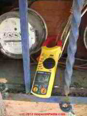
Our photo (left) illustrates using Sperry's Digisnap DSA-500 to measure the current draw of an individual electrical device - in this case, the charging block for a laptop computer.
Watch out: avoid death or blowing up your test equipment. When measuring amps without a current clamp, make sure power is off before connecting into the circuit.
Additional safety advice specially applicable to using VOMs, DMMs and ammeters, including both personal safety and advice to avoid damaging the equipment is found
at DMMs VOMs SAFE USE OF and
What's the Difference between Determining Service Ampacity and Measuring Amps at an Electrical Service, Circuit, Appliance or Device?
In this article we describe various methods for actually measuring the amps or electricity usage at a building, circuit, or device. But first, let's not confuse the determination of the ampacity of an electrical service at a building with amps measurement at a building, electrical circuit, or device.
What's the difference between determining the ampacity of the electrical service at a building and making actual amps measurements at an electrical service, circuit, or electrical device?
Making an amps measurement on a building circuit or at an appliance, motor, or air conditioner etc.
Measuring electrical amps is the measurement of current draw or amps or amount of electricity being consumed is an actual instantaneous measurement of actual electrical power use at the moment, not a measurement of the design capacity or capability of the electrical service at a building or in an electrical circuit.
The actual current draw or total amps being consumed on an individual electrical circuit in a residential building should (with minor technical exceptions) be a number below the ampacity of the circuit breaker or fuse protecting that circuit - typically 15Amps, 20Amps, or for some appliances a larger number, e.g. 30A or 40A at an electric water heater and at some central air conditioner/heat pump systems.
Of course if no electrical devices or appliances are turned "on" at an individual electrical circuit, the amps or current draw measured there should be zero.
Determining the total electrical service ampacity for a building
Ampacity ratings describe the safe capacity of an electrical system, circuit, or device, not the actual amount of electrical energy that that system, circuit, or device may happen to be carrying or using at a particular moment. For example, a #14 gauge copper electrical wire is typically rated to safely conduct 15 Amps (15A) of electrical current while a #12 copper wire is rated to safely conduct 20A of electrical current.
Determining the electrical service ampacity means answering the question "how much total electrical power or current can a building's electrical system safely use at one time?"
We discuss this procedure in detail beginning
Practically, the total capacity of an electrical system, measured in amps, sets the limit on how many electrical devices (lights, refrigerators, air conditioners) can be run simultaneously without overloading the system.
Overloading an electrical system or overloading an individual electrical circuit should trip a circuit breaker or blow a fuse. If those safety devices are subverted, not properly installed, are defective, or malfunction, the risk is that an overheated wire or connector or device ignites a building fire.
The service ampacity at an individual residential building typically will be somewhere between 60Amps (below current minimum standards for a home in the U.S. or Canada) and 200Amps.
We define Amps, Volts, and other electrical terms in more detail
What's the Difference between Measuring Amps and Actual Total Electricity Usage?
When we make an amps measurement at a building we are determining the current draw for all of the electrical devices that are in operation at that moment. We are seeing the rate of electricity usage.
Only by including the length of time that a building, circuit, or device is using electricity at a given rate (and voltage) can we know the total electricity used. That's the job of electrical meters. Typically we express electrical usage rates in watts, where Watts = Volts x Amps.
See DEFINITION of WATTS and
also DEFINITION of POWER FACTOR, REAL POWER
for examples of actual calculations of electrical energy usage that combines volts, amps, and other terms in order to accurately describe the electricity or energy used by a light bulb, an air conditioner, or other electrical circuits or devices.
Procedure for Measuring the Actual or Momentary Amps in Use (Current Draw) At A Building
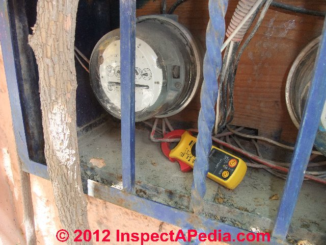
In our page top photo and in our photos here you can see Sperry's Digisnap DSA-500 snap-around digital multimeter in use measuring the amperage level on a 120V electrical circuit fed into a building from the electric meter.
The jaws of the DMM-ammeter are closed around one 120-V service entry wire in its routing between the electric meter's output lug and the electrical panel's main input connecting lug (not shown in this photo).
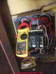
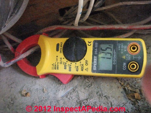
In the U.S. and Canada it would usually be necessary to open the electric meter enclosure to access these wires. You can see that at the moment of measurement, this 120V circuit was drawing only 1.35A. Inside we observed that the only operating devices on this circuit were some electric lights and computer equipment.
As our at left illustrates, we could have made this same measurement inside the electrical panel itself by clamping the DMM's transformer jaws around the service entry wire just above its connection to the main lug in the panel.
In a crowded electrical panel and depending on just which wires are available with least disturbance it may be tempting to try measuring amps at the main neutral wire.
For technical and accuracy reasons we do not use the neutral wire for this purpose.
Watch out: fatal electrical shock hazards are present.
Do not open an electrical meter enclosure nor electrical panel if you have not had proper safety training and/or if you do not have proper safety equipment.
Procedure for Measuring the Amps or Current Draw on an Individual Electrical Circuit
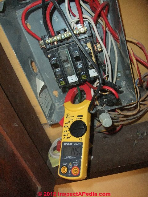
Our photo at above left illustrates measuring the current draw in amps of an individual electrical circuit in the building.
Taking care not to disturb the circuit breaker and moving other wires as little as possible (note that gray twist-on connector and electrical splice in this panel), we clamp the ammeter jaws around one 120-V wire below its connection to the circuit breaker.
Of course this measurement is meaningless if nothing is operating on the circuit being tested and has little meaning unless we know what devices that electrical circuit is powering. For example, measuring a dedicated electrical circuit for an air conditioner or refrigerator will produce varying results:
- Appliance off completely - zero amps
- Appliance fan only or light only operating - typically very low, possibly < 1A
- Appliance compressor motor in operation - highest amperage draw
Procedure for Measuring the Amps or Current Draw by an Individual Electrical Appliance, Device, Motor, etc.
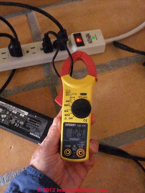
At left we are measuring the current draw in amps for the charging block of a laptop computer.
Notice that the electrical wire was split so that the clamp-on ammeter's jaws surround just one of the two electrical wires. The transformer jaws or "clamp" must surround just one of the two 120V wires supplying the electrical device.
Also notice that we did not disturb nor damage the electrical wire insulation itself - doing so is dangerous and risks equipment damage or dangerous electrical shock as we cite just above.
At the moment of our measurement this electrical device was drawing 0.29A at 120V.
For an accurate calculation of actual energy consumed that includes the effects of AC current and power factors,
see DEFINITION of POWER FACTOR, REAL POWER
For details about connecting probes and setting function and level switches on VOMs and DMMs
see DMM DIGITAL MULTIMETER HOW TO USE.
Reader Comments & Q&A
On 2021-09-22 by Eddie - electrical diagnostic procedure for well pump
[Ed. note: this reader's question and our complete discussion above was originally posted at WELL PUMP WIRING REPAIR FAQs]
I have a submersible well pump that fills a 5000 gal. storage tank. Pump motor is controlled by a pump motor control with protection device inside, and a Pumpmaster float switch.
My problem, that is now present from original installation, seems to be control of the power to the pump. When float switch activates pump motor, it fills normally for about 10 minutes and then clicks off and immediately back on, and keeps pumping as if nothing happened. A few minutes later it repeats.
After multiple episodes the pump appears to struggle but keeps running and just flowing 1/2 the amount of water for about 20 seconds and then resumes normal flow.
This series of actions continue until float switch opens (tank full). However the relay in the control box continues to click on and immediately off repeatedly with no activation of pump ( as pump switch is open). There is no shortage of water. No sediment/debris visible in bottom of tank (clean) to indicate clogging. Float switch is not bobbing in tank. Correct voltage is present and all connections checked and good.
Pump motor insulation and windings all test good. Motor control capacitor and relay test good. Swapped out motor control and float switch with same known good components - no change in problem. Any ideas? Thank you.
On 2021-09-22 by inspectapedia.com.moderator (mod) - pump protection device operation
@Eddie,
Just some vague guesses: consider how the pump protection device works. Usually it's monitoring current draw or Amps as an indicator that a pump may be running dry (and thus subject to damage). So we could have low voltage, or a failing sensor in the pump protection device itself, or even a constriction in the piping system (you've checked for this).
I am assuming your 5000g tank is not pressurized and that no pressure control switch and loss of air in the tank is causing trouble.
Start by identifying the exact pump protection advice installed: brand and model, then tell us that information; let's both read how that device works and what might cause it to short cycle.
On 2021-09-22 by Eddie
@inspectapedia.com.moderator, Sorry for slow response; I'm working many projects on large acreage. I have suspected the protection device and glad your thinking is along mine.
Here's the little troubleshooting I mustered up: first I removed the device and plugged pump control panel back in momentarily, turn on breaker and relay resumed clicking on and of just as when protection device is in.
I reinstalled the device and played with both it's "restart delay/calibration adjustment adjuster" and played with "sensitivity adjuster". No affect at all , except if I left it in reset position, then clicking intervals slowed way down.
The protection device is PumpSaver Plus by SymCom. Model 231-Insider-P. (1/3 - 1HP, 230 vac). There is no low water level. No constriction ( unless caused by low voltage or voltage drop somewhere slowing the pump momentarily and intermittently) that I can not find when looked for. Yes your assumption of 5000 gal tank is correct.
It is only a gravity supply to a Goulds booster pump on a separate circuit controlled by Square D pressure switch to supply pressure to bladder tank. And right now this is not an emergency situation as I visually monitor storage level and turn on breaker to fill tank when needed so relay does not sit there clicking . It is low use so I have only had to do this once a day, as I have another well system for all daily needs. Thank you .
On 2021-09-23 by inspectapedia.com.moderator (mod) - check both pump voltage and pump amps
@Eddie,
It probably would be useful to confirm the actual voltage being supplied and to check the current draw of the pump for any abnormal amperage level that would indicate a pump problem.
Watch out: if you're not familiar with electrical tests, you could be shocked or killed.
On 2021-09-23 by Eddie
@inspectapedia.com.moderator, Voltage at L1 /L2 is 230v. Which terminals at pump control box do I use for checking running amps, I assume it would be the run wire(s)? Using my VOM, please advise the correct method.
Also I'll be ordering new protection device like the module currently installed. As noted in my last comment I don't believe it is functioning correctly. And lastly (unless amp test shows problem) I may replace pump switch leads that run from tank to control box on chance somewhere in the conduit underground it has been compromised.
On 2021-09-23 by inspectapedia.com.moderator (mod) - how to measure amps or current draw at the pump
@Eddie,
See our discussion above on this page for AMPS MEASUREMENT METHODS
Watch out: fatal electrical shock hazards are present.
Do not open an electrical meter enclosure nor electrical panel if you have not had proper safety training and/or if you do not have proper safety equipment.
On 2021-09-23 by Eddie
@inspectapedia.com.moderator, I guess I should have phrased it differently regarding amp measurement . I know how to safely test amp with multimeter (in series). What I wanted to know was if it mattered where since pump control panel is closed to run.
I guess I do it at sub panel next to pump control and connect in series at float switch wire that connects breaker to pump control. May I ask are you the same person who I started all this with, or do the moderators change?
On 2021-09-24 by inspectapedia.com.moderator (mod) - measuring pump amps
@Eddie,
I'm same mod, in this case, but a few days older.
We do have more than one editor. And moderators may discuss and compare notes in forming an answer.
Typically you would use a clamp-on ammeter on the individual leads to the pump.
On 2021-09-25 by Eddie
@inspectapedia.com.moderator, Thank you. Yes I agree clamp-on would be best and until this point have not had need for that specialty meter, but should get one.
One more bit of info though: this well problem is from well pump originally installed by original owner, who is long gone and I have now become care taker of it. My other well is my install and I have kept record of everything. So this other well pump with problem is unknown make, model, depth, and I can only assume 1/2 hp as indicated by control box (who knows if that is even correct one for pump).
I see so much of install that, yes, it has worked, but not the way I would have installed it. So not knowing it's particulars, amp reading may or may not help unless it is so far off chart for any average 1/2 hp pump.
While waiting for new sensitivity device to arrive I listened to pump operation with ear pressed to up pipe, and occasionally and intermittently a growl can be heard that sounds like maybe a the thrust bearing is failing and causing impeller to shift enough to rub but not bind pump enough to trip off.
So it really still appears to be a intermittent momentary stop in supply power to pump. One other thing, this could probably be original pump, putting it at 25 yrs approx age. If so, replacement would be warranted.
I just wanted to be sure problem is not above ground. And thank you for your individualized assistance. Easier than someone else filling in and maybe not going back over everything I've provided to this point.
On 2021-09-25 by inspectapedia.com.moderator (mod) - amps or current draw test for well pump
@Eddie,
That's why the amps test is useful, to get an idea of the condition of the motor before pulling a pump.
It's also possible that the noise you're hearing is from a failing impeller assembly.
On 2021-09-27 by Eddie - finally ready to test my pump's current draw
@inspectapedia.com.moderator, Sorry for late follow up, Been busier than usual. Finally picked up "amp clamp". When well pump running as normal (full flow out of fill pipe to tank) I read 6.5 amps. When flow reduces to 1/2 normal flow (noticeable "growl" with ear to pump up pipe) amps drop 1 full amp to read 5.5 amps.
That particular situation happens NOT very frequently and intermittently (without any pattern). Flow of water never stops completely.
When tank is full and float switch breaks power, everything is normal / quiet, except for pump control relay clicking (I assume on and off, but no momentary show of amps comes up. Still waiting on new sensitivity device to see if that is affecting control.
On 2021-09-27 by inspectapedia.com.moderator - electrical tests of submersible well pump before pulling it out of the well
@Eddie,
Thanks keep us posted; also double check to see if the current variation occurs at the same time as the growling noise;sounds like it's time to pull the pump;
In doing-so, also check the well piping and wiring as they rise out of the well casing - for signs of abrasion or wear that might tell us that the pump was torquing and twisting the pipes and wires.
On 2021-05-26 by Bill - I wanted to put my multimeter on the two main lines coming into my breaker panel to measure amps
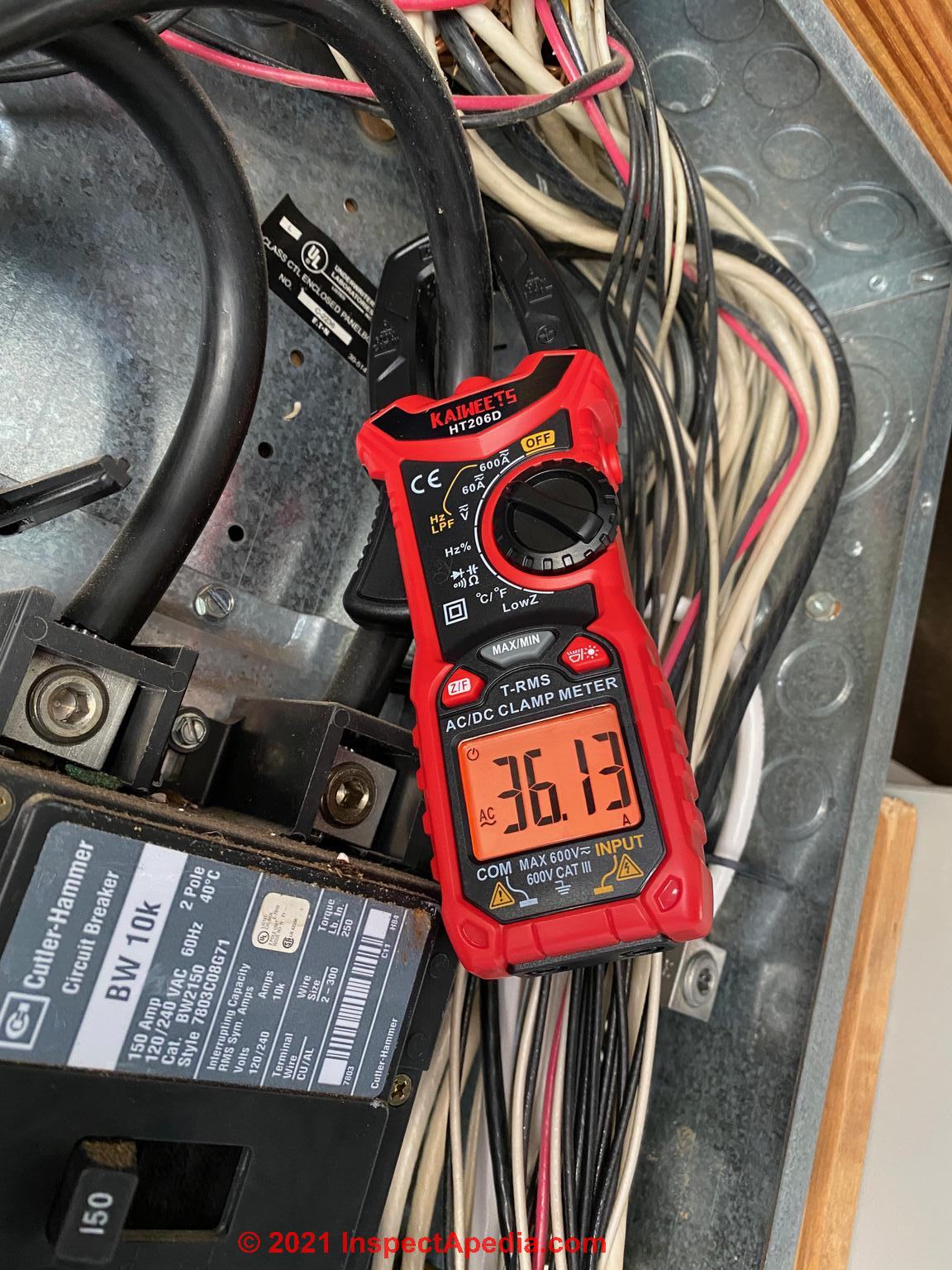
Question. I wanted to put my multimeter on the two main lines coming into my breaker panel to measure amps on each one and then calc to Watts to see what size generator i needed to run my AC units, etc. The left wire read 34.62 amps and the right read 36.13 amps.
[See Bill's photo, above - Ed.]
I assume that with both my 4 ton and 5 ton units AC units running, I am consuming 70.75 amps while both are running. If i am calculating right, is that 8,490 watts?
Thus a 7500 continuous/9375 peak would not be quite enough to handle both. Just wanted to confirm my conversion from amps to watts was correct and i am looking at this correctly. Thanks, Bill
On 2021-05-26 by (mod) - procedure for measuring A/C unit amps in planning to buy a backup generator
@Bill,
Watch out: You're measuring amps or current using a clamp-on ammeter in your main panel and looking at the entry means coming in but is it correct that there's absolutely nothing else running in your building except your air conditioner when you made that measurement?
When an electrician wants to measure the current draw of a specific device or circuit she'd use her clamp-on ammeter on the wires of that circuit, not the panel's entry mains.
DEFINITIONS AMPS VOLTS WATTS
Is a good place to make sure we've got these simple definitions and formulas right.And for other readers,
Watts = Volts x Amps
Excuse me but I also must warn
Watch out: anyone who was not trained in familiar with safe electrical practices should stay out of the electrical panel because it's very easy to be shocked or killed.Look at the data tag on your AC unit at both the LRA and RLA - the "lock rotor amps" is the highest draw or surge that might occur during start-up - your generator needs to be able to handle that or you might be trying to start the unit with too-low current.
Look at the data specs on your generator to see what is its surge capacity.
A seat-of-the-pants way to do this is to look at the circuit breakers that supply your A/C system. Typically those will be a slow-trip breaker that tolerates a brief overcurrent; so if your A/C unit is powered by a 40A 240VAC circuit it might actually draw 46 A during startup but run fine on a 40A circuit.
Let me know what you think.
On 2020-05-3 by Bob measuring amps for a 230V motor with a Fluke amp-probe,
When measuring amps for a 230V motor with a Fluke amp-probe, do you measure each line individually then add together for total amps?
On 2020-05-31 by (mod) -
Thank you for a great question Bob.
The answer is yes;
with a typical amp measuring device, we clamp the meter around an individual line or wire measuring one at a time.
That's particularly useful on a 220, 230, 240 volt circuit as it's possible that the load and therefore the current draw or amps will be different on each of the two lines.
An interesting example is an electric clothes dryer. Even though the dryer is wired to 240v, separate individual heaters in the dryer may each run on 120 volts, offering different dryer temperatures depending on whether one or both heaters has been activated. We see a similar usage or splitting of the 240 into to 120 volt circuits on electric stove top burners.
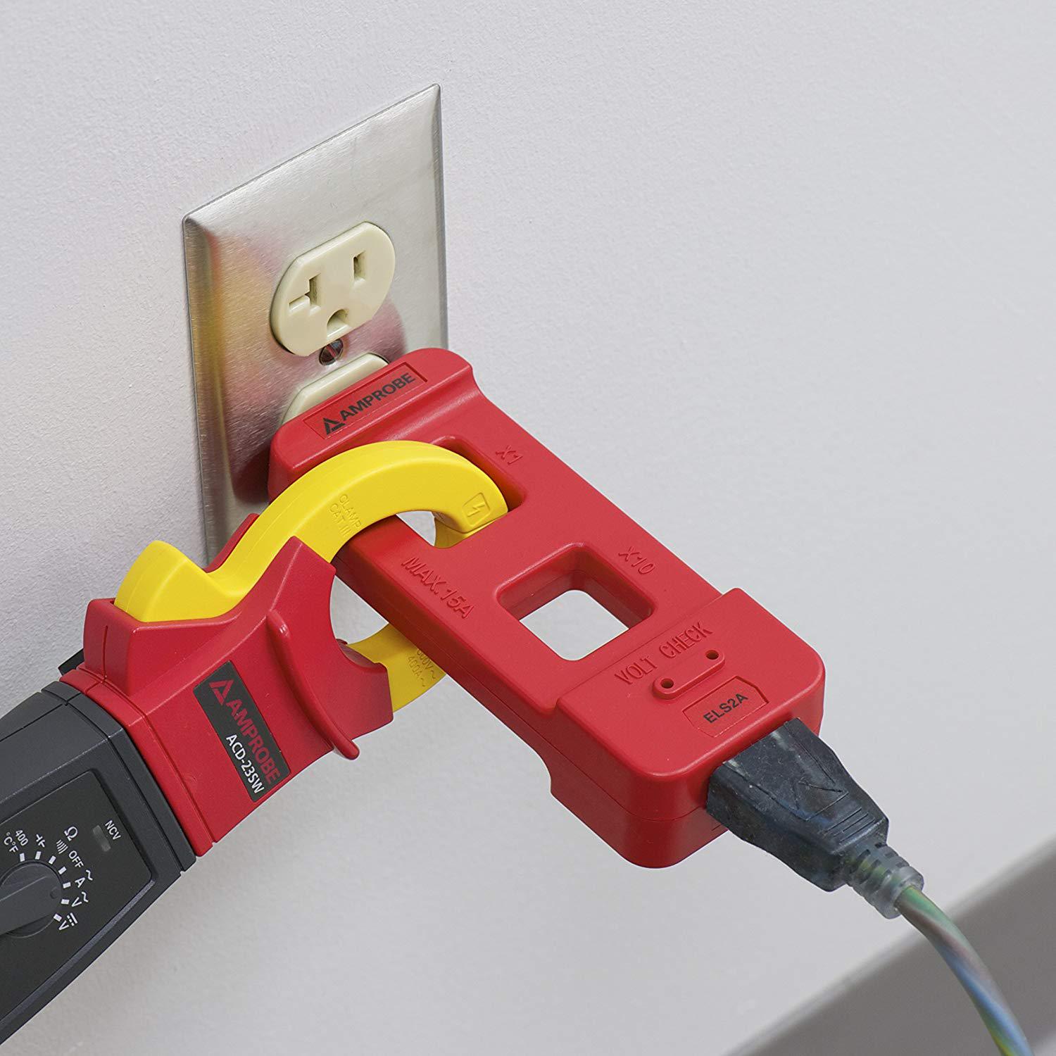
On 2020-01-26 by Not An Electrician - splitting wires to measure amps? Electrician comments.
Jeez, in the US we usually don't split any electrical wiring that we want to continue using .
also there's an amps limit to what you're wise to measure with your $30 clamp meter, or even your $300 one. I wouldn't measure a US home's service wire myself, for example.
Not in the box, and not at the mast. Some things are best left to electricians.
That said, it should be fine to measure the hot wire of any branch circuit you'd encounter in a typical home electrical box.
On 2020-01-26 - by (mod) -
Nota
I like the Amprobe current measurement set-up in your photo as safer than fooling around in an electrical meter or panel box.
To be clear, we warn readers:
Watch out: do not attempt to open an electrical panel, meter base, nor to do electrical wiring if you're not trained and qualified to do so. You could be shocked or killed or set the building on fire.
That said, the Amprobe demonstration in your message can work on an electrical receptacle circuit but for measuring the current draw of other circuits, lighting, heating, air conditioning, or equipment, pumps, compressors, more-direct means will be needed - those measurements are regularly made by people trained to do so, such as service technicians and some inspectors and diagnosticians. They are not homeowner tasks.
Thanks for the comment.
On 2017-07-20
by Matt - determine the Amp Service to a commercial property
How do I determine the Amp Service to a commercial property we are renting for business use
On 2017-05-02 by Chris
I am currently renting a space where the HVAC unit for my address is located in an adjacent space. Therefore, it is also on the meter in that space. Is there a way to measure what electric is being used by my HVAC unit only?
On 2017-07-20 - by (mod) -
Matt, and Chris:
if you are asking about determining the ampacity presently installed, it will be determined by the smallest Link in the chain of electrical components from the overhead service or Underground Service entry cable from your utility company.That is to say, the size of the service entrance cable, the meter capacity, the ampacity of the main circuit breaker in your electrical panel or main disconnect. If you are asking how to determine the ampacity that you need, that's determined by what equipment you are going to run.
That's not something I can guess from your question.
...
Continue reading at VOLTS MEASUREMENT METHODS for measuring volts or voltage levels or select a topic from the closely-related articles below, or see the complete ARTICLE INDEX.
Or see these
Recommended Articles
- AMPS VOLTS DETERMINATION - home
- AMPS, LIMITING FACTORS
- AMPS & SEC SIZES
- AMPS & VOLTS, DETERMINE VISUALLY
- AMPS MEASUREMENT AUTOMOTIVE DC
- AMPS MEASUREMENT METHODS - you are on this page
- AMPACITY, MAIN DISCONNECT
- DEFINITIONS AMPS VOLTS WATTS
- ELECTRIC METERS & METER BASES
- ELECTRIC MOTOR HORSEPOWER & CIRCUIT WIRE SIZE
- ELECTRICAL PANEL AMPACITY
- VOLTAGE at the SEC
- UNDERGROUND SERVICE LATERALS
- AMPS MEASUREMENT AUTOMOTIVE DC
- AMPS MEASUREMENT METHODS
- ANALOG VOMs & MULTIMETERS
- DMM DIGITAL MULTIMETER HOW TO USE
- DMMs VOMs SAFE USE OF
- DO IT YOURSELF ELECTRICAL WORK
- MINI AMMETER for measuring thermostat heat anticipator
- SAFETY for ELECTRICAL INSPECTORS.
- VOLTS / AMPS MEASUREMENT EQUIP
- VOLTS MEASUREMENT METHODS
Suggested citation for this web page
AMPS MEASUREMENT METHODS at InspectApedia.com - online encyclopedia of building & environmental inspection, testing, diagnosis, repair, & problem prevention advice.
Or see this
INDEX to RELATED ARTICLES: ARTICLE INDEX to ELECTRICAL INSPECTION & TESTING
Or use the SEARCH BOX found below to Ask a Question or Search InspectApedia
Ask a Question or Search InspectApedia
Try the search box just below, or if you prefer, post a question or comment in the Comments box below and we will respond promptly.
Search the InspectApedia website
Note: appearance of your Comment below may be delayed: if your comment contains an image, photograph, web link, or text that looks to the software as if it might be a web link, your posting will appear after it has been approved by a moderator. Apologies for the delay.
Only one image can be added per comment but you can post as many comments, and therefore images, as you like.
You will not receive a notification when a response to your question has been posted.
Please bookmark this page to make it easy for you to check back for our response.
Our Comment Box is provided by Countable Web Productions countable.ca
Citations & References
In addition to any citations in the article above, a full list is available on request.
- Daniel Friedman - Publisher & Editor of InspectAPedia.com®
- N. Srinivasan, MSEE, is a senior member of IEEE with 30 years experience in the electrical industry. Mr. Srinivasan is in Vienna VA.
- Louis P. Babin generously contributed technical editing about the effects of doubling ampacity in an electrical circuit (September 2007)
- ASHI Technical Journal, Vol. 2. No. 1, January 1992, "Determining Service Ampacity," Dan Friedman and Alan Carson, and the
- ASHI Technical Journal, Vol. 3. No. 1, Spring, 1993, "Determining Service Ampacity - Another Consideration," Robert L. Klewitz, P.E., with subsequent updates and additions to the original text ongoing to 2/19/2006. Reprints of the originals and reprints of the Journal are available from ASHI, the American Society of Home Inspectors www.ashi.com.
- [4] Digisnap DSA-500 snap-around digital multimeter, A.W. Sperry Instruments Inc., 2150 Joshua's Path, Suite 202, Hauppage NY 11788, Tel: 800-645-5398, Email: cat@awsperry.com, Website: www.awsperry.com
- [5] Fluke Corporation, 6920 Seaway Blvd, Everett, WA 98203, USA, PO Box 9090 Everett, Washington 98206, Tel: +1(425) 347-6100, Technical support: 1(800) 44-FLUKE (1(800) 443-5853), Website: www.fluke.com,
Fluke Europe B.V, PO Box 1186 Eindhoven, The Netherlands, Tel: +31 (0)40 2 675 200 +31 (0)40 2 675 222, Website: www.fluke.eu - Digital 287/289 Digital Multimeter, Users Manual, retrieved 9/5/21, original source: http://assets.fluke.com/manuals/287_289_umeng0200.pdf, [copy on file as Fluke_287_289_umeng0200.pdf]
- [6] Simpson Electric, P.O. Box 99, 520 Simpson Avenue, Lac du Flambeau, WI 54538-0099 Tel: 715-588-3311, customer service: 715-588-3947, Email: support@simpsonelectric.com, Website: www.simpsonelectric.com/
- Simpson 260® Series 6XLM Volt-Ohm-Milliammeter Instruction Manual, retrieved 9/5/2012, original source: http://www.simpsonelectric.com/uploads/File/datasheets/260-6xlm.pdf, [copy on file as Simpson_260-6xlm.pdf]
- [7] tif 300cc Tic Tracer voltage detector, Tif Instruments Inc., 9101 NW 7th Avenue, Miami, Florida 33150
- [8] Greenlee® GT-16 adjustable voltage detector, Greenlee Textron Inc., Website: greenlee.com, Tel: 800-435-0786 , Email: echsupport@greenlee.textron.com,
- "Electrical System Inspection Basics," Richard C. Wolcott, ASHI 8th Annual Education Conference, Boston 1985.
- "Simplified Electrical Wiring," Sears, Roebuck and Co., 15705 (F5428) Rev. 4-77 1977 [Lots of sketches of older-type service panels.]
- "How to plan and install electric wiring for homes, farms, garages, shops," Montgomery Ward Co., 83-850.
- "Simplified Electrical Wiring," Sears, Roebuck and Co., 15705 (F5428) Rev. 4-77 1977 [Lots of sketches of older-type service panels.]
- "Home Wiring Inspection," Roswell W. Ard, Rodale's New Shelter, July/August, 1985 p. 35-40.
- "Evaluating Wiring in Older Minnesota Homes," Agricultural Extension Service, University of Minnesota, St. Paul, Minnesota 55108.
- In addition to citations & references found in this article, see the research citations given at the end of the related articles found at our suggested
CONTINUE READING or RECOMMENDED ARTICLES.
- Carson, Dunlop & Associates Ltd., 120 Carlton Street Suite 407, Toronto ON M5A 4K2. Tel: (416) 964-9415 1-800-268-7070 Email: info@carsondunlop.com. Alan Carson is a past president of ASHI, the American Society of Home Inspectors.
Thanks to Alan Carson and Bob Dunlop, for permission for InspectAPedia to use text excerpts from The HOME REFERENCE BOOK - the Encyclopedia of Homes and to use illustrations from The ILLUSTRATED HOME .
Carson Dunlop Associates provides extensive home inspection education and report writing material. In gratitude we provide links to tsome Carson Dunlop Associates products and services.
 | HOME | ABOUT | ASK a QUESTION | CONTACT | CONTENT USE POLICY | DESCRIPTION | POLICIES | PRIVACY | |
| © 2024 - 1985 Publisher InspectApedia.com - Daniel Friedman | |||||||||