
InspectAPedia® FREE Encyclopedia of Building & Environmental Construction, Diagnosis, Maintenance & Repair |
Question? Just ask us! InspectAPedia
|
 Guide to Refrigeration Gas Test Gauge Use
- POST a QUESTION or COMMENT about how to hook up and use an air conditioner, heat pump, or other refrigeration equipment refrigerant gas pressure test gauge
Air conditioner & heat pump refrigerant test gauges: this article describes the connections, use, and reading of a refrigerant gas pressure test gauge set.
We describe the procedure for using test gauges when adding or replacing refrigerant: charging an air conditioner, heat pump, refrigerator with refrigerant gas.
We explain how a refrigeration gauge set should be connected to HVAC equipment to avoid contamination damage and we review the refrigeration system evacuation and cleaning procedure.
InspectAPedia tolerates no conflicts of interest. We have no relationship with advertisers, products, or services discussed at this website.
- Daniel Friedman, Publisher/Editor/Author - See WHO ARE WE?
Details on Proper Use of the Refrigeration Charging / Testing Gauge
To keep moisture & dirt out of an air conditioner, heat pump, refrigerator, freezer, etc., in addition to finding and fixing leaks, we need to know how to properly use a refrigerant gauge set with charging lines, and how to use cap off plugs on the charging fittings.
To be clear, when connecting an HVAC refrigeration gauge set to test fittings on an air conditioner or heat pump we must:
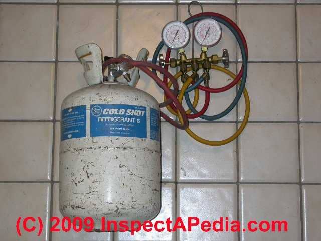
- Connect the gauge set center supply tube to a canister of the proper refrigerant gas matching the refrigerant in the system being tested
- Leave some positive pressure of refrigerant gases in each of the two gauge test connection hoses
- the high pressure side and the low pressure side,
so that when the gauge hose fitting is connected to the service port on the HVAC equipment no outside air or moisture are pushed into the system piping.
Refrigeration Servicing Gauge Set Installation & Use
Reading the Gauges on a Refrigeration Gauge Set
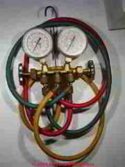
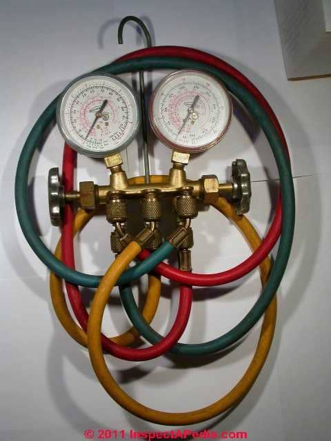
We use (and illustrate) a traditional Imperial System Analyzer gauge set that provides three charging lines (refrigerant canister, high side, low side). This is a diaphragm type gauge but other methods of measuring and charging systems are available.
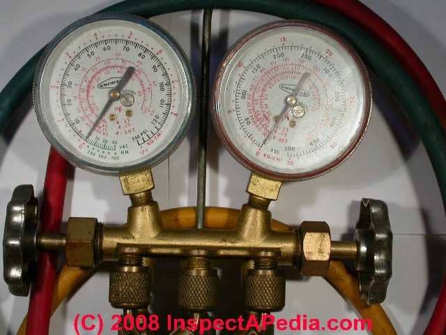
How to Read the Low Pressure Side Refrigerant Gauge
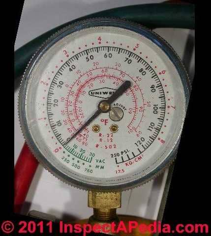 The compound gauge at left is used on the low pressure side of the system and shows pressure readings in black, from 0 to 300 psi gauge pressure. [Click any image to see an enlarged, detailed version.]
Temperature corresponding to pressure is shown in red on this gauge for R12 and R22, or for newer refrigerants on newer gauges.
Vacuum is also shown on this gauge on a scale from 0-30 in. Hg. in green..
Reminder: as we discuss
at REFRIGERANT PRESSURE READINGS & CHARTS
if you use pressure test gauges to measure the refrigerant pressure in the static or equalized air conditioning or heat pump system, the gauges only tell you the refrigerant pressure, not the quantity of refrigerant that is present in the system.
For example at 70F ambient temperature and with R12 refrigerant, the static system pressure would be at 70 psi as long as there is enough refrigerant in the system to have at least some in liquid state.
Reading the High Pressure Side Refrigerant / HVAC Test Gauge
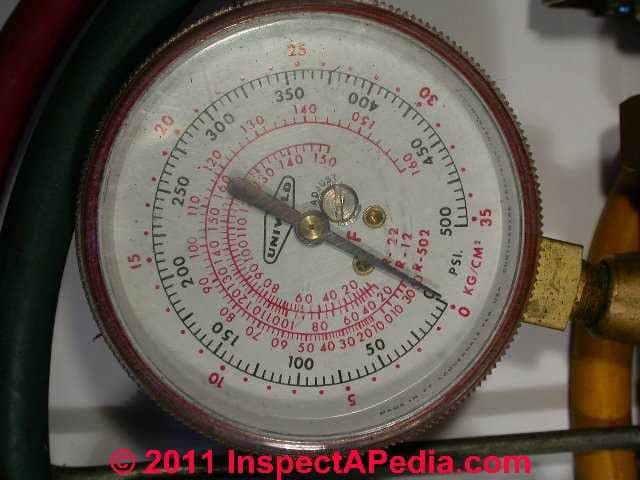
The compound gauge on the right of this gauge set is used on the high pressure side of the refrigeration system and shows refrigerant pressures, typically from 0 - 500 psi on the black scale or 0 - 35 KG/CM3On the outermost red scale.
In the center of the refrigerant gauge the red scales give temperature readings for three older refrigerants (this is an old gauge): R502, R12, and R22.
Attaching the Refrigeration Gauge Set to the Air Conditioner, Heat Pump, or other refrigeration equipment
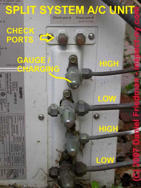
Find the service ports
Central air conditioning systems, heat pumps, and split systems typically have service ports installed specifically for the attachment of test gauges for system inspection, evacuation, and charging.
Residential refrigerators, freezers, and window or portable air conditioners typically will not have these service ports.
To service one of those latter devices you'll need to cut the refrigerant line and install (solder in place) a tee and a service port.
Our photo (left) shows four covered service ports on this split system compressor/condenser unit. That's because this unit supports two indoor wall-mounted cooling units.
If its not obvious to you that the larger diameter line is the low pressure or suction side and the smaller diameter refrigerant line is the high pressure side, then really you should not be messing with this equipment before taking a refresher class in HVAC servicing and repair.
Using Temporary Access Valves for HVAC or Refrigeration Testing & Diagnosis
Tapaline® and other piercing valves are available in various sizes to allow the HVAC technician to tap into the refrigerant lines on a system in order to perform diagnosis where there are not already service valves installed. Smaller bullet-type valves are installed using an allen wrench.
Use these valves as a temporary service tool, preferably attached on the process tube.
See COMPRESSOR / CONDENSER TYPES if you don't know what a process tube is.
Watch out: do not leave these temporary test valves on the refrigerant piping - you're asking for a future leak. These valves are suitable to aid diagnosis of a refrigeration system by avoiding disturbing the troubled state of the system (as you'd do if you had to cut lines and solder in service valves just to do a test).
After using a temporary tap-in valve on the process tube at a compressor unit, you should solder off the line puncture and add a permanent service valve fitting - the type that uses a schrader valve and cap - also referred to as an access valve or line valve.
Connect the Test Gauges to the Air Conditioner, Heat Pump, etc
 In the shop we connect both high and low pressure gauges to the equipment being tested. In the field technicians often use only the low pressure side of the HVAC test gauge set, since high side problems also show up on the low side.
On test gauge sets such as ours shown here, the service lines always open or close a connection between the HVAC equipment refrigeration test ports and the gauges.
The end-valves (silver handles) on either side of the gauge set then open or close a further connection between that valve and either high or low side connection and the yellow hose that will in turn connect to a refrigerant source.
You'll notice in our photo that both ends of the refrigerant hoses are attached to the gauge set.
On the front of this gauge (and more easily seen in the photograph) are three blind connector plugs to which we connect the hoses when the gauge is not in use - this step is to help keep the gauge hoses clean of debris.
In the photo at left, the "live" hose connection ports are somewhat hidden behind the gang of hoses and the "blind" connectors used to keep the hoses and their end connectors clean when not in use.
The gauge set has stop valve handles that you see on either side of the gauge. These controls open or close the high or low side service lines once they have been properly connected to the high or low side service port.
As we've mentioned before, we would not normally connect our gauge set to the service ports without first attaching a can of the proper refrigerant to the gauge set service port and then using that refrigerant to purge any air that may be in the refrigerant hoses.
That's to avoid blowing air and contaminants into the HVAC system.
[Click to enlarge any photo to see more detail]
On our air conditioner or heat pump test gauges we use a
- A blue flexible hose on the low-side gauge. In the photo above the blue hose is connected to the left-hand low pressure gauge port, while its free end is connected to a right-hand blind port.
When in use the free end of the low pressure gauge is removed from its "blind port" and is then connected to the low side of the system at that service port. - A red hose on the high side gauge. In the photo the red hose is connected to the right-hand high pressure gauge and its free end
- the end that will connect to the HVAC equipment test gauge port - is connected to a left-hand blind port to keep the fitting clean when not in use.
The high pressure gauge (red hose) will be connected to the high side of the system at that service port. - A yellow hose on the center gauge service port just to help avoid any confusion in the field.
The free end of the yellow hose is also connected to a center blind port to keep out debris.
The center service port on the gauge set will connected to a refrigerant canister, charging device, or to an evacuator pump, depending on what the HVAC technician needs to do.
Depending on which valves you open or close, this gauge set permits both checking pressure and/or charging the refrigerant system on either the high side or the low side.
Watch out: Even all three hoses of your gauge set is connected to high side, refrigeration canister or charging cylinder, and low side, never open both high side and low side gauge connection valves at the same time.
Exposing the low side and gauge to high pressure could certainly blow the gauge, damage the HVACR system, and cause serious injury as well. - Thanks to reader NJSnowman for suggesting this clarification, via comments. 2016/08/16
Refrigerant Test Gauge Hose Hookup Details
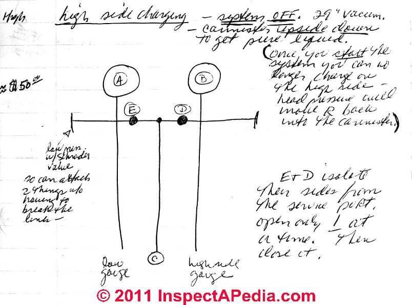 In our sketch at left
- (A) is the low side pressure gauge,
- (B) the high side pressure gauge,
- (C) is the service line at the gauge center, connected to a refrigerant gas source or perhaps to an evacuator pump.
- (D) is the location of the high side gauge control valve and
- (E) is the functioning location of the low side control valve.
Watch out: not all HVAC test gauge sets may have their high pressure and low pressure gauges in the same left and right positions.
What is critical is that the low pressure gauge is connected to the low pressure port (by convention using a blue hose) and the high pressure gauge is connected to the high pressure port (by convention using a red hose).
Watch out: Valves (D) and (E) are used to isolate their sides from the service port.
Open only one control valve at a time, then close it before opening the other.
- Attach the refrigerant canister to the gauge set
- Loosely attach the low side gauge (A) line to the low side service port. Assure that the service valve is turned all the way OUT
- Open the refrigerant canister (C) and by opening the gauge valve (E - low side) purge the lines (do not use the system's refrigerant to purge the gauge lines)
- Tighten the service line to the service port
- Turn off the refrigerant gas canister supply
- Turn the equipment service valve in slightly and run the system. The gauge(s) will indicate what the system is doing.
Watch out: as we warn at many places in this article series, do not send liquid refrigerant into the low side of a refrigeration system.
Liquid refrigerant will enter the bottom of the compressor motor and can damage the compressor, or even if the compressor tolerates and passes the refrigerant through its pumping system, the refrigerant can carry away the lubricating oil from the compressor, and/or cause an air trap in the system.
Watch out: Never open both high side and low side valves on the gauge set at the same time.
Exposing the low side and gauge to high pressure could certainly blow the gauge, damage the HVACR system, and cause serious injury as well. - Thanks to reader NJSnowman for suggesting this clarification, via comments. 2016/08/16
We use the same procedure for attaching the gauges to the high side of the system.
Restating a bit:
For the gauge set shown above, turn the valves all the way out to attach the gauges, since service ports are stopped OFF.
- Turn the gauge control valve all the way in (closed) to stop off the line to the evaporator/condenser (depending on which valve you are using).
- Attach the gauge hose test line loosely to the test port;
- Feed a small amount of refrigerant through the gauge test line and the charging line to purge any air. [NOTE that newer test equipment may provide other solutions for this step to avoid releasing any refrigerant to the atmosphere.]
- Then tighten the connection of the test hose to the equipment service port.
To Remove the Service Test Gauges on Refrigeration Equipment
Back-seat (all the way out) the equipment service valve to close off the service port, then remove the gauge and cap both the service port and the test gauge hose ends.
What is the Process Port on an HVAC Compressor Motor & How is it Used?
Question: OK to use the process port or charging port on the compressor itself to charge the system?
2017/04/06 John said:
I am charging a Commercial kitchen fridge with the compressor and condenser located externally from the fridge itself.
The charging port on the service valve is leaking, there is a charging port on the compressor itself, can I use this to charge the system?
Reply: Yes
Yes, if you're charging with gas not liquid and you're on the suction side. But I worry that the leaky port is going to continue to leak - I'm not an expert but in my experiences the valve cap doesn't make a reliable long term seal.
John said:
Thanks, I check somewhere else and it tells me that the port I was talking about is a process port. There is the suction and discharge line, but this particular one says it's a process port. What worries me is the uncertainty of this process port. if it is on the low or high side of the compressor.
(Mod) said:
John,
Doing a little research about process ports I read that it's an "alternative suction line" - and on smaller HVAC compressor motors both ports are open to the same compressor chamber - so either could be used for charging.
In some HVAC texts the process port or tube is used to evacuate the system and would still be in common with the compressor suction side interior.
I have certainly read that HVAC techs charge (gas only ie low side) through a process port and even prefer that.
On some higher-efficiency or larger compressors that's not so clear as I note below though I think the principal difference is the port diamater and its intended use. On some larger compressors the process tube may be a smaller-diameter tube used for an auxiliary function such as an ice maker - still charging through that port could be OK.
A definitive answer would come from the manufacturer of the specific HVAC compressor motor.
The Tecumseh company warns:
Important! The AE2 is a high efficiency compressor and uses directed suction intake. It is necessary (with the exception of ice cube machine applications) to use the designated suction tube. For ice cube machines: Tecumseh recommends to use the process (alternate suction tube) as the suction tube.
And this PDF from Manitowoc
Here is another example of using the process port on a compressor motor, from Embraaco
How to remove a used compressor
We recommend that the used refrigerant fluid is collected for later recycling or incineration, according to the following procedure: First, install a perforating valve in the compressor process tube.
Connect the perforating valve to the recovery equipment that is then connected to the receiving cylinder. Now just connect the recovery equipment. Open the receiving cylinder valve and then the perforating valve.
It is very important to keep the recovery equipment operating as long as it is necessary to collect all refrigerant. The duration of this process will depend on the equipment used and refrigeration system. -
- COMPRESSOR APPLICATION MANUAL [PDF], Embraco, 2800 Vista Ridge Drive NE
Suwanee, GA 30024-3510
USA +1 678 804-1337,
Mexico, Torre Alestra, Piso 3 - Office 373 Av. Lázaro Cárdenas 2321 Pte. P.O. BOX 66260 - San Pedro Garza García Nuevo León - México Phone: +52 81 1001-7102,
Slovakia: Odorinska Cesta, 2 - 052-01 Spisská Nová Ves - Slovakia Phone: +42 153 417-2291 +42 153 417-2293,
Italy: Via Buttigliera 6 10020 - Riva Presso Chieri (Torino) -Italy, PO Box 151 - 10023 Chieri (TO), Ph : +39 011 943-7111,
Brazil: Rui Barbosa, 1020 - 89219-901 - Joinville - SC - Brazil Ph : +55 47 3441-2121 - retrieved 2017/04/07, original source: www.embraco.com/DesktopModules/DownloadsAdmin/Arquivos/g6fvojOMAG.pdf EMBRACO Compressor ApplicationManual - COMPRESSOR REPLACEMENT MANUAL [PDF], Manitowoc, Manitowoc Ice 2110 South 26th Street, P.O. Box 1720, Manitowoc, WI 54221-1720 USA 000013291 Telephone 920-682-0161, Fax - Sales: 920-683-7589, Service/Parts: 920-683-7585, Other: 920-683-7879 Web Site - www.manitowocice.com - retrieved 2017/04/07, original source: www.manitowocice.com/asset/?id=dqxfr
- TECUMSEH COMPRESSOR MOTOR DETAILS [PDF], Tecumseh Products Company, 5683 Hines Drive Ann Arbor, Michigan 48108, USA, Ph: 734.585.9500 - retrieved 2017/04/07, original source: www.tecumseh.com/~/media/north-america/files/installation-instructions/ae2-install-instructions-final-hires-032213.pdf
Continue reading at REFRIGERANT PRESSURE READINGS & CHARTS
or at OVER CHARGED of REFRIGERANT, EFFECTS or select a topic from the closely-related articles below, or see the complete ARTICLE INDEX.
How to Make Air Conditioner Pressure Gauge Readings
 In our illustration of air conditioner service equipment pressure test gauges at page top and at left, you notice that there are two gauges and two sets of connectors and control valves. "
Gauge pressure" can read either the pressure inside the condenser unit (the "high side" of the system) or the pressure inside the evaporator (cooling coil) or "low side" of the system.
The gauge set accepts three connecting hoses:
- Low pressure side (blue hose on my gauges)
- High pressure side (red hose)
- Refrigerant gas source (center fitting)
Note that gauge pressure is an absolute pressure reading before any correction for ambient temperatures around the unit. When comparing measured or gauge pressure with recommended refrigerant pressures it is necessary to correct gauge pressure for ambient temperature variations. A/C equipment, gauges, refrigerant charging manuals etc. include pressure charts to aid in this correction.
Low-side pressure calculation example
Using now-obsolete R-12 refrigerant gas as an example, looking at the low-side refrigerant pressure (the low side is the side at which the refrigerant liquid has boiled into a gaseous state), we can calculate the temperature at which the refrigerant should boil for given ambient conditions:
(38-45 degF example) - (18 degF temperature difference between inside the condenser and ambient) = 20 degF = the temperature at which the refrigerant must boil, i.e. the state change from liquid to vapor. Looking at 20 degF. in the table for R12 state changes shows us that we should see 21 pounds of pressure.
High-side pressure calculation example
At 80 to 100 psi pressure on the high side, if ambient temperature is 72 degF, heat will be transferred successfully to outdoor air at temperatures of 84 degF to 117 degF at the condenser coil.
Refrigerant Manifolds, Gauges, Test Tool Sources, Connections, Where to buy
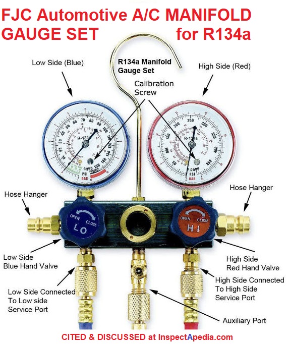
Illustrated here: the FJC A/C Products Co. Automotive Air Conditioning Manifold Gauge Set for R134a refrigerant systems.
[Click to enlarge any image]
Watch out: among some manufacturers, particularly of traditional dial-gauge type manifold sets for refrigeration system use at homes or at car or truck A/C systems, you will need a gauge whose pressure response and gauge indicator dial matches the specific type of refrigerant.
Newer vehicles will use an R134a Manifold gauge set while older vehicles will require use of an R12 Manifold Gauge set.
Some gauge sets or manifolds like mine shown at page top have scales that permit pressure readings of more than one type of refrigerant gas, of which the most-common may be R12 and R134a. You'll see dual refrigerant gauge manifolds included in the list of sources we give below.
At least some digital refrigerant manifold or gauge sets can accommodate more than one type of refrigerant gas. Below we include as an example the Testo 550 / 557 manifold digital gauge device.
- FJC A/C Products,Tools, Equipment TUTORIAL for USING MANIFOLD GAUGES [PDF] FJC Co., 101 Commercial Dr,Mooresville, NC 28115
USA, Customer Service: Admin@fjcinc.com
To Place an Order: Orders@fjcinc.com
Telephone: 704-664-3587 retrieved 2021/02/26 original source: https://fjcinc.com/a-tutorial-guide-to-manifold-gauges/
FJC, Automotive A/C MANIFOLD GAUGE SET INSTRUCTIONS [PDF] Op. Cit. illustrated above.
Below: a 4-valve gauge set or manifold provides additional connection ports as illustrated and discussed in JB Industries' instructions cited below.
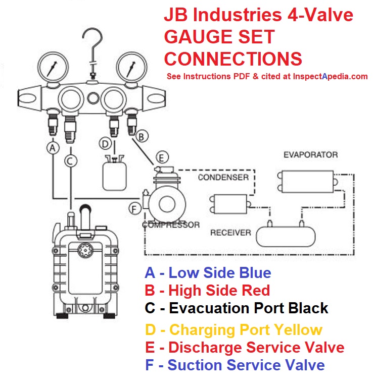
- JB Zepplin 4-VALVE MANIFOLD INSTRUCTIONS [PDF] JB Industries PO Box 1180 Aurora, IL 60507-1180 USA Tel, 800.323.0811 Customer Service: customerservice@jbind.com, Website: jbind.com - illustrated 4-valve manifold connections are given above, as an excerpt from these instructions, retrieved 2021/02/26 original source: http://www.jbind.com/pdf/4%20valve%20manifold%20instructions.pdf
- Mastercool, R134a MANIFOLD GAUGE SET INSTRUCTIONS [PDF] Mastercool Automotive & HVAC Products, USA: One Aspen Drive, Randolph NJ 07869, Tel: 973-252-9119 - offices in Europe, Brasil, Australia
Australia: 82A Chinchen St., Islington NSW 2296, Tel: +61 417 401 412
Europe: Mastercool Europe N.V. Industriezone TTS Laagstraat 19 9140 Temse, Belgium Phone: +32 (0) 3 777 28 48
Website: https://www.mastercool.com/ retrieved 2021/02/26 original source: https://www.mastercool.com/wp-content/ uploads/bsk-pdf-manager/ 2020/02/89660-INST-1.pdf - Performance Tools A/C MANIFOLD GAUGE SET OWNER'S MANUAL [PDF] as sold at amazon and other sources, retrieved 2021/02/26 original source: https://images-na.ssl-images-amazon.com/images/I/A1Z4GWtkI2S.pdf
- Pittsburgh Automotive A/C MANIFOLD GAUGE SET MANUAL [PDF] Pittsburgh Automotive, 3491 Mission Oaks Blvd., PO Box 6009, Camarillo, CA 93011 USA Tel: 1-888-866-5797 retrieved 2021/02/26 original source: https://manuals.harborfreight.com/manuals/62000-62999/62707.pdf
- Robinair, 2-VALVE AUTOMOTIVE MANIFOLD INSTRUCTIONS [PDF] Robinair, 655 Eisenhower Drive
Owatonna MN 55060
USA, Customer Service : 1-800-533-6127
Technical Service : 1-800-822-5561
Fax : 1-866-259-1241
Website : robinair.com retrieved 2021/02/26 original source: https://www.robinair.com/sites/default/files/556774.pdf
Excerpt: The manifold is designed so all three lower fittings are connected to each other by internal passages. Separate passages from the low- and high-side fittings to their respective gauges give pressure and vacuum readings, whether the handwheels are open or closed. Handwheels and gauges are color-coded, with the blue compound gauge on the low (or left) side, and the red pressure gauge on the high (or right) side. - Instructions for: AUTO A/C CHARGING AND TESTING MANIFOLD FOR R12/R134A [PDF] retrieved 2021/02/26 original source: original source: https://www.tequipment.net/
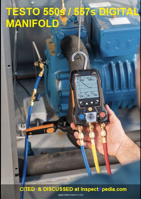
Illustration: testo 550s or 5557s Digital Manifold for measuring refrigerant pressures; Testo's equipment, cited below, includes models that can communicate refrigerant pressure readings wirelessly to a smartphone app.
- Testo 550s / 557s DIGITAL MANIOLD INSTRUCTION MANUAL [PDF] Testo SE & Co. KGaA Celsiusstr. 2 79822 Titisee-Neustadt Germany Phone: +49 (0)7653 681-0 E-mail: info@testo.de www.testo.com retrieved 2021/02/26 original source: https://static-int.testo.com/media/86/9b/837390b3094b/testo-550s-557s-Digital-Manifold-Instruction-Manual-US.pdf
...
Continue reading at REFRIGERANT PRESSURE READINGS & CHARTS or select a topic from the closely-related articles below, or see the complete ARTICLE INDEX.
Or see REFRIGERANT TEST GAUGE FAQs posted originally at this article
Or see these
Recommended Articles
- AIR CONDITIONER TEMPERATURE MEASUREMENT
- FROST BUILD-UP on AIR CONDITIONER COILS
- PRESSURE CONTROLS & SAFETY SWITCHES
- REFRIGERANT CHARGING PROCEDURE
- CAR / TRUCK AC PRESSURE SWITCH
- FROST BUILD-UP on AIR CONDITIONER COILS
- GAUGE, REFRIGERATION PRESSURE TEST
- REFRIGERANT CHARGING PROCEDURE
- REFRIGERANT DRIERS & FILTERS
- REFRIGERANT FLOODBACK, LIQUID SLUGGING
- REFRIGERANT LEAK DETECTION
- REFRIGERANT LEAK REPAIR
- REFRIGERANT LINE FROST or ICE
- REFRIGERANT METERING DEVICES TEVs & EEVs
- REFRIGERANT METERING CAPILLARY TUBES
- REFRIGERANT OVERCHARGE EFFECTS
- REFRIGERANT PIPING INSTALLATION
- REFRIGERANT PRESSURE DIAGNOSIS
- REFRIGERANT PRESSURE READINGS & CHARTS
- REFRIGERANT PROBLEM TYPES
- REFRIGERANT UNDERCHARGE EFFECTS
- REFRIGERANT SIGHT GLASS
Suggested citation for this web page
GAUGE, REFRIGERATION PRESSURE TEST at InspectApedia.com - online encyclopedia of building & environmental inspection, testing, diagnosis, repair, & problem prevention advice.
Or see this
INDEX to RELATED ARTICLES: ARTICLE INDEX to AIR CONDITIONING & HEAT PUMPS
Or use the SEARCH BOX found below to Ask a Question or Search InspectApedia
Ask a Question or Search InspectApedia
Try the search box just below, or if you prefer, post a question or comment in the Comments box below and we will respond promptly.
Search the InspectApedia website
Note: appearance of your Comment below may be delayed: if your comment contains an image, photograph, web link, or text that looks to the software as if it might be a web link, your posting will appear after it has been approved by a moderator. Apologies for the delay.
Only one image can be added per comment but you can post as many comments, and therefore images, as you like.
You will not receive a notification when a response to your question has been posted.
Please bookmark this page to make it easy for you to check back for our response.
IF above you see "Comment Form is loading comments..." then COMMENT BOX - countable.ca / bawkbox.com IS NOT WORKING.
In any case you are welcome to send an email directly to us at InspectApedia.com at editor@inspectApedia.com
We'll reply to you directly. Please help us help you by noting, in your email, the URL of the InspectApedia page where you wanted to comment.
Citations & References
In addition to any citations in the article above, a full list is available on request.
- Thanks to reader G.G. for technical comments regarding article text clarity, 12/30/2013.
- TIF Instruments, Inc., 9101 NW 7th Avenue, Miami, Florida 33150 (This is where we've sent our TIF 8800 and TIF 5000 for repairs).
- Refrigeration Temperature & Pressure Chart, web search 07/27/2011, Reece National Support Centre
118 Burwood Highway
Burwood Victoria 3125 Australia. The company also has offices in New Zealand.
Phone: +613 9274 0000
Fax: +613 9274 0198, original source: http://www.reece.com.au/plumbing/techtools/refrigerant - quoting from Reece:
Reece is Australia‘s leading supplier of bathroom and plumbing products with over 400 stores across the country including our market leading Bathroom Life™ showrooms. We also cater for more specialised industries through our Irrigation, hvac-r and Civil businesses as well Onsite which services commercial plumbers and volume home builders. - Refrigeration temperature & pressure chart for R-14, R14, tetrafluoromethane, also referred to as CF4, web search 07/27/11, original source http://encyclopedia.airliquide.com/Encyclopedia.asp?GasID=61#VaporPressureGraph
- Carbon fluoride; Freon 14; Perfluoromethane; Carbon tetrafluoride; Halocarbon 14; R 14; PFC 14 are synonyms for R14 refrigerant.
- In addition to citations & references found in this article, see the research citations given at the end of the related articles found at our suggested
CONTINUE READING or RECOMMENDED ARTICLES.
- Carson, Dunlop & Associates Ltd., 120 Carlton Street Suite 407, Toronto ON M5A 4K2. Tel: (416) 964-9415 1-800-268-7070 Email: info@carsondunlop.com. Alan Carson is a past president of ASHI, the American Society of Home Inspectors.
Thanks to Alan Carson and Bob Dunlop, for permission for InspectAPedia to use text excerpts from The HOME REFERENCE BOOK - the Encyclopedia of Homes and to use illustrations from The ILLUSTRATED HOME .
Carson Dunlop Associates provides extensive home inspection education and report writing material. In gratitude we provide links to tsome Carson Dunlop Associates products and services.
 | HOME | ABOUT | ASK a QUESTION | CONTACT | CONTENT USE POLICY | DESCRIPTION | POLICIES | PRIVACY | |
| © 2025 - 1985 Publisher InspectApedia.com - Daniel Friedman | |||||||||