
InspectAPedia® FREE Encyclopedia of Building & Environmental Construction, Diagnosis, Maintenance & Repair |
Question? Just ask us! InspectAPedia
|
 Building Water Flow Rate
Calculation & Measurement Procedures thanks to Shelly Weinberg

- POST a QUESTION or COMMENT about measurements of water flow rate at buildings & fixtures
Measure water flow rate: how to measure water quantity delivered per minute at building plumbing systems.
How to measure the water flow rate in gallons or liters per minute at building faucets & fixtures. Plumbing fixture flow rate data. Water flow rate vs pipe diameter & pressure. This article describes procedures for measuring the flow rate in gallons per minute or liters per minute at a building faucet or plumbing fixture.
We explain what fixture flow rate means and we warn that measuring water flow in or at a building may give quite misleading data about the condition of the building water supply whether it's from a private well or from a municipal water main.
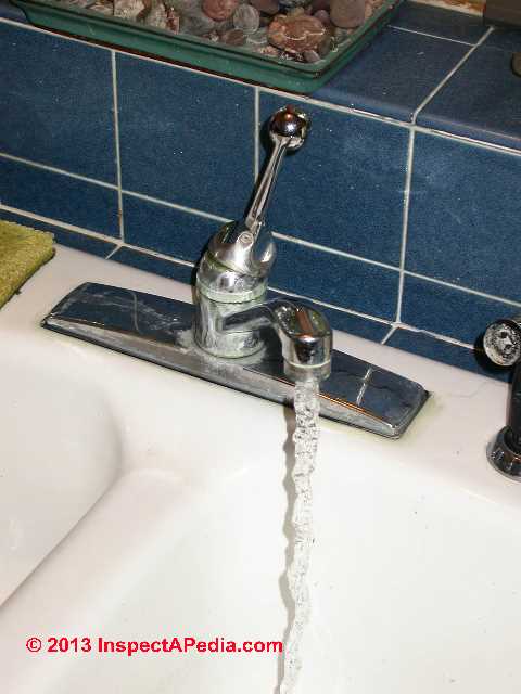
Our page top photo shows typical flow rate at a kitchen faucet - around 3 gpm.
InspectAPedia tolerates no conflicts of interest. We have no relationship with advertisers, products, or services discussed at this website.
- Daniel Friedman, Publisher/Editor/Author - See WHO ARE WE?
How to Calculate or Measure Actual & Theoretical Water Flow Rates in a Building
 Article Contents

- MEASURE ACTUAL FLOW RATE
- TYPICAL FLOW RATES AT PLUMBING FIXTURES
- NOMINAL FLOW RATES by PIPE DIAMETER
- CALCULATE WATER FLOW RATES for PIPE DIAMETER, LENGTH, PRESSURE
- SOURCES of FLOW RATE VARIATION
- WATER FLOW RATE & USAGE CONTROL
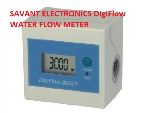
Above: a digital flow meter from Savant.
[Click to enlarge any image]
Empirical Flow Rate Measurement Using a Bucket & Stopwatch
 One can purchase flow meters like the Savant digital flow meter above and that connect to various plumbing fixtures to make water usage measurements,
and there are "flow meters" sold to home inspectors that pretend to make such a measurement at a sink tap, but remember that we are measuring the flow rate at the particular fixture - that number that does not describe the water flow rate capability of the water supply system nor the capacity of water that could be delivered to the building.
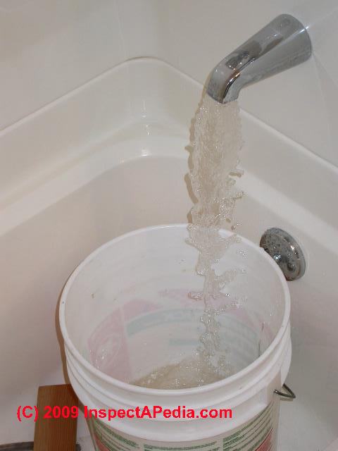
Our photo shows water running into a five-gallon plastic bucket. If this is the only fixture running water in the building we can time the number of seconds or minutes needed to fill the bucket.
For example, if the time required to fill the five gallon bucket is one minute, then the water flow rate at this plumbing fixture is 5-gallons per minute or 5 gpm.
Watch out: measuring "flow rate" at any faucet or fixture served by a well pump system will be inaccurate and will reflect pump capacity, piping restrictions, fixture restrictions, and even actual well flow rate variations where pump protection tailpieces or similar devices are installed. Measuring flow rate at a fixture does not measure the well's true flue rate.
The measurement of water flow rate at a particular plumbing fixture does not accurately measure the true water flow rate of the plumbing system because:
- Different flow rates will be found at individual fixtures
depending on the water flow restriction of the fixture itself, its' faucet strainer or even a disk that has been inserted into the faucet or shower head (for example) to deliberately restrict the water flow rate. - Water piping supplying a particular fixture may restrict flow rate
depending on the length and diameter of piping as well as possible hidden errors in the plumbing system such as a partial pipe blockage by solder at a copper joint, or blockage in the water supply piping if it is clogged by minerals or rust. - Water flow on a well pump and tank system will vary
during the measurement period depending on just when the water pressure drop turns the well pump on or off. - Pump protection device effects on flow rate:
Water flow rate on a well pump and tank system will also vary if the well flow rate or well recovery rate is also varying and if a well protection device such as a tailpiece is installed.
See WELL PIPING TAIL PIECE - Water pressure regulator settings
will affect any measurement of water flow rate at a building since the water pressure regulator setting might set a limit on the water flow rate through that control. Water pressure regulators are found at most buildings supplied with community or municipal water supplies (from water mains) and they may be found on private water supply systems, including on pump and well systems.
On a pump and well system when we turned on water at just the kitchen sink (DYNAMIC WATER PRESSURE) the flow rate dropped slowly until the pump turned on. Then the water pressure rose slowly until the pump turned off. Water pressure varied between 38 psi (pump off) and 25 psi (pump on).
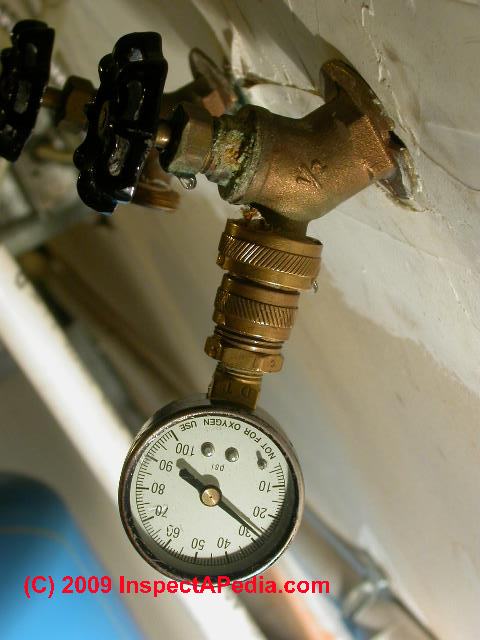
When we turned on water at a bath tub faucet (photo just above) water pressure dropped to about 28 psi and stayed there as the well pump ran continuously, delivering water to the building at that rate. Here is a photo of our PRESSURE GAUGE reading 28 psi [image]
Also see WATER PRESSURE REDUCER / REGULATOR for a discussion of how we reduce building water pressure to a safe level and how we assure uniform building water pressure and flow using a pressure reducing valve or pressure regulator.
Readers whose building is served by a private pump and well system should
see WATER PUMP PRESSURE CONTROL SWITCH.
Typical Building Water Flow Rates at Various Fixtures or Test Points
If we actually measure the flow rate at various building fixtures and faucets we will see water flow, measured in gallons per minute or liters per minute in these ranges:
Typical Water Flow Rates in Residential Properties |
||
| Plumbing fixture or measurement location | Water Flow Rate in GPM / LPM | Comments / notes |
| Bath tub faucet with no flow restrictor installed | 3-5 gpm | [1] |
| Bathroom sink faucet | 1-3 gpm | [1] |
| Kitchen sink faucet | 2-4- gpm | [1] |
| Outdoor hose bib | 3-6 gpm | [1] |
| Shower head, no flow restrictor | 2-6 gpm | [1] |
| Shower head with flow restriction device installed | 1.25 - 3.5 gpm | [1], average 2 gpm. |
| Shower heads prior to 1980 | 5 gpm (19 lpm) | |
| Shower heads, flow restrictors ca 1985 | 3.5 gpm | |
| Shower heads, flow restrictors, ca 1989 | 3.0 gpm | |
| Shower heads, flow restrictors, 1992 | 2.5 gpm (9.5 lpm) | US National Energy Policy Act 1992, requirement waived in 2010 |
| Shower head with high flow restriction device | 1.8 gpm | |
| Water pressure tank drain | 3-6 gpm | [1] |
Notes to the table above
[1] Typical field measurements by home inspectors
Typical incoming water pressure at residential properties ranges between 20 psi and 70 psi. At properties served by a private pump and well system the actual flow rate will vary continuously between the pump's cut-in rate and cut-out rate. All flow rates are also affected by pipe diameter, length, restrictions, and other factors including water turbulence and building height.
Aerating shower heads restrict water flow rate by adding air mixed in with flowing water to increase perceived water volume.
Atomizing shower heads restrict water flow rate by water turbulence to create very fine high velocity water droplets.
Shower head flow restrictors in simplest form consist of a disc insert with a small center hole to meter water flow.
Some non-restrictive and non-compliant shower heads may permit water flow rates as much as 10 gpm (38 lpm).
Nominal Flow Rates for Water Pipes
Below we show how to CALCULATE WATER FLOW RATES for PIPE DIAMETER, LENGTH, PRESSURE
But for a simple quick estimate of the nominal water flow rate range based on water pipe diameter, the table below gives nominal and maximum flows. Where there are two or more entries on a line in the table those data are from different sources. You'lls ee that there is a lot of variability in estimates of these pipe flow rates, as we explain below the table.
Nominal & Peak Water Pipe Flow Rates |
||
| Pipe Diameter | Flow Rate in GPM | |
| Nominal | Peak | |
| 1/2" | 14 2 | 21 2 |
| 3/4" | 23 2 | 36 2 |
| 1" | 16, 37 2 | 30 |
| 1 1/4" | 30, 62 2 | 35 |
| 1 1/2" | 40 | 70 |
| 2" | 65 | 120 |
| 2 1/2" | 80 | 170 |
| 3" | 120 | 270 |
| 4" | 250 | 500 |
| 6" | 500 | 1100 |
| 8" | 1000 | 2000 |
| 10" | 1500 | 3000 |
Notes to the table above
- These are very general "nominal" possible flow rates of water through pipes of various diameters. Quite obviously the actual flow rate will vary enormously depending on the pressure delivered at the water source, pipe material type, friction losses, bends and elbows and other restrictions, and changes in elevation or head or lift.
- These entries are for PVC pipe, Schedule 40 Assuming an average pressure of 20-100 psi and about 12 feet per second of flow velocity.
At gravity to low-pressure systems, these flow rates will be substantially less
These flow rates are for rigid pipe. For flexible pipe you'll need to reduce the estimated flow rates by about 3%
Source for these entries in the table
FlexPVC, WATER FLOW RATES VS PIPE DIAMETER [PDF] ADAPTED from data provided by FlexPVC, Tel: 1-888-PBC-FLEX, Web: flexpvc.com retrieved 2021/12/22 original source: https://flexpvc.com/Reference/WaterFlowBasedOnPipeSize.shtml
Watch out: The company notes: These 3 charts come from 3 different sources, and they all are just general guidelines. and should not be relied on as a precise source for information or as a substitute for engineering. - The difference between nominal or smaller number flow rates and peak flow rates is that for peak we assume high pressure and about 18 feet per second of water flow velocity
Calculate the Flow Rate for a Given Pipe Diameter, Pressure, & Length
As a crude and very general approximation, you can guess at the theoretival flow rate by either of two calculations:
Nominal water pipe flow rate: Diameter2 x 20
Formula for Calculating Water Flow Rate by Pipe Diameter
Velocity of water inside a pipe V = 0.408 x (Q / D2)
Where to perform the calculation you need to know any two of the following three parameters
V = Velocity of water in a pipe given in feet per second
Q = Flow rate of water inside the pipe in gpm
D = Pipe inside diameter in inches
There are numerous online calculators that permit you to calcculate the volume or mass flow rate and velocity based on pipe diameters, such as
- Pipe Water Velocity and Minimum Pipe Diameter, Washington State University, http://irrigation.wsu.edu/Content/Calculators/General/Pipe-Velocity.php (Dec. 2021)
This calculator uses the Water Velocity V-equation given above
- Pipe diameter and flow rate calculator - https://www.pipeflowcalculations.com/flowrate/calculator.xhtml (Dec. 2021)
Hazen-Williams Formula for Calculating Water Pressure Loss in a Pipe
Pressure Loss Ploss = 4.53 x L x [(Q/C)1.852 / D4.857 ]
Where
Ploss = loss due to friction, expressed in psi
L = Length of the pipe in feet
Q = Water flow rate inside the pipe in gpm
C = Pipe Coefficient ( a friction loss figure) given as
C PVC = 150
C Alumin w/Couplers = 120
C Galvanized Steel or Asbestos-Cement = 140
C Cast Iron or Old Steel = 100
D = Inside Diameter of the pipe in inches
Sources: Water Flow Rate & Pressure Loss in Pipe Equations & Data
- Onicon, VELOCITY TO GPM CONVERSION CHART [PDF] gives nominal pipe sizes and gpm flow rates for water flow velocities b etween 1 ft/sec and 12 ft/sec. Onicon, 11451 Belcher Road South, Largo, FL 33773 USA Tel +1 (727) 447-6140
Web: www.onicon.com Email: sales@onicon.com retrieved 2021/12/22 original source: https://www.onicon.com/wp-content/uploads/0868-5-Velocity-to-GPM-Chart-2-sided-04-18.pdf - WSU calculator for pipeline pressure loss given at http://irrigation.wsu.edu/Content/Calculators/General/Pipeline-Pressure-Loss.php who in turn quoted this Hazen-Williams equation from WSU Prosser - IAREC, 24106 N Bunn Rd, Prosser WA 99350-8694, 509-786-2226.
What is the flow rate of water out of a 6-inch diameter line at 90 psi static pressure?
 Reader Question:
Hi, we have a 6" water line with a static pressure of 90 psi. We want to put in a 6" stand pipe for truck filling at 1500gpm & 20psi. will that work? - Jim Mault
Reply: water & water pipe hydraulics give flow rate in feet per second, gallons per minute, etc.
Whew!. OK so it depends ... that "static" pressure of 90 psi is not going to give us a true answer to the flow rate in gpm you'll be seeing, since we don't know the effects of line length, friction losses, and number of bends, valves, or obstructions in your water line.
[Click to enlarge any image]
Really this is a hydraulics question. The true figures for water movement through piping are interesting and complex. For example, the velocity of water moving through piping (measured in feet per second or fps) is not uniform across the diameter of the pipe.
Water moves fastest in the middle and slows down at the edges of the cylinder or pipe walls - which makes sense if we think the walls impart friction losses on the water.
OK so we'll skip that. Here are some basics:
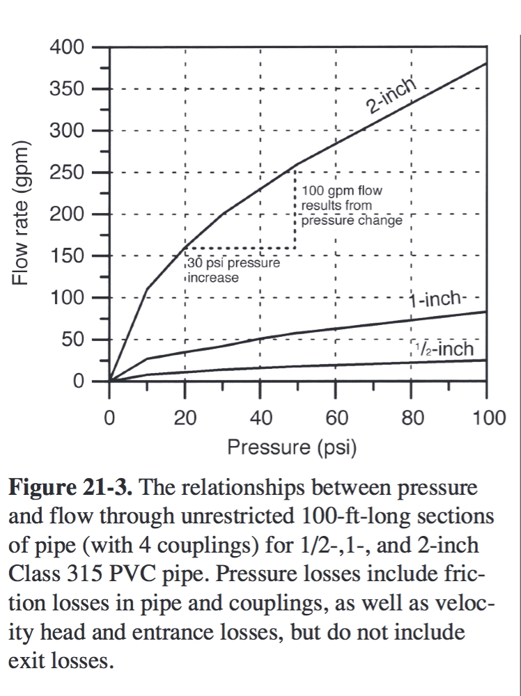
The cool chart at left relating water flow rate in GPM to pressure in psi makes some assumptions stated in the table's note.
This data is from engineering work prepared by the University of Florida, Indian River Research & Education Facility. - Dr. Brian Boman, "Chapter 21, Hydraulics", retrieved 3/3/2014, original source: http://irrec.ifas.ufl.edu/citrusbmp/ Water%20and%20FL%20Citrus/21%20Chap21.pdf
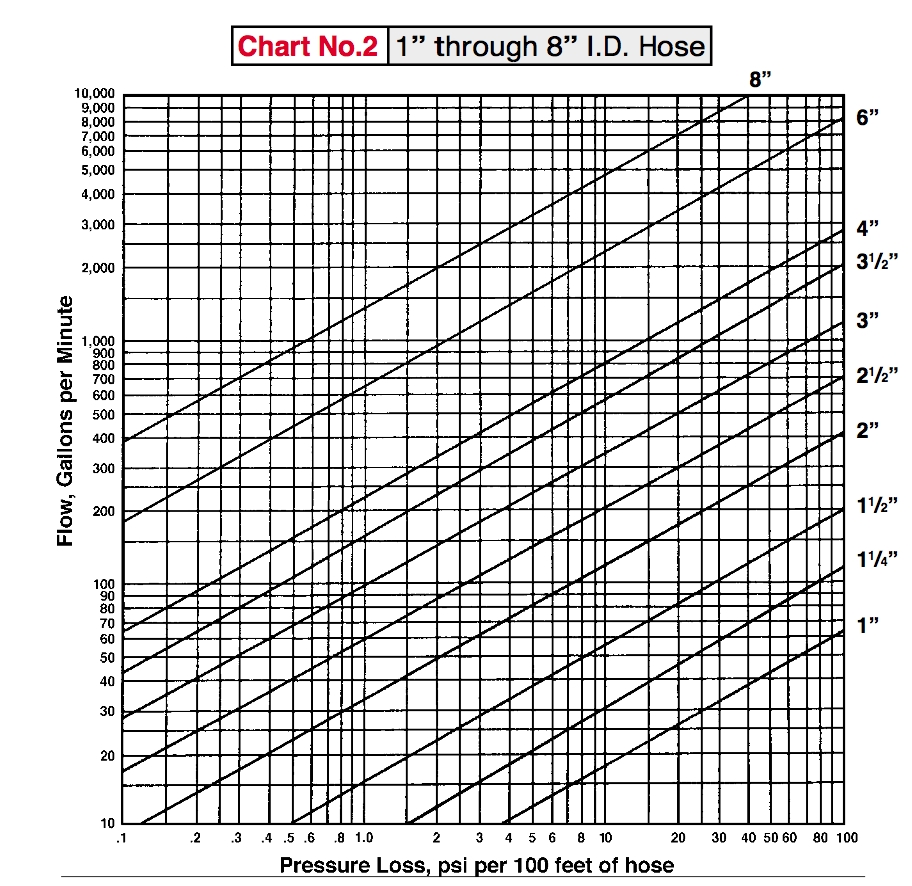
The second chart shown at left relates pressure loss to length for 100 feet of hose of various diameters up to greater than the 6-inch you asked about.
This data is from Dultmeier Sales also cited atReferences or Citations .
Click the chart to enlarge it for a more readable copy and you'll see that a six-inch diameter "pipe" (we don't know the material of your pipe) at a flow rate of 1500 gpm has a pressure loss of 4 psi per 100 feet.
From there and considering I've got no other data about your system, you are on your own to calculate the approximate flow rate loss for your system and thus the net flow rate.
You could ask Dultmeier or Dr. Boman for an accurate detail but I'm reluctant to bother an educator with these individual questions. Extrapolate from the table or try some basic ballpark calculations, or just give your local hydraulics engineer a call. Boman lays out the data and basic equation as follows:
Volumetric Flow Rate Calculation
 The equation of continuity states that
flow rate can be calculated from the multiple of the
velocity times the cross-sectional area of flow.
The equation of continuity states that
flow rate can be calculated from the multiple of the
velocity times the cross-sectional area of flow.
Definition of Volume Flow Rate
The volume flow rate Q, given by the equation below, is the volume of liquid that can pass through the cross-sectional area of a pipe over a given time interval.
The volume flow rate equation relates the cross-sectional area of the pipe (area of a circle of a given diameter if the pipe is round) and the time over which the flow occurs expressed usually as a velocity in feet per second.
Flow Rate Q = A x V or V = Q/A
or
Flow Rate Q = Volume / Time
where
- Flow Rate Q = flow rate in ft3 / second or cubic feet per second
or if we are using S.I. units, Q = flow rate in M3 / second or cubic meters per second - Area A = cross sectional area flow in sq. ft. of the pipe is given by two equivalent formulas:
Using the diameter of the pipe:
A = π x D2/4
where pi or π = 3.1416
D = Diameter or D2 = diameter squared
Using the traditional formula for area of a circle we use the radius of the circle.
From algebra we learned that the area of a circle
A = π r2
where r is the radius (half the diameter) of the circle
Because 2 x radius or 2r is exactly equal to D or diameter, both formulas are equivalent.
- V = velocity in ft/sec - for systems where V varies use the average fluid velocity in the pipe either in feet per second or in meters per second.
If we use feet per second then the volume flow rate will be in cubic feet per second
If we use meters per second then the volume flow rate will be in cubic meters per second. Or if you want cubic liters per second just divide meters/second by 1000.
Examples of Pipe Volume Flow Rates
Q = A x V for 1 meter per second through a 1-meter pipe
Shelly Weinberg, one of the greatest teaches I [DF] ever met, teaching at IBM's System Research Institute, was conducting a course in queuing theory. To demonstrate a service time optimization algorithm that looked daunting, Shelly asked us to pick any number and he would demonstrate how easy the calculation was.
The class sat mute, frozen.
"OK" Shelly said, "We'll pick ONE. ONE's a good number, right?"
In honor of Shelly Weinberg, let's set everything in the volume flow rate equation to 1 and see what happens.
A = 1 square meter cross sectional area of pipe
V = 1 meter per second flow rate
V = A x V or 1 x 1 = M3 / second
The flow of a fluid traveling at an average velocity of a 1 meter per second through a pipe with a 1 square meter cross-sectional area is 1 cubic meter per second - volumetric flow rate before considering fluid density.
Q = A x V for 1 foot per second through a 1-inch diameter pipe
A = π x D2/4
A = 3.1416 x 1 / 4
A = 3.1416
V = 1 ft. per second
Q = 3.1416 x 1
Q = 3.14 = ft3 / second or 3.14 cubic feet per second of volume flow rate
For building water supply systems and many other applications the above flow rate calculation is sufficient, but it is not accurate for all types of fluids of various densities.
Add Fluid Density to Flow Rate Calculations to Get Kilograms per Second Flow Rates
If we need to add consideration of fluid density on flow rates, Omega (cited below) explains:
W = rho x Q
where
- W = flow rate
- rho = fluid density
- Q = flow rate calculated before considering density
The flow rate will be 1 kilogram per second when 1 cubic meter per second of a fluid with a density of 1 kilogram per cubic meter is flowing.
As we've reported elsewhere under improving water flow in buildings or "perceived water pressure", doubling the pipe diameter increases the liquid carrying capacity of the pipe by a factor of 4.
FYI, friction losses for a 100 ft. length of 6" diameter PVC pipe are figured at 0.30 psi / 100 ft. of pipe. The friction loss data is different for different pipe materials, and is IMO always wrong for in-use systems where contaminants or usage have changed the surface properties of the piping to increase (roughing or wear or mineral deposits) or decrease (algae) friction losses.
Pressure Versus Flow is described eloquently by Boman. As I've struggled for years to explain this and to help people understand that what they call "water pressure" experienced at the kitchen sink or bath shower is better understood as flow rate, I'm quoting him here:
As water moves through any pipe, pressure is lost because of turbulence created by the moving water. The amount of pressure lost in a horizontal pipe is related to the velocity of the water, the inside diameter of the pipe, and the length of pipe through which the water flows. When velocity increases, the pressure loss increases.
For example, in a 1-inch Sch 40 PVC pipe with an 8-gpm flow rate, the velocity will be 2.97 fps with a pressure loss of 1.59 psi per 100 ft.
When the flow rate is increased to 18 gpm, the velocity will be 6.67 fps, and the pressure loss will increase to 7.12 psi per 100 ft of pipe.
Increasing the pressure in the system increases the flow rate. In Fig. 21-3, the flow rate in a 2-inch pipe increases by 100 gpm when the pressure is in- creased from 20 psi to 50 psi. Using a smaller pipe size does not increase the flow.
Note that the smaller pipe sizes have considerably less flow at any given pressure. Since decreasing the pipe size does not increase the pressure at the source, the result of decreased size is reduced flow.
Using a smaller pipe size does not increase pressure. In contrast, it will result in lower pressure because there will be greater pressure loss in the lines. In Fig. 21-3, a flow of 20 gpm would require about 9 psi pressure in a 1-inch pipe. In order to maintain a 20-gpm flow in a 1/2-inch pipe, over 50 psi would be required at the source. Smaller pipes result in greater pressure loss, not higher pressure. - Op. Cit.
Sources of Variation in Building or Fixture Water Flow Rate Measurements
Measurements of actual flow rate at a fixture (explained at MEASURE ACTUAL FLOW RATE) will not, without additional measurements, reflect variations due to changes in the source pressure such as the effects of a well pump and pressure tank or temporal variations in the water pressure delivered from a municipal source or variations in the behaviour of a pressure regulator.
If it takes 5 minutes to fill a 5 gallon joint compound bucket (that's what we used to use) at the bath tub, then we're seeing a water flow rate of one gallon per minute.
As we calculated at SUMP PUMPS, using an 18-inch diameter joint compound bucket (or sump pit of that size), one inch in the bucket equals 1.1 gallons of water. Therefore,
If our 5-gallon 18" diameter bucket is filled up 10 inches in one minute of running water, that gave us about 10 gallons (actually 11 gallons) of water "per minute" at that plumbing fixture.
What's wrong with measuring well flow rate in the building at the bath tub using a bucket and a stopwatch?
The water flow rate you observe at an individual plumbing fixture is affected by:
- The diameter, length, and number of bends in water supply piping between the well pump and the fixture outlet
- The state of any shutoff valves (partly closed) or clogs in the piping such as debris in a faucet strainer or shower head or scale in a toilet fill valve.
- For municipal water supply systems, the actual municipal water supply system pressure at the point of entry to your building, and water main pipe diameter (though the pipe size may be so big you don't care)
And of course the delivery pressure in municipal water systems is also not constant, varying by time of day and by individual community water supply system. - For well and pump systems, the point in the well pump on-off cycle during which you make the measurement - water pressure varies between the pump cut-in (typically 20 or 30 psi) and cut-out pressure (typically 40 or 50 psi as the pump turns on and off while water is running, so the flow rate is not constant.
See WATER PUMP PRESSURE CONTROL SWITCH.
And of course, the horsepower and condition of the well pump itself
Watch out: This bucket in the house well flow test assumes that the water flow rate at the plumbing fixture somehow reflects the water in-flow into the well too. This is a big mistake. Those figures could be totally different.
For example we could have a well with a horrible in-flow rate of .5 gpm but a huge water reservoir tank or a huge static head in the well itself.
The well or water flow rate we can measure at or inside of a building reflects the conditions of the pump, pressure tank, building piping, valves, and fixture, not the actual well flow rate of water from the ground into the well.
Nevertheless, an at-building water "flow test" is a practical or functional test that might tell you something important. At countless building inspections we ran water in the building, pulling perhaps 200 gallons or so out during a septic loading and dye test.
And at countless inspections we ran out of water, discovering that the well and water supply system had a poor well flow rate combined with a small static head in the wall and a small in-building water tank. But when you see a poor water flow in the building, you have found a problem but you have not diagnosed the problem.
Omega, a provider of accurate flow metering equipment adds these technical details about measuring water flow:
The fluid and its given and its pressure, temperature, allowable pressure drop, density (or specific gravity), conductivity, viscosity (Newtonian or not?) and vapor pressure at maximum operating temperature are listed, together with an indication of how these properties might vary or interact.
... Expected minimum and maximum pressure and temperature values should be given in addition to the normal operating values when selecting flow meters....
Concerning the piping and the area where the flowmeters are to be located, consider:
For the piping, its direction (avoid downward flow in liquid applications), size, material, schedule, flange-pressure rating, accessibility, up or downstream turns, valves, regulators, and available straight-pipe run lengths.
The specifying engineer must know if vibration or magnetic fields are present or possible in the area, if electric or pneumatic power is available, if the area is classified for explosion hazards, or if there are other special requirements such as compliance with sanitary or clean-in-place (CIP) regulations. - Omega, retrieved 11 Aug 2015, original source: http://www.omega.com/prodinfo/flowmeters.html
How to Control Water Flow Rates & Usage
How to Both Measure & Restrict Water Usage
Reader Question:
We are looking some sort of 'Auto valve/Flow meter' which will allow us to restrict the supply of water to each residential flat to a specified limit e.g. 200-300 liters per day. After supply of specified limit of water, valve should automatically close & stop the further flow of water. - kjsuryawanshi@bajajauto.co.in said:
Reply: control water usage by metering, timed valves, or sub-meters charging for actual water use
KJ
It is easy to measure the volume of water delivered to a specific residential flat provided that each flat receives all of its water from a single delivery pipe: install a water meter at each of those points. If however building hot water is provided from a central source though a separate piping network you may need two water meters to measure both hot and cold water use.
It is also easy to restrict water flow rate through piping using controls, valves, and low-flow plumbing fixtures.
But to restrict water usage to a specific quantity in cubic feet, gallons or liters is another matter. You'd need to combine a water metering device with an automatic shutoff valve. Or for a less costly approach you can install timers to control water supply valves, opening and closing the valves only during certain intervals - something that few of your residents will appreciate.
In our opinion best, is to control water usage by metering and charging individual water users by installing sub-meters. This approach encourages voluntary water conservation.
I suggest that before going to that considerable expense you invest in
- Finding and fixing water wasting leaks such as running toilets
- Installing low flow plumbing fixtures, toilets, shower heads, faucets
- See WATER CONSERVATION MEASURES
Sources of Water Flow Meters
Take a look at the Ista line of process and flow controllers as well as those made by other manufacturers listed below. Some of these flow meter producers such as Omega include flow control devices. See
BTU MONITORS & HEATING COST APPORTIONMENT for some examples.
- Belkin International, Inc. (offices world wide): low-cost home water flow and usage monitoring equipment, WeMo® Water, Tel: 1-800 223 5546, Website: http://www.belkin.com/ [Good luck finding an actual mailing address, but the company's website offers online communication.] Belkin produdes a wide range of computer and electronic cables, routers, switches, networking devices, power protectors and other electrical equipment.
- Dwyer Instruments, 102 Indiana Hwy. 212 (P.O. Box 373) Michigan City, IN 46360 (46361) USA Tel: 219/879-8000
- Dynaflox, Dynaflox Shanghai Co., Ltd.
No.106 Qianpu Road, Eastward New Area,Songjiang Industrial Zone,Shanghai
Tel: (86) 21-67602289
Fax: (86) 21-67602287
Email: info@dynaflox.com.cn
Sales:
North America, Africa: Lisa@dynaflox.com.cn
South America, Asia: Jocelyn@dynaflox.com.cn
East Europe, Middle East: Melody@dynaflox.com.cn
West Europe, Oceania: Sophia@dynaflox.com.cn
Dynaflox Shanghai Co., Ltd is a ... manufacturer of ultrasonic flow meter and ultrasonic water meter in China, ... in the field of ultrasonic meters for nearly 20 years. - Graftel, LLC, 870 Cambridge Drive
Elk Grove Village, IL 60007 USA Tel: 847-364-2600
Graftel maintains four NIST traceable primary liquid flow calibration systems utilizing water as the calibration medium. Each systems uses a high accuracy Coriolis meter as a secondary standard and its own gravimetric time-mass system as a primary standard. These four systems cover overlapping ranges so that they may be checked against each other.
Graftel maintains a complete calibration lab for gas flow, liquid flow, air velocity, RH/dew point and temperature. Calibration work is accredited to ISO/IEC 17025:2005, ANSI/NCSL Z540-1:1994 (R2002), and ANSI/NCSL Z540.3:2006 sub clause 5.3. Laboratory equipment is maintained in accordance with MIL-STD-45662A. Nuclear power applications meet 10 CFR 50 Appendix B and Part 21 requirements. Our QA program has been audited by many nuclear utilities and industrial customers. - Omega, OMEGA Engineering, Inc.
,One Omega Drive
P.O. Box 4047
Stamford, Connecticut 06907-0047
(800)-848-4286 or (203)-359-1660
Fax: (203)-359-7700 Tel: US and Canada
1-888-826-6342
International
1-203-359-1660
Email: cservice@omega.com Website: http://www.omega.com/
Excerpt:
A flow meter is an instrument used to measure linear, nonlinear, mass or volumetric flow rate of a liquid or a gas. When choosing flowmeters, one should consider such intangible factors as familiarity of plant personnel, their experience with calibration and maintenance, spare parts availability, and mean time between failure history, etc., at the particular plant site. It is also recommended that the cost of the installation be computed only after taking these steps.
The list of brands of flow metering equipment is long as you can see. Here are more flow metering manufacturers you can consult:
Aalborg, Alicat Scientific, AquaMetrix, AW Gear Meters, Badger Meter, Blancett, Dwyer Instruments, Dynasonics, Flocat, Flo-tech, Flowline, Fox Thermal Instruments, Fuji Electric, GE Panametrics, GE Rheonik, Gems Sensors & Controls, General Tools, Georg Fischer / GF Signet, GPI, Greyline Instruments, Hedland, KEP, King Instrument, Kobold, Krohne, Lake Monitors, Mace, Macnaught, Rosemount, Seametrics, Sondar, Teksco, Universal Flow Monitors, W.E. Anderson, Yokogawa
Watch out: Measurements like the
- WATER FLOW RATE CALCULATE or MEASUREMEASUREMENT - the flow rate of water at plumbing fixtures or faucets
- WATER PRESSURE MEASUREMENT - with what force does water exit at a fixture or
faucet
(DYNAMIC PRESSURE),
or what is the water pressure in a system when no water is being run
(STATIC PRESSURE) - WELL DEPTH, HOW TO MEASURE - how deep is the well
- WELL FLOW RATE - the well recovery rate or how much water can we take out of the well in a given time period
are all useful, but taken by themselves some of these numbers can give a false reading about the basic question of how much water is in the well?
Even calculations of theoretical flow rate through a pipe of given diameter, length, pressure, and bends
(explained at CALCULATE WATER FLOW RATES for PIPE DIAMETER, LENGTH, PRESSURE)
will not give the actual flow rate that will be experienced in most real-world situations where other details that affect flow rate have not been considered such as the effects of height, flow restricting fixtures, variations in the actual water source pressure, unidentified restrictions in piping such as mineral deposits or rust, etc.
Before assuming that a water pressure, flow, or quantity problem is due to the well itself,
see WATER PUMP REPAIR GUIDE for an example of diagnosis of the cause of loss of water pressure, loss of water supply, and analyzes the actual repair cost.
...
Reader Comments, Questions & Answers About The Article Above
Below you will find questions and answers previously posted on this page at its page bottom reader comment box.
Reader Q&A - also see RECOMMENDED ARTICLES & FAQs
Open pipe flow rate question.
Anyone know how to solve this problem?
A water flow test was done at Seneca College on July 31, 2017.
The static pressure was measured with no water flowing and was observed to be 75 pounds per square inch (psi). The 2.5" projected outlet was opened and water was allowed to flow at full capacity on the second hydrant.
The pitot reading was 50 psi. While the water was flowing, the flow pressure from the first hydrant was observed to be 65 psi.
How much water was flowing from the second hydrant? Graph your answer in the space provided. - On 2020-10-07 by James -
Reply by (mod) -
James
Yes we've had this question before. This is a fluid mechanics problem referred to as the open pipe flow rate question.
Our answer came from a reliable source, the engineering stack exchange at
https://engineering.stackexchange.com/questions/27036/open-pipe-and-relation-between-pressure-and-flow-rate
There are two approaches, depending on whether or not you're considering the length of pipe through which water is flowing;
If you know the length L then you apply Poiseuille's Law,
Poiseuille's Law,
𝐹𝑙𝑜𝑤=π⋅𝑟4⋅(𝑃−𝑃𝑜)8⋅η⋅𝐿𝑐𝑚3/𝑠
Assuming you have a Pipe with the area 𝐴𝑐𝑚2
𝐹𝑙𝑜𝑤=𝐴𝑟2⋅(𝑃−𝑃𝑜)8⋅η⋅𝐿𝑐𝑚3/𝑠
-P = pressure at the entrance, Bar
-P0 = atmosphere pressure, Bar
-eta = viscosity at dyne second/cm2 for water at 20c it is 0.01
-L = length cm.
but if you ignore length you apply the Bernoulli equation 𝑝+𝜌∗(𝑐2/2)+𝜌∗𝑔∗𝑧=𝑐𝑜𝑛𝑠𝑡𝑎𝑛𝑡
PS: Good luck on your test.
Water pressure from a 1/2 inch opening at the bottom of a tank
What would be the water pressure from a 1/2 inch opening at the bottom of a tank 5 feet in diameter and 10 feet high when full? -On 2019-03-11 by Chrissy -
Reply by (mod) -
Chrissy
The pressure exerted by water when measured at the bottom of a column of water is not dependent on the diameter of a column only the height of the column.
In the ARTICLE INDEX found above in the article titled at WATER PRESSURE MEASUREMENT
We
explain how to calculate the pressure at the bottom of a column of water of Any Given height. Since you probably don't want to go look in the way that I've described you can also jump directly to this link
https://inspectapedia.com/water/Water_Pressure_Measure.php#Height
Calculate the amount of water that could possibly be distributed to a home per day
How do you calculate the amount of water that could possibly be distributed to a home per day. Im not sure if I worded that correctly. - On 2018-07-16 by Matt -
Reply by (mod) -
Matt
You ask a perfectly good question, a great one, but one that is in my opinion very difficult to answer, because of the number of variables and the fact that no actual home will precisely fit any generic formula or answer.
The theoretical answer is given in the article above from which I will excerpt:
The equation of continuity states that flow rate can be calculated from the multiple of the velocity times the cross-sectional area of flow.
Q = A x V or V = Q/A
where
Q = flow rate in ft3 / second
A = cross sectional area flow in sq. ft. of the pipe
(A = π x D2/4 and of course pi or π = 3.1416)
V = velocity in ft/sec - for systems where V varies use the average fluid velocity in the pipe
The flow of a fluid traveling at an average velocity of a 1 meter per second through a pipe with a 1 square meter cross-sectional area is 1 cubic meter per second - volumetric flow rate before considering fluid density. .
For building water supply systems and many other applications the above flow rate calculation is sufficient, but it is not accurate for all types of fluids of various densities.
But for an actual home there are practical considerations that argue that the theoretical answer is likely to be wrong.
Even starting at a water pressure regulator, that device will pass more water volume (at the same pressure) as more faucets are opened in your home.
If we had just a single open pipe pouring water into a home, say at a bath tub, we could calculate the flow rate using an engineering approach that considers pressure and pipe diameter, but that's not the case in a normal home: you have many pipes with elbows, lengths variations in diameter, and constrictions at fixtures. Even the constrictions are not fixed over time
In addition, the pressure of water delivery from the municipal supply - if it is a municipal supply in your case (you don't say) - in many communities varies from hour to hour and day to day.
If your water supply is from a private pump and well system, the delivery pressure is not fixed, by cycles from a low CUT IN pressure to a higher CUT OUT pressure, and worse, the cycle time will vary widely depending on how many fixtures are being run simultaneously, unless and until you are running so much water that the pump simply runs continuously.
In that case you've reached the delivery limit for the private pump and well.
So what's to be done to guesstimate how much water could possibly be delivered:
You could calculate the potential flow rate at your entering water main at your building by assuming a fixed pressure and diameter and by removing the pipes at the incoming main, say just past the shutoff valve.Then you'd open the valve and measure the pipe diameter and the dimensions of the arc of the stream of water. There are engineering procedures to translate that arc and the other measurements into a fair estimate of flow rate.
Or you could read your water meter over some period of time to see your actual, not your theoretical maximum water usage rate.
Or you could run water at every fixture in your home at once, emptying the flow into a measured container - say a 5 gallon bucket - and time the minutes to fill each bucket. Those flow rates would be additive and would guess at what your house flow rate sum could be for the fixtures you test.It'll be incomplete as you'll find doing that with a washing machine or toilet or dishwasher is just too much trouble.
...
Continue reading at WATER PRESSURE VARIATION CAUSES or select a topic from the closely-related articles below, or see the complete ARTICLE INDEX.
Or see WATER FLOW RATE FAQs - questions & answers on how to measure or calculate the flow rate of water from a well or through a pipe
Or see these
Recommended Articles
- CALCULATE WATER FLOW RATES for PIPE DIAMETER, LENGTH, PRESSURE
- CLOGGED SUPPLY PIPES, DIAGNOSIS
- HOT WATER PRESSURE IMPROVEMENT
- HOT WATER QUANTITY IMPROVEMENT
- PEX BRASS CONNECTOR LEAKS build-up in brass elbows & tees that can clog PEX piping systems
- WATER FLOW RATE CALCULATE or MEASURE
- WATER PRESSURE BOOSTER PUMP
- WATER PRESSURE MEASUREMENT - what is the dynamic or static water pressure in a water supply system of faucets, fixtures, pipes, tanks, pumps, meters, pressure regulators?
- WATER QUANTITY IMPROVEMENT - steps to increase well yield or other means to improve water flow into the well itself
- WATER SUPPLY PIPE DIAMETER vs FLOW
- WATER CONSERVATION MEASURES - how to conserve or reduce water usage and water wastage
- WATER METERS, RESIDENTIAL
- WELL FLOW RATE - how much water can we actually get out of a well, at what rate, for how long?
Suggested citation for this web page
WATER FLOW RATE CALCULATE or MEASURE at InspectApedia.com - online encyclopedia of building & environmental inspection, testing, diagnosis, repair, & problem prevention advice.
Or see this
INDEX to RELATED ARTICLES: ARTICLE INDEX to WATER SUPPLY, PUMPS TANKS WELLS
Or use the SEARCH BOX found below to Ask a Question or Search InspectApedia
Ask a Question or Search InspectApedia
Try the search box just below, or if you prefer, post a question or comment in the Comments box below and we will respond promptly.
Search the InspectApedia website
Note: appearance of your Comment below may be delayed: if your comment contains an image, photograph, web link, or text that looks to the software as if it might be a web link, your posting will appear after it has been approved by a moderator. Apologies for the delay.
Only one image can be added per comment but you can post as many comments, and therefore images, as you like.
You will not receive a notification when a response to your question has been posted.
Please bookmark this page to make it easy for you to check back for our response.
IF above you see "Comment Form is loading comments..." then COMMENT BOX - countable.ca / bawkbox.com IS NOT WORKING.
In any case you are welcome to send an email directly to us at InspectApedia.com at editor@inspectApedia.com
We'll reply to you directly. Please help us help you by noting, in your email, the URL of the InspectApedia page where you wanted to comment.
Citations & References
In addition to any citations in the article above, a full list is available on request.
- Abdallah, Adel M., and David E. Rosenberg. "Heterogeneous Residential Water and Energy Linkages and Implications for Conservation and Management." Journal of Water Resources Planning and Management 140, no. 3 (2012): 288-297.
- Ghisi, Enedir, and Daniel F. Ferreira. "Potential for potable water savings by using rainwater and greywater in a multi-storey residential building in southern Brazil." Building and Environment 42, no. 7 (2007): 2512-2522.
- Hackett, M. J., and N. F. Gray. "Carbon dioxide emission savings potential of household water use reduction in the UK." Journal of sustainable development 2, no. 1 (2009): p36.
- McMahon, James E., Camilla Dunham Whitehead, and Peter Biermayer. "Saving water saves energy." Lawrence Berkeley National Laboratory (2006).
- Reiss, H., and A. Bolcs. "Experimental study of showerhead cooling on a cylinder comparing several configurations using cylindrical and shaped holes." Journal of turbomachinery 122, no. 1 (2000): 161-169.
- Opitz, Eva M., Jack C. Kiefer, William Y. Davis, Benedykt Dziegielewski, and John Olaf Nelson. Residential end uses of water. Denver, CO: AWWA Research Foundation and American Water Works Association, 1999.
- Renwick, Mary E., and Sandra O. Archibald. "Demand side management policies for residential water use: who bears the conservation burden?." Land Economics (1998): 343-359.
- Vickers, Amy. "Water-use efficiency standards for plumbing fixtures: benefits of national legislation." Journal (American Water Works Association) (1990): 51-54.
- White, S. B., and S. A. Fane. "Designing cost effective water demand management programs in Australia." Water Science & Technology 46, no. 6 (2002): 225-232.
- Brian Boman, "Chapter 21, Hydraulics", University of Florida, Indian River Research & Eductation Facility, 2199 South Rock Road, Fort Pierce, Florida 34945-3138 Tel: (772) 468-3922, Email: bjbo@ufl.edu, retrieved 3/3/2014, original source: http://irrec.ifas.ufl.edu/citrusbmp/ Water%20and%20FL%20Citrus/21%20Chap21.pdf
- Dultmeier, "Flow Data, Water Through Hose", Dultmeier Sales, Nebraska: 13808 Industrial Road, Omaha, NE 68137, Tel: 800 228-9666 and in Davenport IA, (800) 553-6975, Email: sales@dultmeier.com, Website: http://www.dultmeier.com/, Retrieved 3/3/2014, original source http://www.dultmeier.com/pdfs/tech-library/02Water8.pdf
- Watts, 815 Chestnut Street, North Andover, MA, USA 01845-6098, web search 09/18/2010 Watts Regulator Corporation, 815 Chestnut Street, North Andover, MA, USA 01845-6098, provides pressure and temperature relief valves, water pressure test gauges, water pressure regulators, backflow preventers, check valves, and other plumbing and heating controls and supplies. Website: http://www.watts.com/
- Engineering toolbox properties of water - http://www.engineeringtoolbox.com/water-thermal-properties-d_162.html editor.engineeringtoolbox@gmail.com web search 09/16/2010
- SI Metric.co.uk provides tables and constants for the properties of water - web search 09/16/2010 original source: http://www.simetric.co.uk/si_water.htm
- Wikipedia on the Density of water at 1 atmosphere, web search 09/16/2010, original source: http://en.wikipedia.org/wiki/Density
- In addition to citations & references found in this article, see the research citations given at the end of the related articles found at our suggested
CONTINUE READING or RECOMMENDED ARTICLES.
- Carson, Dunlop & Associates Ltd., 120 Carlton Street Suite 407, Toronto ON M5A 4K2. Tel: (416) 964-9415 1-800-268-7070 Email: info@carsondunlop.com. Alan Carson is a past president of ASHI, the American Society of Home Inspectors.
Thanks to Alan Carson and Bob Dunlop, for permission for InspectAPedia to use text excerpts from The HOME REFERENCE BOOK - the Encyclopedia of Homes and to use illustrations from The ILLUSTRATED HOME .
Carson Dunlop Associates provides extensive home inspection education and report writing material. In gratitude we provide links to tsome Carson Dunlop Associates products and services.
 | HOME | ABOUT | ASK a QUESTION | CONTACT | CONTENT USE POLICY | DESCRIPTION | POLICIES | PRIVACY | |
| © 2024 - 1985 Publisher InspectApedia.com - Daniel Friedman | |||||||||