
InspectAPedia® FREE Encyclopedia of Building & Environmental Construction, Diagnosis, Maintenance & Repair |
Question? Just ask us! InspectAPedia
|
 Duct Routing & Support Specifications
HVAC Ductwork installation errors & repairs
- POST a QUESTION or COMMENT about proper HVAC duct routing and support
Air duct routing & support mistakes to avoid:
This HVAC duct design and repair article describes proper (and improper) Heating & Air Conditioning Duct Routing & Support such as duct routing and support details to prevent or fix loose, sagging, crimped, bent or otherwise defective heating or cooling ductwork.
Crimped, squashed, or sagging ductwork restricts cooling or heating airflow into a building. Air ducts routed in a concrete floor slab also invite many problems including air quality issues and collapsed ductwork that reduces airflow and increases system operating cost.
InspectAPedia tolerates no conflicts of interest. We have no relationship with advertisers, products, or services discussed at this website.
- Daniel Friedman, Publisher/Editor/Author - See WHO ARE WE?
HVAC Air Duct Routing & Support Errors & Guide to troubleshooting
Air conditioning duct system defects include a remarkably wide range of errors, from failure to supply cool air or failure to even circulate air in the building, to health hazards such as use of asbestos material in or on duct work, to very dangerous conditions such as drawing heating equipment combustion gases into the building cooling (or heating) air.
This article describes errors to avoid when installing ductwork in buildings.
Avoiding these errors will result in improved air flow, lower system operating cost, and may help in avoiding problems of mold or other contaminants in the heating or cooling duct system of a building.
The master document, of which this is a chapter, describes the inspection of residential air conditioning systems (A/C systems) to inform home buyers, owners, and home inspectors of common cooling system defects and repairs.
Sketches adapted from GA recommended construction code & from: [13][14][15][16]
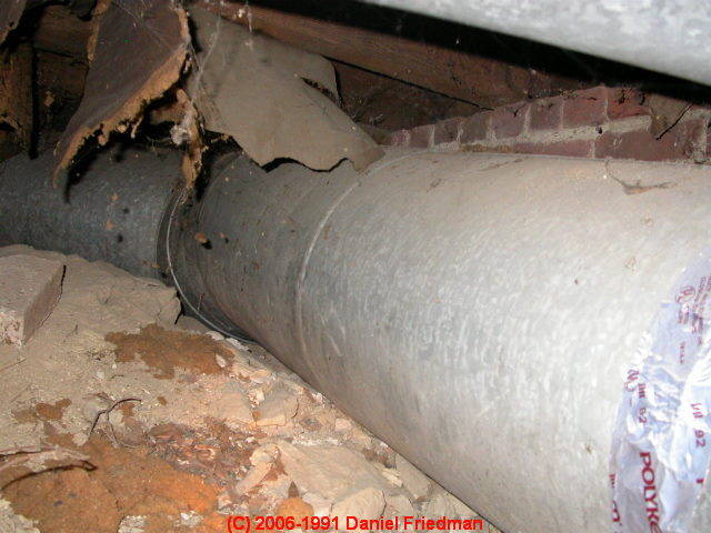
HVAC Ducts in ground contact

When heating and cooling ducts are placed in ground contact, such as in the crawl space shown in the photo, not only is the contact going to conduct heat or cooling away from the duct before the air reaches its destination.
Furthermore there is a significant risk of water leaks or accumulation of condensation in the duct in damp or flooding areas (risking a mold or health concern) or rodent entry.
Heating or cooling air ducts should be supported away from ground contact such as in crawl spaces.
Sharp Bends in Air Conditioning or Heating Duct Work Reduce Airflow
Sharp bends in ductwork restrict airflow (and violate ASHRAE or SMACNA guidelines for duct installations).
Restrictions in airflow through duct systems increase the heating or cooling system operating cost and reduce the comfort of building occupants.
This photograph shows flex-duct in an attic making a too-tight 180 degree turn, crimping and restricting airflow in the duct system.
Bends in flex duct should not be acute and should not be less than one duct diameter in radius - Sources: [13][14][15][16]
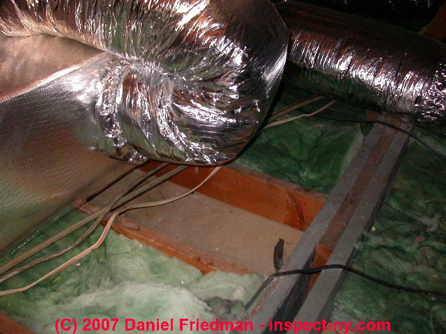
Excessive or Unnecessary Duct Lengths Increase Cooling or Heating Cost

Excessive length of ducts is often found where flex-duct is installed by an amateur. If you see a length of flex-duct snaking across an area with multiple unnecessary twists and turns, the combination of length and unnecessary bends reduces airflow, with the costs just cited above.
This photograph shows unnecessary lengths of small-diameter flex duct left by the installer. The small diameter of these ducts also tells us that we're looking at a high-velocity air conditioning system that uses a combination of small-diameter ducts and higher air velocity to deliver cooling air to the conditioned space.
Flex duct runs should be as short and direct as possible without at the same time causing inappropriately sharp bends or kinks. - Sources: [13][14][15][16]
See also HIGH VELOCITY HVAC DUCTS
HVAC air duct kinks & sharp bends restrict airflow
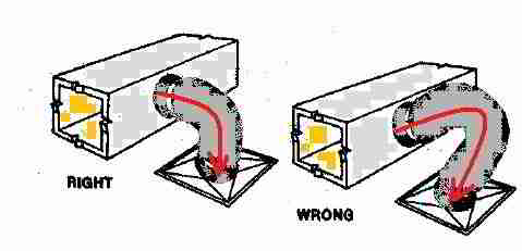
Flex duct runs should be as short and direct as possible without at the same time causing inappropriately sharp bends or kinks.- Sources: [13][14][15][16] Illustration adapted from [13].
The smoothness of the duct interior (flex duct is more resistant to airflow than a solid duct surface) is affected by the degree of flexduct extension. ACCA Manual D includes a friction chart that takes this into consideration (Appendix 2, chart 7).
Incidentally, when installing a length of flexduct, you should not just leave extra duct length "squashed" and in the run. Duct calculations assume that you have removed excess length of flexduct and that the installed length of flex-duct has been "fully extended".Why? For duct interior smoothness and better airflow. Fully extended flex duct will significantly redue the friction losses in the sysem.
Flexible Ductwork Support Specifications
Pinched or Crimped Air Ducts Reduce Heating or Cooling Airflow
Other common duct routing errors include sharp bends in duct work, mismatched sizes of duct work among sections, flex duct which has become crimped or pinched to restrict air flow such as in the photo at left, and of course ducts which have become disconnected.
We discuss and illustrate disconnected heating or air conditioning duct defects
at DUCT CONNECTIONS.
We show the interior of crimped or squashed flexduct
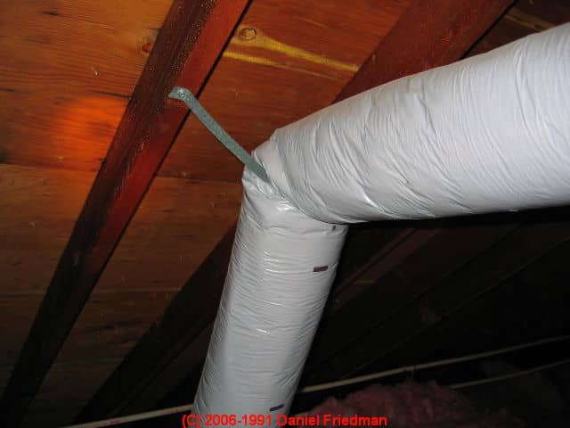
The photo at left violates several of the flex-duct installation guidelines we cite just below:
Flexible duct shall be supported at manufacturer’s recommended intervals, but at no greater distance than 5 feet (1524 mm). Maximum permissible sag is ½ inch per foot of spacing between supports.
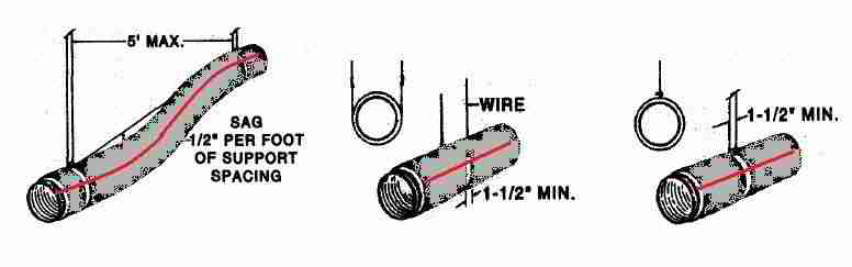
Hanger or saddle material in contact with the flexible duct should be of sufficient width (minimum 1 ½” (38 mm)) to prevent any restriction of the internal diameter of the duct when the weight of the supported section rests on the hanger. Individual ducts should be separately supported.
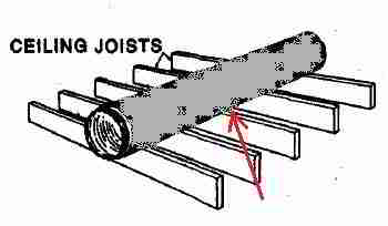
Flexible ducts may rest on ceiling joists or truss supports. Maximum spacing between supports should not exceed the maximum spacing per manufacturer’s installation instructions.
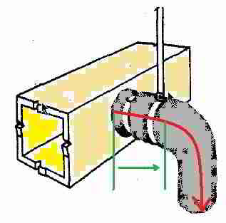
Support the duct between a metal connection and a bend by allowing the duct to extend straight for a few inches before making the bend.
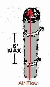
Vertically installed duct should be stabilized by support straps at a maximum of 6 feet (1829 mm) on center.
Also, for cool air distribution from a blower assembly located below the area served, the height of ductwork determines how much cold air the blower has to push "up" - don't use flex-duct for vertical air supply risers past more than two floors in a building.
- Sources: [13][14][15][16]
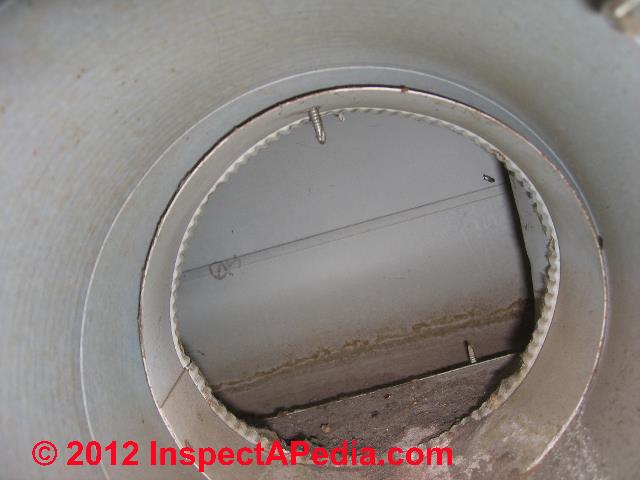
HVAC Ducts in Concrete Floor Slabs are trouble
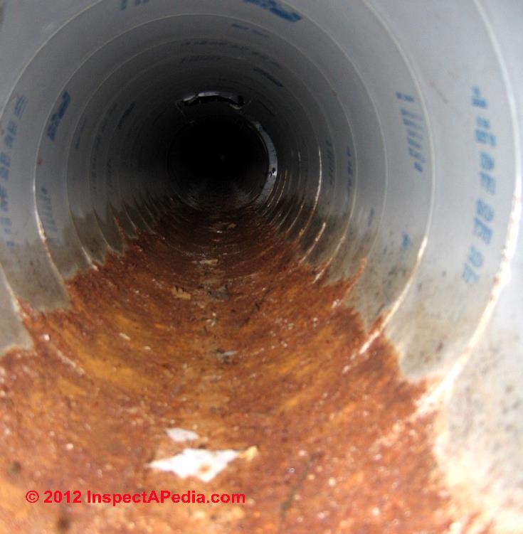
Our photo (below left) illustrates how you may spot an air duct routed through the building floor slab. In this case the furnace return air plenum was also located below the concrete floor. The air duct system in this building had been subject to periodic flooding, as illustrated in our second photo (below right).
A description of the health and functional problems that may be traced to air ducts that were routed in a concrete floor slab as well as our advice on how to properly abandon and seal in-slab air ducts are found at DUCT in CONCRETE FLOOR.

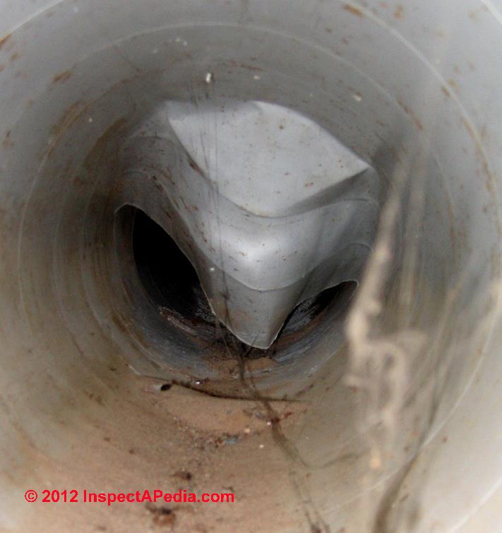
There we describe concerns with ductwork run in floor slabs in the article above, including risks of air duct collapse that interferes with air flow through the system, water leaks into the in-slab duct system (not a problem unique to transite ducts), and rodent or insect infestations or even mold contamination.
Odor complaints may be traced to the duct system because of these problems.
See details at DUCT & AIR HANDLER ODORS
Below, reader-contributed photographs of problems in spiral metal ductwork routed in a concrete floor slab illustrate rust, flooding history (below left) and ductwork collapse (below right).
We discuss and illustrate disconnected heating or air conditioning duct defects
at DUCT CONNECTIONS. We also show the interior of crimped or squashed flexduct
Hopefully needless to say,
flex duct should never be buried underground nor set into concrete slabs. [13]
SLAB DUCTWORK - catalogs the functional and environmental problems found when HVAC air ducts are routed in or below floor slabs
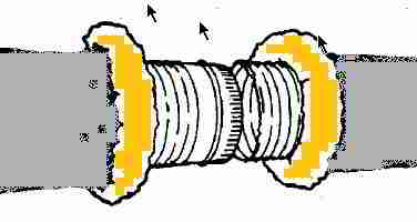
Flex Duct Connection & Splicing Specifications
- All connections, joints and splices should be made in accordance with the manufacturer’s installation instructions.
- All tapes, mastics and non-metallic fasteners (plastic clamps) used for field installation of flexible ducts should be listed and labeled to UL 181B, Closure Systems for Use With Flexible Air Ducts and Air Connectors. Non- metallic fasteners are limited to 6 inch w.g. (water gauge) maximum positive pressure.
- Sheet metal collars to which flexible ducts are attached should be a minimum of 2 inches (50.8 mm) in length and should be beaded.
- Sheet metal sleeves used for joining two sections of flexible duct should be a minimum of 4 inches (101.6 mm) in length and should be beaded on both ends.
- Sources: [13][14][15][16] Illustration adapted from [13].
Flex Duct Installation Specifications & Recommendations
Angel, I think you are asking what is the maximum recommended length for flexduct in an HVAC system.
Flexible air duct systems should be sized and designed in accordance with ACCA Manual D for residential duct systems or other ICC referenced engineering standards. An engineering answer to the question of HVAC duct design length restrictions for a specific installation would have to consider the resulting air flow through the system, determined by a number of factors including:
- a calculation of the required heating or cooling load for the room served by the duct
- the supply air that the room requires
- the static air pressure provided by the air handler blower
- a translation of all of the duct bends, fittings, and terminal devices (supply air control registers) into an equivalent "length of ductwork)
- the duct diameter (which you did not specify),
- the number of turns or bends (those reduce air flow rate). Bends in flex duct should not be acute and should not be less than one duct diameter in radius; and we are assuming there are no squashed, crimped, nor disconnected duct sections.
- the smoothness of the duct interior (flex duct is more resistant to airflow than a solid duct surface)
- the blower fan capacity in cubic feet per minute.
- for cool air distribution from a blower assembly located below the area served, the height of ductwork determines how much cold air the blower has to push "up" - don't use flex-duct for vertical air supply risers past more than two floors in a building.
Adding to all that complexity are other factors that can snarl up the delivery of air flow by a heater or air conditioner into a room, such as
- the presence or absence of return air ducts in the same room,
- their locations or placements on floors, walls, ceilings, and
- where central air returns are used, how easily air can flow out of individual rooms to the central air return.
OK so those are a bunch of factors that tell us how well a duct system will work.
But there are more: assuming you are describing using flex-duct to deliver air to a single supply register in some building room, is the flex duct routed directly to the room from the supply plenum, or did the designer include a larger diameter trunk line that brings conditioned air to the general area of the building, from which you are using a smaller diameter flex duct to get from the trunk line over to the actual air supply register?
Flex duct run length rule of thumb
In addition to duct design calculators and worksheets provided by duct manufacturers and HVAC industry associations, people often also do a "sanity check" on the duct design by applying a rule of thumb - much as you are asking about in your question:
The routing and length of flexible duct, the numbers of degrees of each bend and the amount of sag allowed between support joints will have serious effects on system performance due to the increased resistance each introduces. Use the minimum length of flexible duct to make connections. Do not install excess lengths of ducts to allow for possible future relocations of air terminal devices.
Flexible air duct trunk lines should not be limited in length. It is recommended as a guide that flexible air duct branch takeoffs (run-outs), flexible air ducts direct to boots from the plenum and flexible ducts in radial duct systems be limited in length to 25 feet (7620 mm). The preferred duct geometry is a “Trunk and Branch” system (see ACCA Manual D Figures 1-4 and 10-7).
... Terminal devices [air supply registers] should be supported independently of the flexible duct.
- using the International Mechanical Code & the Georgia state construction codes [13] as an example.
...
Reader Comments, Questions & Answers About The Article Above
Below you will find questions and answers previously posted on this page at its page bottom reader comment box.
Reader Q&A - also see RECOMMENDED ARTICLES & FAQs
Wouldn't it make more sense to leave hot air up at the ceiling?
I have a question in regards to cooling a large manufacturing plant. All of our machines give off a significant amount of heat.
All of this heat rises and is stagnate at the ceiling.
I know I could add Big Ass Fans, but why would you want to recirculate that hot air and mix it with the cool air below? I could always evacuate the hot air at the ceiling intermittently.
Wouldn't it make more sense to leave the hot air up there and move the cold air returns below the level of hot air? The cold air returns are currently sucking in hot air at the ceiling and trying to cool it back down! On 2020-07-28 by Darryl Johnson
by (mod)
You're quite right that hot air will stratify up near the ceiling and if there are not circulating fans, depending on ceiling height it may not mix much with air below.
But I'm reluctant to pretend I can offer an engineered solution: I'd want an onsite HVAC engineer or experinced tech to take a look at your building including ceiling heights, air handlers, duct systems.
I think our flex ducts are crushed from later insulation installation
8 inch flex ducts,garage door pulls shut when fan comes on,most air flow is at dinning room straight out of furnace-24 feet.
other ducts have very little airflow. Could ducts be crushed as I suspect from a later installation of 8 inch fiberglass bats.Also is their a way to expand ducts from ceiling vents? Thank you jlh On 2019-09-19 by Jim Helman
by (mod) -
It could be that your flex duct is crushed but it's also possible that if there's not adequate return air and you're talkin about a return. To could be crushing a ductwork
Don't confuse high velocity duct lengths and don't forget minimum duct lengths for sound attenuation
The picture labeled "excessive lengths" is a HIGH VELOCITY system, and several manufacturers SPECIFY A MINIMUM LENGTH for each take-off for sound attenuation.
They also manufacture their own small diameter duct in a different manner than "flex duct", allowing for more controlled air flow. On 2017-01-04 by HVAC Trainer
Fllexducting run by most installers at least in california are a myriad of errors and problems.
Its blow -n- go as usually the norm. Like the aluminum ground wire in the electrical panel for the main ground. Must have been the general contractor and city hacks in collusion, the whole tract has one or more issues./...
Here it is ..The assembly and filter with return air openings ....We need #2 with an area of 490 sq.In min. 20x16 + 14x14 =516cu.In
For 21/2ton unit requires min, of 483cu,in of
Return air cfm for proper combustion and effectiveness [less operatting cost] while in operation ....Will run this by jay ...
by (mod) -
Thanks HVAC, Spot on and good point.
I'd welcome further comment, source citation, references. That'd help other readers.
Perhaps you'll agree, however, that a very common snafu in flex-duct systems is the use of unnecesssary, extra lengths of flex duct that restrict air flow, reduce the system effectiveness, and increase operating cost. The flex duct manufacturers and standards I've reviewed make a specific point of telling the installer to cut off unnecessary lengths of flexduct rather than leave it flopping around.
How much efficiency do I lose if air returns are not located close to the floor
My house is one story on a slab, 1600sq ft. I am converting froms electric baseboard to a gas forced hot air system. All ducts are located in the attic. Since the return ducts will also be in the ceiling how many returns should I have the contractor install? How much efficency will I loose because the returns cannot be located close to the floor? - bricksenior@hotmail.com 5/29/11
Reply:
I agree that you're asking an important question about proper supply and return duct design, but I cannot answer it by email and with so little information. I'd ask the contractor to go over the design with you and to show you how the return air and supply air will be both adequate and balanced.
Also pay attention to the locations of the supply and return registers - you don't want the return too close to the supply or you'll have a short circuit in the system that will prevent good operation.
I also agree that pulling cool air from close to floor level is preferable to pulling it from a ceiling, but I don't know an actual efficiency number. In part that's because you need to consider the effect of good (versus poor) location and distance between supply and return outlet and inlet.
...
...
Continue reading at FLEX DUCT SOURCES & HISTORY or select a topic from the closely-related articles below, or see the complete ARTICLE INDEX.
Or see these
Recommended Articles
Suggested citation for this web page
DUCT ROUTING & SUPPORT at InspectApedia.com - online encyclopedia of building & environmental inspection, testing, diagnosis, repair, & problem prevention advice.
Or see this
INDEX to RELATED ARTICLES: ARTICLE INDEX to HVAC DUCT SYSTEMS
Or use the SEARCH BOX found below to Ask a Question or Search InspectApedia
Ask a Question or Search InspectApedia
Try the search box just below, or if you prefer, post a question or comment in the Comments box below and we will respond promptly.
Search the InspectApedia website
Note: appearance of your Comment below may be delayed: if your comment contains an image, photograph, web link, or text that looks to the software as if it might be a web link, your posting will appear after it has been approved by a moderator. Apologies for the delay.
Only one image can be added per comment but you can post as many comments, and therefore images, as you like.
You will not receive a notification when a response to your question has been posted.
Please bookmark this page to make it easy for you to check back for our response.
IF above you see "Comment Form is loading comments..." then COMMENT BOX - countable.ca / bawkbox.com IS NOT WORKING.
In any case you are welcome to send an email directly to us at InspectApedia.com at editor@inspectApedia.com
We'll reply to you directly. Please help us help you by noting, in your email, the URL of the InspectApedia page where you wanted to comment.
Citations & References
In addition to any citations in the article above, a full list is available on request.
- [1] Thanks to Mark Cramer, Tampa Florida, for assistance in technical review of the "Critical Defects" section and for the photograph of the deteriorating gray Owens Corning flex duct in a hot attic. Mr. Cramer is a Florida home inspector and home inspection educator.
- [2] Thanks to Jon Bolton, an ASHI, FABI, and otherwise certified Florida home inspector who provided photos of failing Goodman gray flex duct in a hot attic.
- [3] Air Diffusion Council, 1901 N. Roselle Road, Suite 800, Schaumburg, Illinois 60195, Tel: (847) 706-6750, Fax: (847) 706-6751 - Email: info@flexibleduct.org - www.flexibleduct.org/ -
"The ADC has produced the 4th Edition of the Flexible Duct Performance & Installation Standards (a 28-page manual) for use and reference by designers, architects, engineers, contractors, installers and users for evaluating, selecting, specifying and properly installing flexible duct in heating and air conditioning systems.
Features covered in depth include: descriptions of typical styles, characteristics and requirements, testing, listing, reporting, certifying, packaging and product marking.
Guidelines for proper installation are treated and illustrated in depth, featuring connections, splices and proper support methods for flexible duct. A single and uniform method of making end connections and splices is graphically presented for both non-metallic and metallic with plain ends."
The printed manual is available in English only. Downloadable PDF is available in English and Spanish. - [4] Owens Corning Duct Solutions - www.owenscorning.com/ductsolutions/ - provides current HVAC ductwork and duct insulating product descriptions and a dealer locator. Owens Corning Insulating Systems, LLC, One Owens Corning Parkway, Toledo, OH 43659 1-800-GET-PINK™
- [5] "Flexible Duct Media Fiberglas™ Insulation, Product Data Sheet", Owens Corning - see owenscorning.com/quietzone/pdfs/QZFlexible_DataSheet.pdf
"Owens Corning Flexible Duct Media Insulation is a lightweight, flexible, resilient thermal and acoustical insulation made of inorganic glass fibers bonded with a thermosetting resin." - [13] "Design and Installation of Residential Flexible Ductwork Systems", Georgia State Construction Code, retrieved 8/12/12, original source: http://www.dca.state.ga.us/development/constructioncodes/publications/1ONE.pdf, [copy on file as GA_Ductwork_Code.pdf] The information presented in this document comes primarily from sources in the International Mechanical Code including referenced standards and Georgia Amendments.
- [14] International Mechanical Code, 2000 Edition, with 2001, 2004 & 2005 Georgia Amendments
- [15] Flexible Duct Performance and Installation Standards (3rd ed.) – Air Diffusion Council
- [16] Manual D—Residential Duct Systems – Air Conditioning Contractors of America (ACCA)
- [17] HVAC Duct Construction Standards—Metal and Flexible (1995 ed.) – Sheet Metal and Air Conditioning Contractors’ National Association, Inc. (SMACNA)
- [18] Uniform Mechanical Code, 2003 Edition, Appendix A: Standard for Installation of Factory-Made Air Ducts
- [19] Florida Mechanical Code, Section 610: Air Distribution Systems
- Our recommended books about building & mechanical systems design, inspection, problem diagnosis, and repair, and about indoor environment and IAQ testing, diagnosis, and cleanup are at the InspectAPedia Bookstore. Also see our Book Reviews - InspectAPedia.
- Complete List of Air Conditioning & Heat Pump Design, Inspection, Repair Books at the InspectAPedia Bookstore.
- In addition to citations & references found in this article, see the research citations given at the end of the related articles found at our suggested
CONTINUE READING or RECOMMENDED ARTICLES.
- Carson, Dunlop & Associates Ltd., 120 Carlton Street Suite 407, Toronto ON M5A 4K2. Tel: (416) 964-9415 1-800-268-7070 Email: info@carsondunlop.com. Alan Carson is a past president of ASHI, the American Society of Home Inspectors.
Thanks to Alan Carson and Bob Dunlop, for permission for InspectAPedia to use text excerpts from The HOME REFERENCE BOOK - the Encyclopedia of Homes and to use illustrations from The ILLUSTRATED HOME .
Carson Dunlop Associates provides extensive home inspection education and report writing material. In gratitude we provide links to tsome Carson Dunlop Associates products and services.
 | HOME | ABOUT | ASK a QUESTION | CONTACT | CONTENT USE POLICY | DESCRIPTION | POLICIES | PRIVACY | |
| © 2025 - 1985 Publisher InspectApedia.com - Daniel Friedman | |||||||||