 Pressure Reducing Valve Disassembly
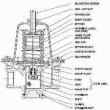
Internal parts of a pressure reducing / water feed valve
- POST a QUESTION or COMMENT about heating boiler pressure reducing valves, water feed valves, check valves: operation and repair
Heating boiler water feeder valve disassembly.
Page to sketch: parts list for a typical B&G pressure reducing valve.
[Click to enlarge any image]
This article series explains the operation and repair of hot water boiler (hydronic heat) pressure reducing valves and types of manual and automatic water feeder valves used on hot water heating boilers, including when and how to add makeup water to a boiler.
InspectAPedia tolerates no conflicts of interest. We have no relationship with advertisers, products, or services discussed at this website.
- Daniel Friedman, Publisher/Editor/Author - See WHO ARE WE?
Take Apart a Hydronic (hot water) Heating Boiler Pressure Reduce Valve
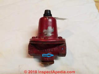 Here we illustrate complete dis-assembly of an older B&G B-8 pressure reducing valve.
We found this valve on a hot water heating system in a Two Harbors Minnesota home built in the 1960s.
This was an original pressure reducer that had served more-or-less for over fifty years.
I say more-or-less because nobody knows just when this valve stopped feeding water to the boiler.
On a heating service call, working with the local heating repair technician, we had observed some loss of water in the heating system.
After draining the boiler to remove pressure so that we could replace air bleeder valves and a bad TP relief valve on the boiler, we turned water back on to the boiler.
Nothing happened: no water entered the boiler.
While the B&B pressure reducer shown here can be cleaned or repaired in the field, the technician declined to do so.
Instead we bought and installed a new pressure reducing valve.
Later back in our Poughkeepsie workshop we decided to dis-assemble the valve completely in order to examine conditions in a 50+ year old B&G pressure regulator.
My first discovery was that the technician was much smarter than I was.
Steps in Complete Disassembly of a B&G Pressure Reducer
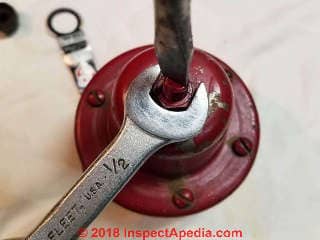
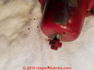
Above: loosening the lock nut on the pressure reducer adjustment screw. To access this screw you may have to remove a plastic cap on the valve top.
Watch out: loosening or even removing this nut will NOT permit dis-assembly of the valve. This adjustment screw is turned clockwise (in) to increase the feed pressure to the boiler, or counter-clockwise (out) to reduce the water feed pressure to the boiler.
Normally the pressure reducing valve is pre-set at the factory to feed water to a boiler when boiler pressure drops below 12 psi
If you need to adjust the pressure of your boiler's pressure reducer ("water feeder") see
WATER PRESSURE SETTING FOR A PRESSURE-REDUCING VALVE OR WATER FEEDER ON A HOT WATER HEATING SYSTEM
Watch out: I do NOT recommend that you try complete dis-assembly of a pressure reducing or water feed valve.
The photos and notes included here are for educational purposes to show novices the internal workings of a typical and normally rock-solid pressure reducer made by B&G. But if you rip apart a valve as I do here you may not get it back together to work safely.
Starting
at PRESSURE REDUCING VALVE (BOILER) CLOG REPAIR I show removing the pressure reducer strainer nut to remove and clean the strainer.
If replacing or cleaning the pressure reducer strainer doesn't get the valve working again I suspect its internal valve is jammed, as I will illustrate.
In that case it's best to repalce the entire valve - and less time and cost in labor and materials.
Below I begin actual dis-assembly of the B&G Pressure Reducer.
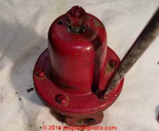
All of the valve body screws are removed and set aside.
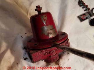
Below, with the body screws removed I am prying the valve upper and lower body halves apart.
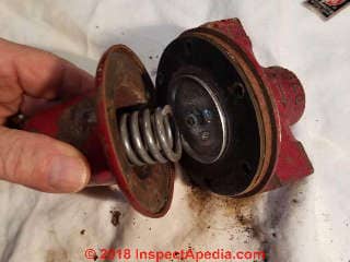
Below I'm pulling the pressure reducer apart.
In the photo left you can see the heavy spring that, adjusted by the screw shown above and apressure plate I'll show next the pressure on the diaphraghm at the valve centr is adjusted.
That diaphraghm in turn will permt the water flow valve assembly (shown later) to open or close.
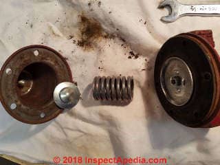
Below from left to right you can see the pressure reducer valve spring cap and inside it the point of the screw that is turned up or down to press on the round pressure plate that in turn presses a spring that in turn presses on a metal plate affixed to the center of the pressure reducer rubber diaphraghm.
Water pressure on the supply side (under the valve, connected to building water piping) wants to press the diaphraghm up to open the valve.
Spring pressure on the upper side of the diaphraghm presses the diaphraghm down to close the valve.
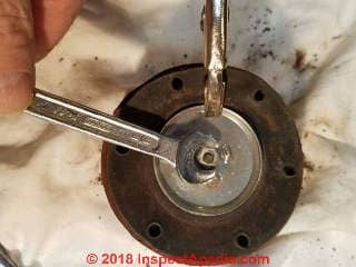
Below: to expose the actual water valve that is operated by the diaphraghm I had to loosen the lock screw shown below and later un-screw the water valve from the valve body (shown later).
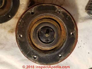
Below, with the pressure plate of the diaphraghm removed we see the centter of the valve and the upper side of the actual water control valve.
Below I've removed the rubber cover to show both the water control valve (center) and the water flow opening in the valve's body.
When the water valve is pushed up by water pressure (against spring pressure), water can pass through the water valve (shown below) and the valve body opening to enter the boiler.
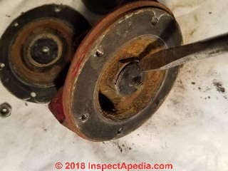
Below my screwdriver points to the actual water flow valve that is controlled by the pressure reducer diaphraghm.
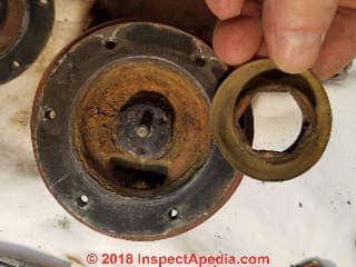
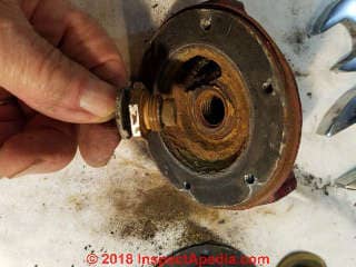
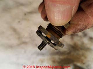
Below, after much fighting, I've managed to un-screw and remove the actual water flow valve of the pressure reducing valvfe.
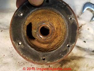
Below: I show the valve main water flow openings in the valve center (controlled by the water valve detailed later) and the oval opening in the side of the valve body.
Below is the pressure reducer water flow valve in its open position.
Above: water can flow under the valve's under-side stopper and through the valve outlet disc on its upper side.
In this position spring pressure is greater than water pressure so water can pass through the valve into the boiler.
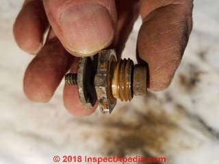
Below I show the pressure reducer's water flow control valve in its "closed" position.
In this position the valve's stopper head on its under-side (right side in the photo) is closed against the valve body screw and its disc has moved upwards against spring pressure. Water pressure is greater than spring pressure in this position.
This valve would not move freely between open and closed when I first dis-assembled it. I had to pry and wiggle to get the parts moving to make these photos.
That would explain why even if we had replaced the clogged strainer on this pressure reducing valve it would still not have worked.
The service tech, in insisting on simply replacing the valve, was dead right.
Pressure Reducer & Flow Control Valve Manuals
- B&G Flo-Control Valves - installation, operation, and service instructions manual [PDF] original source Bell & Gossett, 8200 N. Austin Ave., Morton Grove IL 60053, USA - Tel 847 966-3700 Fax 847 965-8379 . www.bellgossett.com/BG-Literature-Detail.asp?LiteratureID=607
- B&G / ITT Reducing Valves, Instruction Manual V55999: Reducing Valves Installation, Operation, & Service Instructions [PDF] Bell & Gossett Air Separators and other heating system components, Bell & Gossett, 8200 N. Austin Ave., Morton Grove IL 60053, USA - Tel 847 966-3700 Fax 847 965-8379. Original source www.bellgossett.com/literature/files/610.pdf
...
Continue reading at PRESSURE REDUCING VALVES - topic home, or select a topic from the closely-related articles below, or see the complete ARTICLE INDEX.
Or see these
Recommended Articles
- PRESSURE REDUCING VALVES
- MANUAL WATER FEEDER VALVES ON HOT WATER BOILERS
- AUTOMATIC WATER FEEDER VALVES ON HOT WATER BOILERS
- AUTOMATIC HEATING SYSTEM AUTOMATIC WATER FEEDER BUILT-IN BACKFLOW PREVENTER
- IS THE B&G PRESSURE REDUCER AN AUTOMATIC WATER FEED VALVE
- ADD A LOW WATER CUTOFF SAFETY VALVE?
- MAKEUP WATER REQUIREMENTS - HYDRONIC HEAT VERSUS STEAM HEATING BOILERS
- PRESSURE REDUCING VALVE (AUTOMATIC WATER FEEDER) HAS TWO ADDITIONAL FEATURES
- PHOTO GUIDE TO HEATING BOILER PRESSURE REDUCING VALVES
- WATER PRESSURE SETTING FOR A PRESSURE-REDUCING VALVE OR WATER FEEDER ON A HOT WATER HEATING SYSTEM
- AUTOMATIC WATER FEEDERS BUILT-INTO EXPANSION TANKS
- PRESSURE REDUCING VALVE TROUBLESHOOTING, INSPECTION, SERVICE & REPAIR PROCEDURE
- PRESSURE REDUCING VALVE (BOILER) CLOG REPAIR
- PRESSURE REDUCING VALVE DISASSEMBLY
- PRESSURE REDUCING VALVE REPAIR KIT
- PRESSURE REDUCING VALVE WATER FEEDER INSTALLATION
Suggested citation for this web page
PRESSURE REDUCING VALVE DISASSEMBLY at InspectApedia.com - online encyclopedia of building & environmental inspection, testing, diagnosis, repair, & problem prevention advice.
Or see this
INDEX to RELATED ARTICLES: ARTICLE INDEX to HEATING SYSTEMS
Or use the SEARCH BOX found below to Ask a Question or Search InspectApedia
Ask a Question or Search InspectApedia
Try the search box just below, or if you prefer, post a question or comment in the Comments box below and we will respond promptly.
Search the InspectApedia website
Note: appearance of your Comment below may be delayed: if your comment contains an image, photograph, web link, or text that looks to the software as if it might be a web link, your posting will appear after it has been approved by a moderator. Apologies for the delay.
Only one image can be added per comment but you can post as many comments, and therefore images, as you like.
You will not receive a notification when a response to your question has been posted.
Please bookmark this page to make it easy for you to check back for our response.
Comments


IF above you see "Comment Form is loading comments..." then COMMENT BOX - countable.ca / bawkbox.com IS NOT WORKING.
In any case you are welcome to send an email directly to us at InspectApedia.com at editor@inspectApedia.com
We'll reply to you directly. Please help us help you by noting, in your email, the URL of the InspectApedia page where you wanted to comment.
Citations & References
In addition to any citations in the article above, a full list is available on request.
- In addition to citations & references found in this article, see the research citations given at the end of the related articles found at our suggested
CONTINUE READING or RECOMMENDED ARTICLES.
- Carson, Dunlop & Associates Ltd., 120 Carlton Street Suite 407, Toronto ON M5A 4K2. Tel: (416) 964-9415 1-800-268-7070 Email: info@carsondunlop.com. Alan Carson is a past president of ASHI, the American Society of Home Inspectors.
Thanks to Alan Carson and Bob Dunlop, for permission for InspectAPedia to use text excerpts from The HOME REFERENCE BOOK - the Encyclopedia of Homes and to use illustrations from The ILLUSTRATED HOME .
Carson Dunlop Associates provides extensive home inspection education and report writing material. In gratitude we provide links to tsome Carson Dunlop Associates products and services.


