
 Residential Electrical Wiring Code
Example: Centerville IN adoption of US NEC
- POST a QUESTION or COMMENT about electrical service & branch circuit wiring
Electrical wiring code example with additional details based on a city's adoption of the U.S. NEC National Electrical Code.
This article series explains how to estimate the electrical service size, (or "electrical power" or "service amps") at a building by visual examination of the buried service entry cables and other details that are available by simple visual inspection.
InspectAPedia tolerates no conflicts of interest. We have no relationship with advertisers, products, or services discussed at this website.
- Daniel Friedman, Publisher/Editor/Author - See WHO ARE WE?
2019 Electrical Code Chapter 152, Residntial wiring Code
- as adopted by Centerville IN Includes the following sections:
General Provisions
152.01 Definitions
152.02 National Electric Code available for inspection
152.03 Right to refuse service; tampering with electric meters
152.04 Permits required
152.05 Incorporation of certain drawings by reference
Minimum Standards
152.20 Compliance with National Electric Code
152.21 Wiring installation; inspection
152.22 Outlets and switch-points
152.23 Meter sockets
152.24 Clearance requirements
152.25 Breaker boxes, cables and farm pole load centers
152.26 Service entrance conductors
152.27 Installation of service equipment, conductors
152.28 Underground installations
152.29 Grounding
152.30 Service requirements for residences
152.31 Service entrance equipment
152.32 Service distribution panel
152.33 Bonding required for service equipment
152.34 Branch circuit wiring methods
Service Load Calculations
152.45 Service load calculations required
152.46 Standards for residential service load calculations
152.47 Determining number of small appliance branch circuits
152.48 Outlets for branch circuits
152.49 Special purpose outlets
152.50 Calculation of minimum service load
152.51 Calculation of service load for certain size dwellings
152.52 Reducing feeder service neutral
152.53 Calculations based on National Electric Code sections
GENERAL PROVISIONS
§ 152.01 DEFINITIONS.
The words and phrases used in this chapter shall be defined according to the definitions set forth in most current edition of the National Electric Code until the Code is revised. (Prior Code, § 152.01)
§ 152.02 NATIONAL ELECTRIC CODE AVAILABLE FOR INSPECTION.
The most current edition of the National Electric Code and any subsequent revision shall be available to the public for inspection during regular business hours in the office of the town’s Clerk-Treasurer. (Prior Code, § 152.02)
§ 152.03 RIGHT TO REFUSE SERVICE; TAMPERING WITH ELECTRIC METERS.
The Centerville Municipal Electric Utility (CMEU) reserves the right to refuse service to anyone failing to comply with the minimum requirements stated in this chapter or which is deemed to be hazardous to persons or property. No electric meter shall be removed, except at the direction of the CMEU. A customer found tampering with an electric meter shall have his or her electric service discontinued at the discretion of, and after appropriate action by, the Town Council. (Prior Code, § 152.03)
§ 152.04 PERMITS REQUIRED.
Permits are required to be obtained through the Building Commissioner for all new one- and two-family dwelling installations and for all alterations, modifications, deletions or other changes to existing electric service. All commercial applications must be filed with the state’s Administrative Building Council before local permits may be issued. (Prior Code, § 152.04)
§ 152.05 INCORPORATION OF CERTAIN DRAWINGS BY REFERENCE.
The following drawings are hereby incorporated by reference in this chapter as if fully set forth herein. Copies are on file with the Building Commissioner:
(A) Farm pole - center service installation; (
B) Typical 400 amp - farm pole service installation with emergency generation facility;
(C) Service attachment to mast for house with low overhanging roof;
(D) Residential underground service installation;
(E) Typical mobile home meter and service pedestal;
(F) Isolated mobile home service entrance installation; (G) Typical residential meter and service entrance installation; and (H) Temporary service from overhead installation. (
Prior Code, § 152.05)
MINIMUM STANDARDS
§ 152.20 COMPLIANCE WITH NATIONAL ELECTRIC CODE.
All electrical wiring materials, devices and electrical equipment installed in or about residences in the area serviced by the Centerville Municipal Electric Utility shall conform to the standards of the National Board of Fire Underwriters, as now established and set forth in the most current edition of the National Electric Code, unless otherwise covered by this chapter.
(Prior Code, § 152.10)
§ 152.21 WIRING INSTALLATION; INSPECTION.
(A) All wiring shall be neatly and completely installed, except for the fixtures that the inspector may want left open for inspection. All wiring shall be subject to two inspections, a rough-in inspection and a completed inspection.
These inspections shall be conducted by either the Building Commissioner or a designated Town Municipal Electric Utility inspector, in accordance with the most current edition of the National Electric Code.
(B) The minimum size for an access opening for a residence shall be 20 inches by 24 inches; for a commercial building, the minimum size for an access opening shall be 22 inches by 30 inches. (Prior Code, § 152.11)
NEC reference: For protection of electrical wiring, see Articles 300-4, 333-12 and 336-9
Size of wiring to be in accordance with ampacity of conductors, see Tables 310-16 through 310-19
§ 152.22 OUTLETS AND SWITCH-POINTS.
At least six inches of free conductor shall be left at each out-let and switch-point where there is the making up of joints or the connection of fixture devices (NEC 300-14). These outlets and switch- points shall be left open for final inspection. All junction boxes shall be readily accessible for the purpose of inspection. (Prior Code, § 152.12)
§ 152.23 METER SOCKETS.
(A) The meter socket shall be furnished, and its location shall be determined, by the town’s Municipal Electric Utility.
(B) It shall be installed as part of the service entrance by the customer’s electrician.
(C) A drawing is on file and may be obtained from the Building Commissioner. (Prior Code, § 152.13) NEC reference: For other provisions, see Articles 110-12,110-14, 300, 300-32, 324, 336, 370-3 through 370-19, 380, 410, 725-38(a)(2) and 800
§ 152.24 CLEARANCE REQUIREMENTS.
All weatherheads shall be located high enough to maintain the following clearances. All service wires must have a ten-foot ground clearance over lawns, sidewalks and the like or a service mast shall be used. All service wires must have an 18-foot clearance over driveways.
All service wires must have a 27-foot clearance over railroads. Service conductors must have a clearance of 36 inches from windows, doors, porches, fire escapes and the like.
(Prior Code, § 152.14) NEC reference: For other provisions, see Articles 230 and 230-50 Swimming pool and fountain installations, see Article 680
§ 152.25 BREAKER BOXES, CABLES AND FARM POLE LOAD CENTERS.
Farm pole centers shall be of the meter pole type, 120/240 V three-wire single phase entrance cable. In each building where loads may exist, the service drop shall be on separate breakers from the meter pole.
The ampacity of the entrance cable and cable from the load side of the breaks will be calculated in accordance with Tables 310-16 through 310-19 of the most current edition of the National Electric Code or subsequently revised editions.
A drawing of a typical farm pole-load center service installation with throwover facilities for emergency generation 400 A, 120/240 V three-wire single phase system may be obtained from the Building Commissioner when an electric permit is obtained for a service installation.
A drawing of a farm pole-center service installation 120/240 V three-wire single phase is also on file with, and may be obtained from, the Building Commissioner. (Prior Code, § 152.15) §
152.26 SERVICE ENTRANCE CONDUCTORS.
(A) The minimum requirements for service entrance conductors under this chapter shall be the same minimum requirements as set forth in the most current edition of the National Electric Code (NEC), and subsequent revisions.
(B) The conductors from the point where the service drops end, up to the service equipment, are called service-entrance conductors.
Types TW, THW, RHW or any other type conductor suitable for outdoor (wet) locations may be used. They may be separate wires brought into the service-entrance weatherhead through conduit to the meter base or cables made up into a service-entrance cable approved for this purpose.
(C) Service-entrance cables are governed by the National Electric Code as follows.
(1) NEC 230-40(a). Service-entrance conductors shall be insulated.
(a) Exceptions 1, 2 and 3. Bare copper-grounded conductor is acceptable if in a raceway, or direct burial is acceptable where suitable for the soil condition, or in soil when the cable has moisture and fungus-resistant covering.
(b) Exception 4. Aluminum-grounded conductor without individual insulation or covering is acceptable if in a raceway, or direct burial is acceptable when part of the cable assembly which has a moisture and fungus-resistant outer covering and which is approved for the purpose.
(2) NEC 230-41(a). Service-entrance conductors shall have ampacity to carry loads as per NEC Article 220.
(3) NEC 230-41(b), underground conductors.
NEC 230-41(b-1), (b-2). In single-family dwellings with six or more two-wire branch circuits or with an initial computed load of ten kw or more, conductors shall have an ampacity of not less than 100 amperes three-wires.
(4) NEC 230-41(b-3). Not smaller than 60 amperes for other loads.
(a) Exception 1. Not smaller than No. 8 copper or No. 6 aluminum for more than two two- wire branch circuits.
(b) Exception 2. Not smaller than No. 8 copper or No. 6 aluminum if by special permission for loads limited by demand or by source of supply, according to the town’s Municipal Electric Utility.
(c) Exception 3. Not smaller than No. 14 copper or No. 10 aluminum for limited loads of a single-branch circuit, but never smaller than the branch-circuit conductors. (See NEC 220-3b.)
(5) NEC 230-54. A maintight service head is required.
(6) NEC 230-54(c). Service heads shall be located above the service drop conductors; however, where it is impracticable to locate the service head above drops, it may be located not more than 24 inches to one side.
(7) NEC 230-54(e). Service conductors shall be brought out through separately bushed holes in the service heads. (Prior Code, § 152.16)
NEC reference:
For calculation of wire size for allowable ampacities, see Tables 310-16 through 310-19 and Articles 220 and 220-22
Grounding electrode conductor, see Table 250-94
Service entrance conductors, see Articles 230 and 238
Service entrance equipment disconnecting means and overcurrent protection, see Article 230
§ 152.27 INSTALLATION OF SERVICE EQUIPMENT, CONDUCTORS.
(A) Service equipment shall be installed on the first floor or in the basement of the residence.
It shall not be installed in the attic, on the second floor, or in a clothes closet. In every case service conductors shall enter the building as soon as possible and service conductors shall not be in the hollow part of the wall.
Service equipment shall be installed in accordance with National Electric Code (NEC) Article 230.
(B) Branch circuits and feeder calculations as designated in NEC Article 220 shall be used to compute the load requirements of a one- and two- family residence.
It is recommended that where load requirements are large, as in a totally electric home, the calculations shall be discussed with the town’s Municipal Electric Utility (CMEU) and the Building Commissioner to insure adequate service to the customer.
(C) All service equipment mounted outdoors or on unenclosed porches shall be rain-tight. No meter shall be mounted inside of a building. All meter bases shall be mounted approximately five feet six inches above the finished grade.
If the adding of a room or garage will enclose a meter, the customer shall move the service at his or her own expense. The CMEU will in turn relocate the service drop if necessary; however, if this change requires setting an additional pole or the replacement of the service drop the work shall be done at the customer’s expense. (Prior Code, § 152.17)
NEC reference:
For additional provisions, see Articles 230-79C and 230-41(b)(3)
§ 152.28 UNDERGROUND INSTALLATIONS.
(A) National Electric Code (NEC) Table 310-13 identifies acceptable types of underground service entrance cable. Underground feeder and branch circuit cable shall be an approved type UF cable in sizes No. 14 copper, or No. 12 aluminum or copper-clad aluminum through No. 4/0.
(B) Provisions as set forth in NEC Articles 339-1(a) (b), 339-2, 300 through 300-5, and sections 310-13, 240-3 and 310-12(c) concerning installation of underground feeder and branch circuit cable shall be applicable.
(C) In addition to the insulated conductors, the cable shall be permitted to have an approved size of insulated or bare conductor for equipment grounding purposes only. The overall covering shall be flame- retardant, moisture-, fungus- and corrosion-resistant, and suitable for direct burial in the earth.
(D) The underground service is the chosen option of the customer. A weatherproof fused switch or breaker must be installed on the feeder end of the cable before going underground (Rule 32, Utility Company Rules). Underground service cost shall be paid by the customer; however, overhead service cost may be deducted as this is normally furnished by CMEU when the underground cable and fixtures are purchased by CMEU for the customer.
(E) Service-entrance underground installation. The underground service installation is covered by National Electric Code requirements.
(1) Service lateral conductors shall be insulated.
(a) Exceptions A, B and C. Bare copper-grounded conductors are acceptable if in a raceway, or direct burial is acceptable where suitable for soil conditioning, or in any soil when cable has moisture and fungus-resistant covering.
(b) Exception D. Bare aluminum- grounded conductors are acceptable if in a raceway, or direct burial is acceptable if in a cable with moisture and fungus-resistant covering.
(2) Conductors shall have sufficient ampacity to carry the load. Service laterals shall not be smaller than No. 8 copper or No. 6 aluminum, except for limited loads; and not smaller than No. 12 copper or No. 10 aluminum for limited loads.
(3) When the service lateral conductors are installed by the electrician, the installation must conform to NEC 230-48 and 230-49, which refer to the protection of the conductors against damage and the sealing of underground conduits where they enter the house. NEC 230-49 refers to 300-5, which covers all situations relative to underground wiring.
(4) A minimum 200 ampere service entrance installation is required for all underground services (Rule 32, Utility Company Rules). The trench, service conductors and equipment, except the meter base, shall be furnished and maintained by the customer.
(5) A trench depth of 24 inches minimum is required, as in NEC Table 300-5. The bottom of the trench must be free of loose or projecting stones and debris, and backfill shall be sand or screened earth free of stones and sharp objects for the first six inches above the conductor, as explained in NEC Article 300-5(F).
(6) (a) The line conduit shall be two inches minimum, galvanized steel or P.V.C.-approved for the use (Type 80), as explained in NEC 300-5(i).
(b) It shall be securely installed with a threaded collar and nut at the bottom of the meter base to a minimum depth of one foot below ground level, as explained in NEC Table 300-5.
(7) Conductors shall be 2/0 copper or 4/0 Al with insulation suitable for underground installation, as explained in NEC Article 310-13. Conductors shall be installed in the meter base and trench to the base of the service pole by the customer. The customer’s conductors, conduit and weatherhead will be installed on the pole by the town’s Municipal Electric Utility. The customer has the option of purchasing wire and material from the town’s Municipal Electric Utility at cost.
(8) If trenching is done by the customer, it shall be his or her responsibility to call the excavation in at telephone number 962-9090 for the cable locating service. (
Prior Code, § 152.18) §
152.29 GROUNDING.
(A) Grounding shall be to water pipes when available, with a jumper around the water meter. National Electric Code Article 250 will be applicable, with attention directed to 230-79(C), 250-80, 250-81, 250-83(c)-2 and Table 250-94.
(B) The purpose of grounding is safety. Grounding falls into two categories: system grounding and equipment grounding.
(1) SYSTEM GROUNDING is the connecting of the neutral conductor of the wiring system to the earth. An accidental grounding of a current-carrying conductor, will result in a short circuit causing a fuse or a circuit breaker to open, thereby disconnecting the line conductors.
(2) EQUIPMENT GROUNDING, or grounding non-current-carrying parts of the installation, is the grounding of the steel raceway, service equipment and metal enclosures of equipment, which is accomplished by running a wire from the neutral connection in the main service switch and the meter socket to the water piping system on the street side of the meter.
(C) National Electric Code grounding rules are as follows.
(1) NEC 250-81. Where available on the premises, a metal underground water pipe shall always be the grounding electrode.
(2) NEC 250-92(a); NEC 250-50(a), (b). Metal grounding electrode conductor enclosures shall be electrically continuous from the cabinet to the grounding electrode.
(3) NEC 250-92(a). If the metal enclosure is not electrically continuous, it must be bonded at each end to the grounding conductor.
(4) NEC 250-115. A ground clamp approved for the purpose shall be used to connect the grounding electrode conductor to the grounding electrode.
(5) NEC 250-112. Connection should be on the street side of the water meter or bonding required around valves, meter, unions and the like.
(6) Grounding wire. The size of grounding wire is found in NEC Table 250-94. (Prior Code, § 152.19) § 152.30 SERVICE REQUIREMENTS FOR RESIDENCES. For a one-family dwelling, the service disconnecting means shall have a rating of not less than 100 amps, three wire, under either of the following conditions: where the initial computed load is ten kw or more, or where the initial installation consists of six or more two-wire branch circuits. (Prior Code, § 152.20)
NEC reference: For other provisions, see NEC 230-41
§ 152.31 SERVICE ENTRANCE EQUIPMENT.
(A) For the purpose of this section, the following definitions shall apply unless the context clearly indicates or requires a different meaning.
SERVICE. Defined by the National Electric Code as “the conductors and equipment for delivering energy from the electricity supply system to the wiring system of the premises served”.
SERVICE DROP CONDUCTORS. Defined by NEC Article 100 as “the overhead service conductors from the last pole or other aerial support to and including the splices if any, connecting the service entrance conductors at the building or other structure”.
(B) The local power supplier, the town’s Municipal Electric Utility, decides where the electrical service will enter the building and where the meter will be located. The main parts of a complete electrical service installation shall include the service drop, service conductors, meter, service switch, grounding and bonding.
(C) Service drop conductors are furnished and installed by the power supplier, the town’s Municipal Electric Utility. The customer will furnish the service mast riser, weatherhead, service entrance conduit and supporting equipment.
(D) The National Electric Code rules governing the installation of a service drop are as follows.
(1) NEC 230-2 and exceptions. In general, buildings or other premises shall be supplied by only one set of service conductors.
(2) NEC 230-22 and exceptions. Individual conductors of multiconductor cable, when used as a service drop, shall be insulated or covered with thermoplastic, rubber or other similar material; however, grounded conductor may be bare. Open conductors shall be insulated or covered and have ampacity as per NEC Tables 310-17 and 310-19.
(3) NEC 230-24 (a)-Ex. 1. Where voltage between conductors does not exceed 300 and the roof has a slope not less than four inches, 12 inches, clearance may not be less than three feet.
(4) NEC 230-24 (a)-Ex. 2. Service drops 300 volts or less may pass over four feet of overhang if a minimum of 18 inches clearance is maintained over the roof and the conductors are terminated in a through-the-roof raceway or approved support.
(5) NEC 230-24 and 230-26. Porcelain insulators for the service drop conductors shall be at least ten feet above finish grade.
(6) NEC 230-28. The service mast shall have adequate strength or be supported by braces or guys.
(7) NEC 230-28. All raceway fittings shall be approved for the purpose.
(8) NEC 230-43. Service-entrance conductors may be installed as open wiring on insulators; a rigid metal conduit; electrical metallic tubing; service-entrance cables; wireways; busways; auxiliary gutters; a rigid non-metallic conduit; cablebus; or mineral-insulated metal-sheathed cable.
(9) NEC 300-18(a). Raceways are to be installed as a complete system before wires are drawn in.
(10) NEC 230-26. In no case shall the point of attachment to the service drop be less than ten feet above the finished grade. (Prior Code, § 152.21) §
152.32 SERVICE DISTRIBUTION PANEL.
(A) Definition. For the purposes of this section, the following definition shall apply unless the context clearly indicates or requires a different meaning.
BRANCH CIRCUIT. The circuit conductors between the final overcurrent device protecting the circuit and the outlets.
(B) Types of circuits.
APPLIANCE BRANCH CIRCUIT. A circuit that supplies energy to one or more outlets to which kitchen appliances are connected: no lighting fixtures are permitted on this circuit.
GENERAL-PURPOSE BRANCH CIRCUIT. A circuit that supplies a number of outlets for lighting and small appliances.
INDIVIDUAL BRANCH CIRCUIT. A circuit that supplies power to only one utilization equipment, such as a kitchen electric range.
(C) Types of service panels. There are many types of service distribution panels used in residential wiring. However, there are only two types of overcurrent protection: the fuse and the circuit breaker. Circuit breakers must be clearly marked to show whether they are in the open (OFF) or closed (ON) position. Use a 15-ampere breaker for No. 14 AWG wire; a 20 ampere breaker for No. 12 wire; and a 30 ampere breaker for No. 10 wire. Circuit breakers are made in single-pole and double-pole with voltage and current ratings to match the circuit breaker. The distribution panel cabinet must bear the UL, or other approved, testing agencies, label and it must be marked as suitable for service equipment. The National Electric Code requires that only “type S fuses” be used, and are so designed that they cannot be used in any fuse box other than a type S fuse holder or a fuse holder with a type S adapter inserted.
(D) Circuit interrupters or circuit breakers. The ground-fault circuit interrupter (GFCI) circuit breakers or a GFCI receptacle are required in the following areas:
(1) NEC 210-8, in residential occupancies, on all 120-volt single phase, 15-ampere, 20-ampere receptacle outlets outdoors, in garages and in bathrooms;
(2) NEC 210-8, on the construction site, (usually the temporary power pole). See NEC 210-80, and appropriate drawing incorporated by reference under § 152.05 of this chapter and on file with the Building Commissioner;
(3) NEC 680-6, swimming pools: lighting fixtures (wet-niche);
(4) NEC 680-20, underwater lighting fixtures (wet-niche);
(5) NEC 680-31, storable swimming pools;
(6) NEC 680-41(a), supplying fountain equipment;
(7) NEC 680-50, fountains: all power supply connected equipment;
(8) NEC 680-5, swimming pool transformers;
(9) NEC 555-3, marinas and boatyards;
(10) NEC 517-13, health care facilities;
(11) NEC 215-9, feeders; and
(12) NEC 680-22, bonding of all metallic parts. (Prior Code, § 152.22)
§ 152.33 BONDING REQUIRED FOR SERVICE EQUIPMENT.
(A) For the purpose of this section, the following definition shall apply unless the context clearly indicates or requires a different meaning. MAIN BONDING JUMPER. As defined by the National Electric Code, is the connection between the grounded circuit conductor and the equipment grounding conductor at service.
(B) All service equipment must be properly bonded. The purpose of installing bonding bushings and bonding jumpers on service-entrance equipment is to assure a low impedance path to ground should a fault occur on any of the service entrance conductors.
(C) The following National Electric Code regulations are applicable.
(1) NEC § 250-79(a), (b). The main and equipment bonding jumper shall be copper or some other corrosion-resistant metal and attached as per NEC 250-113 and 250-115.
(2) NEC § 250-79(c). The equipment bonding jumper on the supply side of the service and main bonding jumper shall be sized as per Table 250-94, but not less than 12-1/2% of the largest phase conductor. (Prior Code, § 152.23)
§ 152.34 BRANCH CIRCUIT WIRING METHODS.
(A) Insulation; conductor size.
(1) A conductor with insulation capable of withstanding heat will have a higher ampacity rating than a conductor of the same size with a lower insulator temperature rating. National Electric Code Table 310-13 lists the various types of insulation available.
(2) The NEC § 210-19(c) specifies the minimum conductor size permitted in house wiring as 14 A WG.
(B) Cable support. NEC § 336-5 states that “type NM cable must be fastened by staples or straps so designed and installed as not to injure the cable”. The NEC requires a staple or strap be placed every 12 inches from every box or fitting, and four and one- half feet apart on the run between boxes, including vertical and horizontal runs.
(C) Fastening table to box. NEC § 370-7(c) states that “where non-metallic boxes are used, non-metallic-sheathed cable shall extend into the box no less than one-fourth inch through a non-metallic sheathed cable knockout opening”. When used with a single gang box and where the cable is fastened within eight inches of a box measured along the sheath, the cable extends into the box so no less than one-fourth inch, so that securing the cable to the box shall not be required.
(D) Cable protection. When drilling through studs or joists, the NEC requires non-metallic cable be at least one and one-half inches from the outer edge of the wooden member. Where the hole is drilled closer than the one and one-half inches limit, a one-sixteenth- inch steel plate is fastened to the wooden member in front of the cable to protect it. (See NEC 373.) NEC § 300-14 requires at least six inches of free conductor must be left at each outlet and switch point.
(E) Boxes.
(1) Number of conductors in a box. NEC Table 370-6(a) (Metal Boxes) shall apply where no fittings or devices, such as fixture studs, cable clamps, hickeys, switches or receptacles are contained in the box and where no grounding conductors are part of the wiring within the box. Where one or more fixture studs, cable clamps or hickeys are contained in the box, the number of conductors shall be reduced by one less than shown in NEC Table 370-6(a), and an additional deduction of one conductor shall be made for each strap containing one or more devices. A further deduction of one conductor shall be made for one or more grounding conductors entering the box.
(a) A conductor running through the box shall be counted as one conductor, and each conductor originating outside of the box and terminating inside the box shall be counted as one conductor. Conductors, no part of which leave the box, shall not be counted.
(b) The volume of a wiring enclosure (box) shall be the total volume of the assembled sections and, where used, the space provided by plaster rings, domed covers extension rings and the like, that are marked with their volume in cubic inches. (See NEC 370-6 (a)(1).)
(2) Marking boxes. The National Electric Code requires that boxes other than those described in NEC Table 370-6(a) must be “durably and legibly marked”.
(3) Other boxes. NEC § 370-6(b). Boxes 100 cubic inches or less, other than those described in NEC Table 370-6(a), non-metallic boxes and conduit bodies having provisions for more than two conduit entries shall be durably and legibly marked by the manufacturer with their cubic inch capacity. The maximum number of conductors permitted shall be computed using the volume per conductor listed in NEC Table 370-6(b) and the reductions provided for in NEC § 370-6(a)(1).
(4) Installation.
(a) NEC § 300-15. The box shall be installed at each conductor splice connection point, outlet, switch point, junction point or pull point for the connection of metal-clad cable, mineral-insulated metal sheathed cable, type AC cable, non-metallic- sheathed cable, type AC cable, non-metallic-sheathed cable or other cables, at the connection point between the cable system and a raceway system and at each outlet and switch-point for concealed knob and tube wiring.
(b) NEC § 370-10. In non-combustible material boxes, or fitting, the box shall be so installed that the front edge of the box or fitting will not sit back of the finished surface more than one-fourth inch. In combustible material boxes and fittings, the box shall be flush with the finished surface. (Prior Code, § 152.24)
Electrical SERVICE LOAD CALCULATIONS
§ 152.45 SERVICE LOAD CALCULATIONS REQUIRED.
(A) In accordance with NEC § 220-15, if an under-sized electrical service is installed, full capacity operation will reduce the electric power available to appliances. If overloading the service is severe enough it can cause conductor heating, contribute to insulation breakdown, and cause a fire hazard. To avoid overloading the electrical service, especially where electrical space heating equipment is to be installed, service load calculations shall be mandatory.
(B) The electrician applying for the electrical inspection permit shall be responsible for submitting an accurate architectural-electrical plan together with service load calculations. (Prior Code, § 152.30)
§ 152.46 STANDARDS FOR RESIDENTIAL SERVICE LOAD CALCULATIONS.
The National Electric Code is applicable as follows
(A) NEC Table 220-2(b) shows three watts per square foot.
(B) NEC Section 220-16(a) rates the two small appliance circuits at 3,000 watts (1500 watts each circuit).
(C) NEC Table 220-19, Column C, shows the load for two cooking units to be 65% of the sum of the nameplate rating of the two units.
(D) NEC Section 220-16(b) rates the laundry circuit at 1500 watts.
(E) NEC Article 220-2(b) states: “Unit lighting load for dwelling units shall not be less than three watts per square feet (Table 220-2(b))”. To determine the load on a watts per square foot basis, use the outside dimensions of the dwelling. The computed floor area shall not include open porches, garages, or unused or unfinished spaces unless adaptable for future use. Watts per square foot load shall be apportioned evenly among branch circuits, according to their capacities. By using the example in NEC Chapter 9 for general illumination, one 15 ampere, 115-volt branch circuit would be required for every 575 square feet of occupied floor area.
Example:
3 watts per sq. ft. X 575 = 1725 watts ÷ 115 volts = 15 amps.
A calculated load for a total occupied area of 30 ft. X 55 ft. = 1650 sq. ft. X 3 watts per sq. ft. = 4950 watts
(1) Calculating the minimum number of lighting circuits.
(a) The total required amperes is equal to:
Amperes = - watts volts
Amperes = 4950 watts 115 volts = 43.04 Amperes
(b) The minimum number of circuits required for a general lighting load is obtained by dividing the total required amperes by the maximum amperage rating of each circuit.
Example:
43.04 maximum required 15 amp rating = 2.86 or three circuits minimum required
(2) Convenience outlets. NEC Table 220-2(b) states “receptacles other than those of the two small appliance circuits are considered part of general illumination and require no allowance for additional load...”. An electric clock outlet may be installed on the general lighting circuit. (Prior Code, § 152.31)
§ 152.47 DETERMINING NUMBER OF SMALL APPLIANCE BRANCH CIRCUITS.
(A) Kitchen. NEC § 220-3(b). For a small appliance load, including refrigeration equipment in the kitchen pantry, breakfast room, dining room and family room, two or more 20-ampere appliance circuits shall be provided. Such circuits have no other outlets. The outlets in the kitchen shall be supplied by at least two 20-ampere circuits. NEC § 220-16(a) provides that the feeder load for the two small appliance circuits required in NEC § 220-3(b) is to be taken at 3,000 watts or 1,500 watts for each two-wire circuit.
(B) Laundry. At least one additional 20-ampere branch circuit is needed to supply laundry receptacle outlets. No other outlets may be on this circuit according to NEC § 220-3(c). This circuit could be calculated at 1500 watts according to NEC §§ 210-50(c), 210-52-E and Chapter 9 with Example #1. (Prior Code, § 152.32)
§ 152.48 OUTLETS FOR BRANCH CIRCUITS.
(A) Convenience outlets are connected to the general lighting branch circuits with the exception of the receptacles in the kitchen. These outlets are connected to the 20-ampere small appliance circuit. (See NEC Section 210-52.)
(B) The National Electric Code does state general requirements for the location of these outlets. (See NEC § 210-52.)
(1) Receptacles. NEC § 210-58(a) requires that, in dwellings, receptacles must be installed as follows:
(a) In all rooms of general occupancy, no space along a wall is to be more than six feet from a receptacle outlet, measured horizontally;
(b) In any wall space two feet or more in width;
(c) In a kitchen where each counter space is wider than 12 inches;
(d) Insofar as practicable, spaced an equal distance apart;
(e) With at least one wall outlet in the bathroom near the basin (on a GFCI circuit). See NEC §§ 210-25(b) and 210-8(a);
(f) With at least one outlet outdoors (on a GFCI circuit);
(g) With at least one outlet in the basement in addition to the laundry outlet;
(h) With at least one outlet in each attached garage. See NEC § 210-8;
(i) Within six feet of an intended location of an appliance; and
(j) In addition to any receptacles located, or five and one-half feet above, the floor.
(2) Lighting outlets. NEC § 210-26(a), dwelling units, is applicable as follows.
(a) At least one wall switch controlled- lighting outlet must be installed in every habitable room, bathroom, hallway, stairway, attached garage and outdoor entrance.
(b) At least one lighting outlet shall be installed in an attic, underfloor space, utility room and basement area used for storage, or space containing an equipment-requiring service.
(3) Bathrooms. NEC § 210-52 requires at least one receptacle outlet near the basin. Section 210-8(a) states that “all 120 volt, 15 and 20 ampere receptacles installed in the bathroom shall have ground-fault circuit interrupter protection. Underwriters Laboratories require that all GFCI’s be tested monthly”.
(4) Garages. NEC § 210-8 states that “all 120-volt 15-20 ampere receptacles installed in the garage shall have ground-fault circuit interrupter protection”. (See NEC § 210-8(A) exceptions 1 and 2.)
(5) Outside receptacles. An outside receptacle is required to be on ground-fault GFCI and to have a weather-proof cover.
(6) Basement. The basement requires a ceiling light in each storage area. If the basement is finished as a family room, the same requirements shall apply as to a living room area upstairs and receptacle outlets shall be provided for. In accordance with NEC § 210-7, “all receptacles installed on 15 and 20 amp branch circuits must be grounding type receptacles”. (Prior Code, § 152.33)
§ 152.49 SPECIAL PURPOSE OUTLETS.
Regulations as to special purpose outlets are as follows.
(A) Cooking unit. The range receptacle shall be surfaced mounted in such a way as to afford protection to the conductors.
(1) NEC Table 220-19 allows a demand factor for electric ranges, wall-mounted ovens, counter-mounted cooking units and other cooking appliances over 1-3/4 kw rating.
(2) A load of only eight kw (8000 watts) may be used for any range rated at not more than 12 kw (12,000 watts). If the range is rated at over 12 kw, start with eight kw. For each kilowatt or fraction thereof above the 12 kw, add 400 watts (or 5% of 8,000 watts).
(B) Hot water heater. The following National Electric Code sections apply to the load demands on a branch circuit by a water heater.
(1) NEC § 422-14(b) states that “all fixed water heaters having a capacity of 150 gallons or less shall be considered a continuous duty load”.
(2) NEC § 422-5(a) exception 2 states that for a continuous load appliance, “the branch circuit rating shall not be not less than 125% of the marked rating” of the appliance.
(C) Clothes dryer. A separate circuit must be provided for an electric clothes dryer.
(1) NEC § 250-45(C) states “clothes dryers must be grounded”, but may be grounded to the neutral of the circuit wire if the grounded conductor is No. 10 AWG or larger.
(2) NEC § 200-18 requires a circuit with a minimum of 5,000 watts’ capacity or a capacity based on the rating of the dryer, whichever is higher. Dryers are usually installed by using a cord and plug and a receptacle, which must be 30 amperes, three- wire.
(D) Dishwasher. The NEC states that a built-in dishwasher and trash compactor intended for use in a dwelling, if provided with a three-conductor cord terminated with a grounding-type attachment plug, shall be permitted if the cord is three to four feet in length, the receptacle is located to avoid physical damage to the cord and is located in an accessible area in the space occupied by the appliance or adjacent thereto. A split receptacle may be used for both a garbage disposer and a dishwasher when located under or near a sink.
(E) Garbage disposer. The NEC requires running overcurrent protection not to exceed 125% of the full load current rating of the motor.
(1) NEC § 442-8(d) permits a three- conductor cord not less than 18 inches or over 36 inches with a grounding type attached plug to be used; provided, the receptacle is accessible and located so as to avoid physical damage to the flexible cord.
(2) A 20-ampere circuit is sufficient for a 120-volt disposer. (Prior Code, § 152.34) §
152.50 CALCULATION OF MINIMUM SERVICE LOAD.
With the National Electric Code sections and tables, the minimum service load for a dwelling 40 feet by 25 feet, or 1,000 square feet may be calculated as follows.
(A) Step 1, calculate the lighting load requirements.
1000 sq. ft. by three watts per ft. = 3000 watts (two circuits for lighting load)
(B) Step 2, calculate the small appliance circuits code states.
We use two circuits = 3000 watts.
So far in our calculations, we have four circuits and 6000 watts. (
C) Step 3. It is reasonable to believe that not all lights and outlets for the appliance circuits will be in use at the same time, so a demand factor is used to calculate the feeder demand factor. NEC Table 220-11 shows the first 3,000 watts of lighting and appliance circuits shall be computed at 100%. The remainder of the 3,000 watts are to be computed at 35%.
Example:
Steps 1 and 2 showed a total of 6000 watts
First 3000 watts computed at 100% = 3000 watts
Remainder, 3000 watts computed at 35% = 750 watts
The 6000 watts are now reduced to 3750 watts (
D) Step 4, feeder load for the oven and countertop. NEC Table 220-19 Column C shows taking a demand factor of 65% of the sum of the nameplate rating of the two units.
Example:
Oven is rated at 5000 watts
Countertop rated at 6500 watts 11500 watts
Using the demand factor - 65% 65% of 11,500 watts = 7475 watts
The 11,500 watts are now reduced to 7475 watts
(E) Step 5, compute the feeder load.
Lighting and appliance circuits 3750 watts
Countertop and oven 7475 watts
Dishwasher (cannot be reduced) 1500 watts
Garbage disposer unit 750 watts
Exhaust fan 300 watts 13,775 watts
(F) Step 6, compute the feeder size. The utility company has supplied a 115/230-volt overhead service to the house. The total computed feeder load is 13,755 watts.
Example: 13,755 watts - 230 volts = 59.8 amperes
Table 310-16 of the NEC shows that 59.8 amperes require a #6 AWG, Type THW, copper conductor good for 65 amperes. Table 3A, Chapter 9 of the NEC shows that a 1-1/4 inch conduit is required for 3 #6 AWG, Type THW, copper conductors. (Prior Code, § 152.35) §
152.51 CALCULATION OF SERVICE LOAD FOR CERTAIN SIZE DWELLINGS.
(A) This calculation for a 1,500-square-foot dwelling shall be made as follows. General lighting load 1500 square feet by 3 = 4500 watts 4500 - 115 volts = 39.l amperes (3-15 amp circuits) Allowance for two appliance circuits = 3000 watts (2 circuits-20 amps) Laundry circuit NEC 220-3(a) = 1500 watts (l circuit-20 amps) Net total = 9000 watts (B)
(1) Feeder demand factors. First 3000 watts at 100% = 3000 watts Remainder 6000 watts at 35% = 2100 watts Net total = 5100 watts 12 kw range load (NEC Table 220-19) = 8000 watts Net load with range = 13,100 watts Utility installed 115/230 volt three-wire service. (2) Example: 13,100 watts - 230 volts = amperes NEC Section 230-41(b)(2) Net computed load exceeds 10 kw, so service conductors shall be at 100 amperes. (Prior Code, § 152.36)
§ 152.52 REDUCING FEEDER SERVICE NEUTRAL.
(A) Many electricians prefer to reduce the service neutral conductor. However, for most installations and especially for a dwelling equipped with an electric range, electric clothes dryer and electric hot water heater, a neutral conductor one size smaller than the ungrounded conductors is usually more than adequate. It is recommended that the correct neutral size first be determined using the procedure outlined. (
B) NEC Section 220-22 will allow us to reduce the service neutral.
Example:
Use the calculated service load for a 1500 square foot dwelling in § 152.46. Lighting and appliance load 5100 watts. Range load reduced 70% (8000 by 70% = 5600 watts) 10,700 watts 10,700 watts - 230 volts = 46.5 amperes (Prior Code, § 152.37)
§ 152.53 CALCULATIONS BASED ON NATIONAL ELECTRIC CODE SECTIONS.
Calculations based on National Electric Code sections are as follows.
[Click to enlarge any image]

Electrical Code for Underground Feeders (not permitted for SEC wiring)
If you're looking for codes and details about installing underground service entry cables SEC see this separate article at
Excerpting from the 2020 U.S. National Electrical Code (as adopted by Illinois) in 3 Wiring Methods and Materials > 340 Underground Feeder and Branch-Circuit Cable: Type UF,
340.1 Scope
This article covers the use, installation, and construction specifications for underground feeder and branch-circuit cable, Type UF. 340.2
Definition
The definition in this section shall apply within this article and throughout the Code. Underground Feeder and Branch-Circuit Cable, Type UF. A factory assembly of one or more insulated conductors with an integral or an overall covering of nonmetallic material suitable for direct burial in the earth. 3
40.6 Listing Requirements
Type UF cable and associated fittings shall be listed.
340.10 Uses Permitted
Type UF cable shall be permitted as follows:
(1) For use underground, including direct burial in the earth.
(2) As single-conductor cables. Where installed as single-conductor cables, all conductors of the feeder or branch circuit, including the grounded conductor and equipment grounding conductor, if any, shall be installed in accordance with 300.3.
(3) For wiring in wet, dry, or corrosive locations.
(4) Installed as nonmetallic-sheathed cable. Where so installed, the installation and conductor requirements shall comply with Parts II and III of Article 334 and shall be of the multiconductor type.
(5) As single-conductor cables as the nonheating leads for heating cables as provided in 424.43.
(6) Supported by cable trays. Type UF cable supported by cable trays shall be of the multiconductor type. Informational Note: See 310.14(A)(3) for temperature limitation of conductors.
340.12 Uses Not Permitted
Type UF cable shall not be used as follows:
(1) As service-entrance cable Watch out: this means not for SEC's - Ed.
(2) In commercial garages
(3) In theaters and similar locations
(4) In motion picture studios
(5) In storage battery rooms
(6) In hoistways or on elevators or escalators I
(7) In hazardous (classified) locations, except as specifically permitted by other articles in this Code
(8) Embedded in poured cement, concrete, or aggregate, except where embedded in plaster as nonheating leads where permitted in 424.43
(9) Where exposed to direct rays of the sun, unless identified as sunlight resistant Informational Note: The sunlight-resistant marking on the jacket does not apply to the individual conductors.
(10) Where subject to physical damage As overhead cable, except where installed as messenger-supported wiring in accordance with Part II of Article 396
340.24 Bending Radius [for UF cable]
Bends in Type UF cable shall be so made that the cable is not damaged. The radius of the curve of the inner edge of any bend shall not be less than five times the diameter of the cable.
340.80 Ampacity T
he ampacity of Type UF cable shall be that of 60°C (140°F) conductors in accordance with 310.14.
340.104 Conductors
The conductors shall be sizes 14 AWG copper or 12 AWG aluminum or copper-clad aluminum through 4/0 AWG.
340.108 Equipment Grounding Conductor
In addition to the insulated conductors, the cable shall be permitted to have an insulated or bare equipment grounding conductor.
340.112 Insulation
The conductors of Type UF shall be one of the moisture-resistant types listed in Table 310.4(A) that is suitable for branch-circuit wiring or one that is identified for such use. Where installed as a substitute wiring method for NM cable, the conductor insulation shall be rated 90°C (194°F).
340.116 Sheath
The overall covering shall be flame retardant; moisture, fungus, and corrosion resistant; and suitable for direct burial in the earth.
Electrical Code Resources & Research
- ELECTRICAL CODE Chapter 3, WIRING METHODS and MATERIALS [PDF] as adopted by the U.S. state of Minnesota, that you can see in a for-pay copy of the whole US National Electrical Code - available from NFPA at nfpa.org/product/nfpa-70-code ($153.00 U.S.),
or where adopted by your state or city government, as local law provided at no cost by up.codes.com at up.codes/viewer/minnesota/nfpa-70-2023/chapter/3/wiring-methods-and-materials#3 - as retrieved 2023/11/24 - example from the Minnesota electrical code. - "Evaluating Wiring in Older Minnesota Homes," Agricultural Extension Service, University of Minnesota, St. Paul, Minnesota 55108.
- "Simplified Electrical Wiring," Sears, Roebuck and Co., 15705 (F5428) Rev. 4-77 1977 [Lots of sketches of older-type service panels.]
- "How to plan and install electric wiring for homes, farms, garages, shops," Montgomery Ward Co., 83-850.
- "Simplified Electrical Wiring," Sears, Roebuck and Co., 15705 (F5428) Rev. 4-77 1977 [Lots of sketches of older-type service panels.]
...
Reader Comments, Questions & Answers About The Article Above
Below you will find questions and answers previously posted on this page at its page bottom reader comment box.
Reader Q&A - also see RECOMMENDED ARTICLES & FAQs
On 2022-04-18 by Inspectapedia Com Moderator
@John,
SE CABLE & WIRE SIZES FOR LONG RUNS - SEE THIS ARTICLE for wire size for long runs
On 2022-04-17 by John
Have a garage that’s 900 feet away from power meter. What size underground wire do I need to run or 200 amp service?
On 2022-02-17 by Inspectapedia Com Moderator - Plastic High Heat (PHH) electrical wire temps and ampacity
@David,
As RHH refers to "Rubber High Heat" my guess would be that PHH on electrical wire insulation refers to Plastic High Heat electrical wire.
See our "Table of Wire Types vs. Temperature Ratings Reflected in the Wire Ampacity Chart Above"
found in
https://inspectapedia.com/electric/Electrical_SEC_Sizes_Amps.php
SE CABLE & BRANCH CIRCUIT WIRE SIZES vs AMPS has additional details on wire sizing. (Live link at the Recommended Articles list)
No surprise that the neutral or ground conductors in some electrical wire products may be a smaller wire gauge than the current carrying conductors.
On 2022-02-17 by David
My house was built in 1976. The neutral conductor is made by Philips and is labelled TWH 3. The two hot wires between the meter base and panel are labelled as PHH 1. I have not been able to find specs or ampacity numbers for this wire. Is this an earlier vintage of RHH 1 ?
On 2022-01-20 by Inspectapedia Com Moderator
@Randall,
UF is wire rated for use as an underground feeder. Wire sizes are given above on this page. Please take a look and let me know if any of that is unclear.
On 2022-01-20 by Randall
What size and type of underground cable do I need for a 100 amp sub panel box 50 ft away from main box?
On 2021-09-16 by inspectapedia.com.moderator - what size underground conduit do I need?
@Ned,
On the page above please see the conduit sizing chart given in
Table 2. Electrical Service Conductor Cable Sizes & Amps Ratings for Service Conductors in Conduit
On 2021-09-15 by Ned
What size underground conduit do I need for 100 A sub panel
On 2021-06-05 by mak.church (mod)
@Tom,
See this article for wire size for long runs:
ELECTRICAL SERVICE ENTRY CABLE SIZES FOR LONG WIRE RUNS
On 2021-06-05 by Tom
200 amp service 135 feet length what size teck cable would I need
On 2021-05-13 by danjoefriedman (mod)
@Bill,
At the WIRE SIZE & AMPACITY TABLES
You'll see #8 copper wire is rated for 40 Amps
As you'll see in the articles in this series you'll see some voltage drop at longer runs.
Also it's always safer to fuse at a lower amperage such as 30 amps on that wire.
On 2021-05-13 by Bill
I have underground 100 feet to garage. In panel is two 6g wire and two 8g wire (copper) If I use the 8 gauge for power and 6g for neutral what size breaker should I use
On 2021-04-09 by danjoefriedman (mod)
@Thomas Hocker, take a look at
SE CABLE SIZES FOR LONG WIRE RUNS
On 2021-04-09 by Thomas Hocker
I need to run 775ft from meter pole to 100 amp box in a cabin. what size and kind of direct bury cable should I use? I know there will be a voltage drop its OK.
On 2021-01-27 - by (mod) - isn't there an app that just tells me what wire I need and how to hook it up?
Don you're quite right, and there may already be such electrical design apps, though I suspect designers will be darn scared about pretending they can guide you safely through electrical wiring when there are many safety details that would be apparent to a licensed electrician but may not be apparent thus not mentioned nor considered by a normal person who's not already trained in the field.
Meanwhile this article series does take a stab at giving general wiring guidelines with simple tables: amps, distance, cable sizes, etc. Please take a look.
On 2021-01-26 by Don
In this day and age, can't someone build an app where you start with a specific subpanel, plug into the app what breakers you intend to install (how many 240, how many 120, what amps for each breaker) and then what distance it is to the main panel and it tells you what wire size you need, how many amps on the main panel disconnect breaker, what underground conduit as applicable etc.?
Seems like the rules ought to be known well enough to get the computers in our life to figure out the hard stuff. Example, I'm building a shop 100 feet from the main panel and intend on having a 240v split AC requiring a 20 amp breaker.
The rest of the sub panel will be 120v normal loads of outlets and lights of about 6 breakers 15 amps each. Do I need to size my feeder wire for 100 amps of 120V or am I sizing for 100' of 240 V 50 amps? I mean each hot leg isn't going to see the full panel load? Be so simple to plug the components into an app and it tell me what the wire requirements would be.
On 2020-10-05 by (mod) - what size & type of electrical cable do i need
SE CABLE & WIRE SIZE TABLES vs AMPS gives cable sizes
do let me know if that's unclear
Thanks Dave
On 2020-10-05 by dave
what size & type cable do i need from load side of meter socket to 100 amp service panel going underground in conduit about 25 feet
On 2020-10-01 - by (mod) -
Walter
Just above on this page please see the live link to the following article
SE CABLE SIZES FOR LONG WIRE RUNS - SEE THIS ARTICLE for wire size for long runs
On 2020-10-01 by Walter
what cable do I need for a 400 amp service 650 ft run and what transformer
On 2020-08-26 y Mike Lange
I am looking for underground wire size needed to run 1200 feet .. I would like a 30 amp 240 volt service
On 2020-08-20 by frank
what size underground wire do I use for 200 amp service for generator that is 200 ft away from the service meter?
On 2020-07-05 - by (mod) - translate: CSA USEB90 2CDR AWG4/0 1 CDR AWG1
Thanks, Mike, that's a helpful question.
Translating the markings & letters on your electrical wire: CSA USEB90 2CDR AWG4/0 1 CDR AWG1 is broken down and explained as follows:
CSA = Canadian Standards Association
USEB90 = USEB-90 Underground Service Entrance Cable consists of two compact aluminum conductors individually insulated with RW90 XLPE insulation, laid in parallel, with a helical plain copper wire serving and an overall PVC jacket covering. The copper wire serving is the neutral. The product meets the USEB-90 cable requirements of CSA.
So we know your wire is rated for underground use and from its size, it's intended to serve as an underground service entry cable.
For completeness I explain that OTHER electrical wires designated as designed for underground use will be marked "UF" for "Underground Feeder" - a non-metallic cable that can be used in wet locations or in un-protected locations such as by burying the wire directly in the ground (without a protective conduit). The usual color for UF cable is gray. Where used above ground the cable should be marked UF_B (sunlight resistant).
2CDR = 2 conductors
AWG4/0 = wire gauge or size is 4/0 (for aluminum wire that's suitable for 200A)
1 CDR = 1 conductor
AGW1 = wire gauge 1
So we have two 4/0 conductors (those will be the current carrying wires) and 1 AWG-1 conductor (that'll be the neutral conductor - or grounded conductor and so is a smaller size)
For a nice succinct summary of the properties of USEB-90 or USEB90 electrical cable take a look at General Cable's
PowrServ® XL Underground Secondary Cable Type USEB-90 600 V, Aluminum Conductor, XLPE Insulation, Overall PVC Jacket, CSA Listed [PDF] retrieved 2020/07/05 original source: www.stabiloy.com/NR/rdonlyres/F06452BB-E816-4B70-ABE0-6E4B5E8317EA/0/GCCDN_pg67_PwrServ_USEB_90.pdf or contact General Cable at https://www.generalcable.com/ Telephone: +1.859.572.8000
Available at InspectApedia.com
Question: What do the letters mean on wire: CSA USEB90 2CDR AWG4/0 1 CDR AWG1
2020/07/05 mike said:
What do the letter mean on wire CSA USEB90 2CDR AWG4/0 1 CDR AWG1
Moderator reply: Guidelines for USEB90 Feeder Cable
Thanks, Mike, that's a helpful question.
Translating the markings & letters on your electrical wire: CSA USEB90 2CDR AWG4/0 1 CDR AWG1 is broken down and explained as follows:
- CSA = Canadian Standards Association
- USEB90 = USEB-90 Underground Service Entrance Cable consists of two compact aluminum conductors individually insulated with RW90 XLPE insulation, laid in parallel, with a helical plain copper wire serving and an overall PVC jacket covering. The copper wire serving is the neutral. The product meets the USEB-90 cable requirements of CSA.
So we know your wire is rated for underground use and from its size, it's intended to serve as an underground service entry cable.
For completeness I explain that OTHER electrical wires designated as designed for underground use will be marked "UF" for "Underground Feeder" - a non-metallic cable that can be used in wet locations or in un-protected locations such as by burying the wire directly in the ground (without a protective conduit). The usual color for UF cable is gray. Where used above ground the cable should be marked UF_B (sunlight resistant).
- 2CDR = 2 conductors
- AWG4/0 = wire gauge or size is 4/0 (for aluminum wire that's suitable for 200A)
- 1 CDR = 1 conductor
- AWG1 = wire gauge 1
where
- AWG = American Wire Gauge (AWG) also referred to as the Brown & Sharpe wire gauge. This is a standard method of describing wire sizes or "gauges" that has been in use in North American since 1857.
AWG is further defined and used in
ASTM Standard B 258, Standard Specification for Standard Nominal Diameters and Cross-Sectional Areas of AWG Sizes of Solid Round Wires Used as Electrical Conductors, available from ASTM or astm.org
So putting together all of those wire markings into a prose description, we have two 4/0 conductors (those will be the current carrying wires) and 1 AWG-1 conductor (that'll be the neutral conductor - or grounded conductor and so is a smaller size)
Guidelines for using USEB-90 Underground Feeder Electrical Cable
For a nice succinct summary of the properties of USEB-90 or USEB90 electrical cable take a look at General Cable's
- PowrServ® XL Underground Secondary Cable Type USEB-90 600 V, Aluminum Conductor, XLPE Insulation, Overall PVC Jacket, CSA Listed [PDF] retrieved 2020/07/05 original source: www.stabiloy.com/NR/rdonlyres/F06452BB-E816-4B70-ABE0-6E4B5E8317EA/0/GCCDN_pg67_PwrServ_USEB_90.pdf or contact General Cable at https://www.generalcable.com/ Telephone: +1.859.572.8000
About using USEB-90 cable, and assuming you're in Canada, you might want to see this Canadian electrical code on service entry wiring - a resource provided by the Alberta government:
- CANADIAN ELECTRICAL CODE - SUBJECT: Section 6 – SERVICES & SERVICE EQUIPMENT [PDF] retrieved 2020/07/05, original source: open.alberta.ca/dataset/7887ccca-d84e-4156-8e32-8f3ebd3ed66d/resource/dcc203d3-f30c-4d09-aaec-eef61285222a/download/452-cec-6-rev5.pdf
On 2020-07-02 - by (mod) - what aluminum wire size and type do I need for a 200A service entry of 150 ft in run?
 My goodness, Billy, I've never been mistaken for a computer-bot. Probably a bot would not make spelling errors when trying to respond when only a smartphone was at hand. Thank you for the feedback.
I'm back at the lab and have access to a keyboard for a more-detailed reply to your electrical service UF wire size question.
I also hope you'll help me avoid re-creating "off the cuff" information that we've got more thoroughly stated and organized in the article(s) to which I refer you.
[Click to enlarge any image]
At the page I recommended where we have a detailed table of SEC size vs amps for both aluminum and copper wires,
the SEC CABLE SIZE table in
SE CABLE & WIRE SIZE TABLES vs AMPS you'll see the data that I excerpted in my earlier reply to you. There is not a single "right" answer to your wire size question without a little more information.
In that more-thorough data, we see that choosing an electrical service wire size bears considering not only ampacity but also run length (as you know) and temperature rating of the wire.
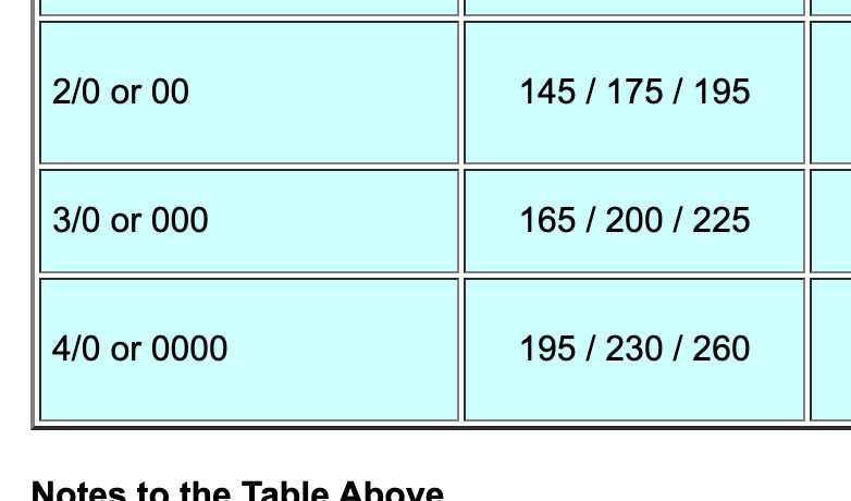
For example the table notes that the rated ampacity for 2/0 or 00 depends:
Conductor Rating Temperature of 60 / 75 / 90 °C permits an amperage of 145 / 175 / 195 respectively for 2/0 - 00 COPPER
while for an ALUMINUM SEC wire the ratings were 115 / 135 / 150 Amps at those temperature ratings.
That's why you're going to find that not 2/0 wire (as you offered) bur rather 4/0 will be where you start for Aluminum SEC cabling if your electrical service size is 200 Amps.
Keep in mind that manufacturers may produce and certify aluminum wire - and mark it right on the wire - for ampacities different than the standard tables that we excerpted from the US National Electrical Code.
Please NOTICE that the manufacturer's remarks that I will site in the next posting are the same as in our table that I recommended, that's 4/0 Aluminum for a 200A service, and that's BEFORE going to a larger size that might be required for longer runs.
Thank you for the discussion - getting SEC wire size right is critical for safety and so your question can help other readers. Below: data for COPPER SEC wire as an example.
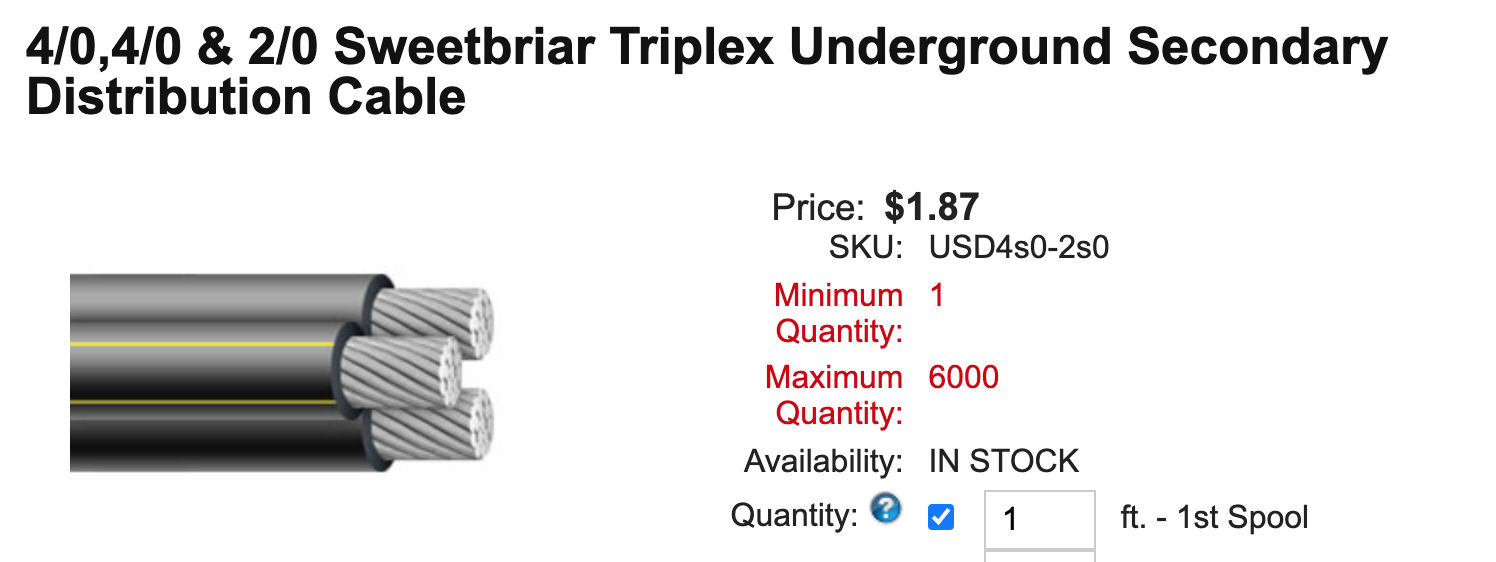 From a retail site example courtesy of Wire & Cable, illustrated here for underground feeder electrical service wiring, we have this specification:
Description:
Underground Secondary Distribution Cables are twisted assemblies of alloy 1350 aluminum conductors insulated with cross-linked polyethylene. THey are used in various underground applications in secondary distribution circuits.
Conductor:
Compressed Class B compressed stranded, 1350 series aluminum alloy.
Insulation:
Black cross-linked polyethylene (XLPE)
Assembly:
Phase conductors and neutral conductors are cabled together to form a twisted assembly.
Applicable Standards:
- UL 854: Service Entrance Cables
- ICEA S-105-692 Standard for 600 Volt Single Layer Thermoset Insulated Utility Underground Distribution Cables
Specifications*:
Phase Conductor Size: 4/0
Phase Conductor Insulation Thickness: 0.080 inches
Neutral Conductor Size: 2/0
Neutral Conductor Insulation Thickness: 0.080 inches
Outside Diameter: 1.38 inches
AC Resistance @ 75°C: 0.101
AC Resistance @ 90°C: 0.105
Inductive Resistance @ 60 Hz: 0.0265
Allowable Ampacity-Direct Burial: 301 Amps at 90°C
Allowable Ampacity-In-Duct: 240 Amps at 90°C
*Data provided on this page is subject to change based on different manufacturers variances.
A you found the wire markings a bit confusing - as do I - that same article translates - for example:
90°C rated wire is marked RHH, RHW-2, XHHW, XHHW-2, XHH, THHW, THWN-2, THW-2, THHN, USE-2
And that same page that I urge you to check out, includes a section titled
"Increase in Electrical Wire Size for Long Distance Wire Runs"
There you'll find a "distance" table that shows how to increase the wire size depending on run length and wire material - copper vs aluminum.
A 200A aluminum SEC running 150 ft needs 600 kcmil wire
If you want more detail, Detailed tables of copper or aluminum SEC cable sizes for long runs and where we give sizes for both single phase and three phase power are at
SE CABLE & WIRE SIZES FOR LONG RUNS
How to Translate the Electrical Wire Markings on NMC Cable
Where we see wire markings like XHHW, we need the decoder that I give just below, organized alphabetically rather than by the order in which letters usually appear on the wire jacket.
- 12/2 = 12-gauge, 2 conductors
- 14/2 = 14-gauge, 2 conductors, etc.
- 14/2 wG = 14-gauge, 2 conductors with ground, etc.
- 600 V = maximum voltage rating for typical residential NM electrical cable
- AL = aluminum conductor
- CU = copper conductor
- H = heat resistant insulation to 167°F.
- HH = high-heat resistant insulation to 194°F.
- N = Nylon-coated wire insulation, resistant to damage by exposure to petroleum chemicals, oil, gasoline, wire may be marked "NYLON"
- NM = non-metallic insulated wire or cable
- NM-B = non-metallic type B electrical cable, has greater heat resistance than straight NM cable.
- Sunlight Resistant - may be marked on such cables that resist damage from sunlight or UV (ultra-violet light)
- T = fire-resistant wire, made using a fire-resistant insulating material
- UF = Underground Feeder - rated for underground use or in wet locations.
- W = Wet-location use wire: approved for damp or wet locations, this wire is also OK to use in dry locations.
- X = flame-resistant wire insulation, made of a flame-retardant polymer
See details in
- Australia, IDENTIFYING WIRE and CABLE [PDF] retrieved 2020/07/05 original source: https://www.casa.gov.au/file/152106/download?token=oG0KQKBG
- UL: WIRE and CABLE MARKING and APPLICATION GUIDE [PDF] (2016), UL, Underwriters Laboratory, retrieved 2020/07/05 original source: https://legacy-uploads.ul.com/wp-content/uploads/2014/04/WC_MG.pdf
Finally:
Of course you want to follow the advice of your electrical power company and your onsite electrician who can see the actual site conditions and requirements - something that I, a mere semi-bot - cannot do from mere e-text sent via internet to our office here on the other side of the US Wall.
Your local electrical inspector is the final legal authority on what's permitted and acceptable for your installation.
On 2020-07-02 by BILLY M.
Sorry if I'm being dense but that table is not consistent with what I've been told by local professionals or the reps from the power company. Are you a real person or a computer bot? Canned answers are not what I'm looking for.
On 2020-07-02 - by (mod) - Billy was told to use 2/0 Aluminum wire for a 200A underground service entry cable
Billy
Check the SEC CABLE SIZE table in
SE CABLE & WIRE SIZE TABLES vs AMPS
For 200A and 150 ft, and select a UF or Underground Feeder rated cable type. That's more critical than the number of strands.
You'll see that if you're using 2/0 wire for 200A you're almost certainly using copper, not aluminum.
An aluminum SEC for 200 A is typically 4/0 and underground will be labeled UF for "underground Feeder"
On 2020-07-02 by BILLY M.
I need to install underground service entrance cable from the power company's pole to the 200 amp service entrance panel.on my house
The distance is roughly 150 feet. I'm told that 2/0 aluminum wire is appropriate for this connection.
However I see there are a number of different types of 2/0 aluminum wire such as SER and SEU, as well as various number of strands within each type...e.g. 2-strand, 2-strand with ground, 3-strand, etc. Exactly what type of wire should I be using for this job? .
On 2020-06-12 by mike
i am running 500 ft underground cable and powering a 80 amp breaker
On 2020-03- by (mod) - adjust underground SEC wire size for longer runs
Mo
Assuming you're using the properly-sized conduit and SEC cabling, the answer is no. Be sure to see the wire size requirements discussed
at SE CABLE & WIRE SIZES FOR LONG RUNS for wire size for long runs - live link is given above on this page
On 2020-03-01 by Mo
I plan to put underground, in conduit, the power supply to my house. The distance is about 80 feet. Do I need to use larger than normally recommended wire to compensate for heat captured in the conduit? Thanx.
On 2019-09-10 by Tim
I want to install 200 amp direct burial wire to my barn that is 400 feet from the meter then in the future I would like to take the service from the barn to another barn that is 600 ft from the first barn . I want to do this in two steps because of cost . What size wire should I use for the first 400 ft in direct burial?
On 2019-08-30 - by (mod) -
Rush
I'm not sure what question you are asking; but in most countries the wire from the utility company's pole to the service connection at the building at a masthead is the responsibility of and is installed by the electric company and is sized by them.
In some locations, particularly where long lines must be run from the utility company's power line across one or more poles across private property to a building, the property owner is responsible for installing the required poles; or service wiring may run underground.
On 2019-08-30 by Rushik
Pole to sarvish cable
On 2019-08-09 - by (mod) -
Greg
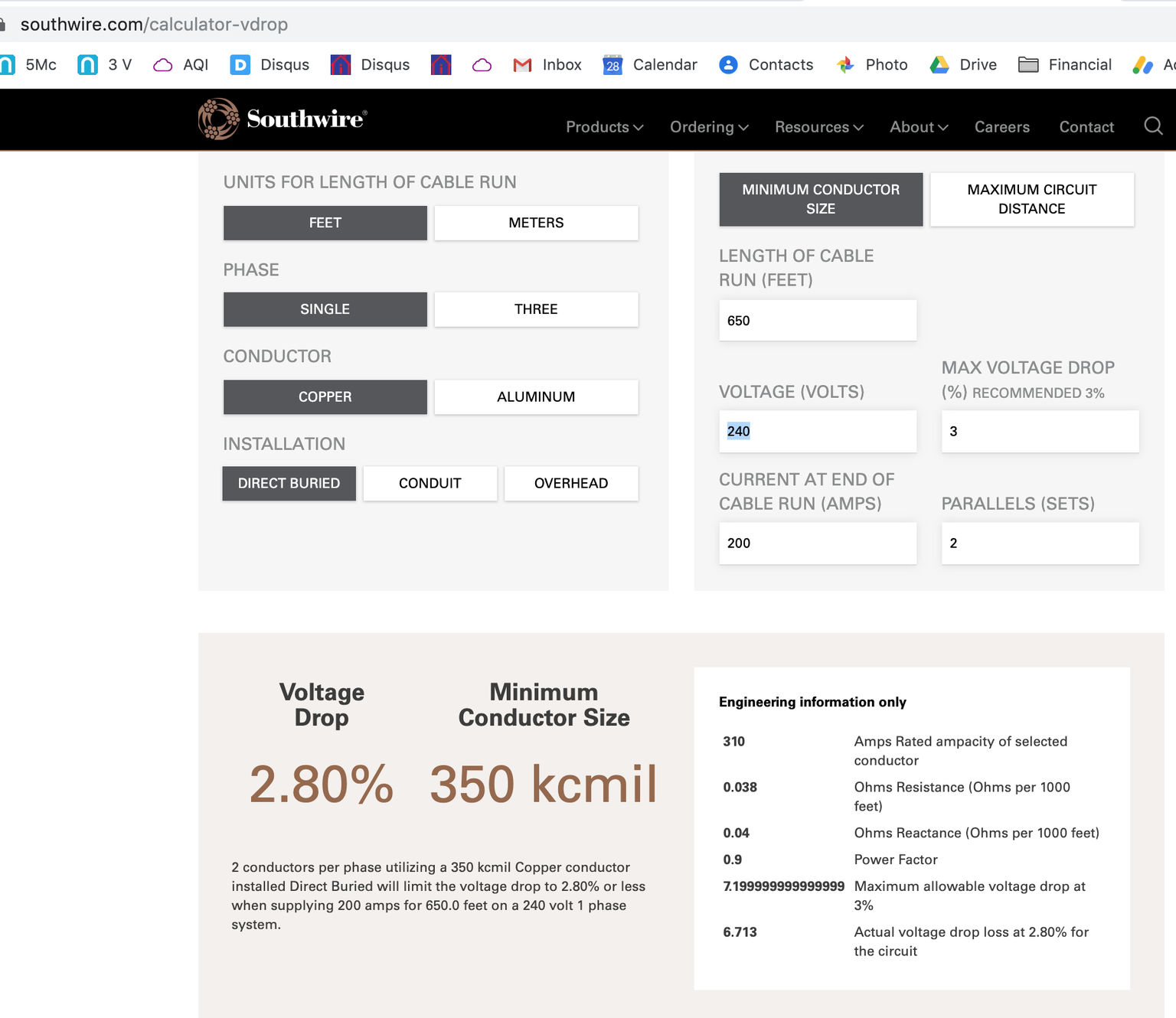
Using the online calculator itself cited at the article I'll cite just below to support a 200A load at the end of the run
you'd see an acceptable (under 3%) voltage drop of 2.80% with 350 kcmil wire
PROVIDED you're running 2 parallel sets of 240VAC cables
you'll find the longest runs we've documented along with wire sizes at
SE CABLE & WIRE SIZES FOR LONG RUNS for help with wire sizing.
On 2019-08-08 by greg
I have a 650' run from the service pole and I'm not sure with the voltage drop what size wire is needed for a 200 amp service.
...
Continue reading at SE CABLE & BRANCH CIRCUIT WIRE SIZES vs AMPS for more wire size guidelines, or select a topic from the closely-related articles below, or see the complete ARTICLE INDEX.
Or see these
Recommended Articles
- AMPS VOLTS DETERMINATION - home
- ELECTRICAL INSPECTOR SAFETY PROCEDURES
- RESIDENTIAL ELECTRICAL WIRING CODE (Eg)
- SERVICE ENTRY WIRING & AMPACITY - home
- ELECTRICAL SERVICE ENTRY DAMAGE
- SE CABLE & BRANCH CIRCUIT WIRE SIZES vs AMPS
- SE CABLE & WIRE SIZES FOR LONG RUNS - SEE THIS ARTICLE for wire size for long runs
- SERVICE AMPACITY
- SERVICE DROP
- SERVICE GROUNDING DEFECTS
- UNDERGROUND SERVICE LATERALS
- SIZE of WIRE REQUIRED for ELECTRICAL RECEPTACLES
Suggested citation for this web page
RESIDENTIAL ELECTRICAL WIRING CODE (Eg) at InspectApedia.com - online encyclopedia of building & environmental inspection, testing, diagnosis, repair, & problem prevention advice.
Or see this
INDEX to RELATED ARTICLES: ARTICLE INDEX to ELECTRICAL INSPECTION & TESTING
Or use the SEARCH BOX found below to Ask a Question or Search InspectApedia
Ask a Question or Search InspectApedia
Share this article:Questions & answers or comments about buried or underground electrical service entry cabling or wiring.
Try the search box just below, or if you prefer, post a question or comment in the Comments box below and we will respond promptly.
Search the InspectApedia website
Note: appearance of your Comment below may be delayed: if your comment contains an image, photograph, web link, or text that looks to the software as if it might be a web link, your posting will appear after it has been approved by a moderator. Apologies for the delay.
Only one image can be added per comment but you can post as many comments, and therefore images, as you like.
You will not receive a notification when a response to your question has been posted.
Please bookmark this page to make it easy for you to check back for our response.
IF above you see "Comment Form is loading comments..." then COMMENT BOX - countable.ca / bawkbox.com IS NOT WORKING.
In any case you are welcome to send an email directly to us at InspectApedia.com at editor@inspectApedia.com
We'll reply to you directly. Please help us help you by noting, in your email, the URL of the InspectApedia page where you wanted to comment.
Citations & References
In addition to any citations in the article above, a full list is available on request.
- The Original Authors: Alan Carson is an ASHI Member, national home inspection educator, author and building failures researcher in Toronto, Ontario. Daniel Friedman, an original author of this article and the editor and producer of InspectAPedia where this article now appears is an ASHI Member, first ASHI Technical Committee chairman, editor and publisher of the ASHI Technical Journal, licensed home inspector, educator, and building failures researcher in Poughkeepsie, NY. Robert Klewitz is a licensed professional engineer, a professional home inspector, an ASHI Member, and has served on the ASHI Technical Committee as well as in other ASHI activities. His practice is in Issaquah, WA.
- ASHI Technical Journal, Vol. 2. No. 1, January 1992, "Determining Service Ampacity," Dan Friedman and Alan Carson, and the
- ASHI Technical Journal, Vol. 3. No. 1, Spring, 1993, "Determining Service Ampacity - Another Consideration," Robert L. Klewitz, P.E., with subsequent updates and additions to the original text ongoing to 2/19/2006. Reprints of the originals and reprints of the Journal are available from ASHI, the American Society of Home Inspectors www.ashi.com.
- Mark Cramer Inspection Services Mark Cramer, Tampa Florida, Mr. Cramer is a past president of ASHI, the American Society of Home Inspectors and is a Florida home inspector and home inspection educator. Contact Mark Cramer at: 727-595-4211 mark@BestTampaInspector.com 11/06
- Douglas Hansen, Robert Stead. Mark Cramer. Photographs: Daniel Friedman.
- N. Srinivasan, MSEE, is a senior member of IEEE with 30 years experience in the electrical industry. Mr. Srinivasan is in Vienna VA.
- Louis P. Babin generously contributed technical editing about the effects of doubling ampacity in an electrical circuit (September 2007)
- "Electrical System Inspection Basics," Richard C. Wolcott, ASHI 8th Annual Education Conference, Boston 1985.
- "Home Wiring Inspection," Roswell W. Ard, Rodale's New Shelter, July/August, 1985 p. 35-40.
- "Basic Housing Inspection," US DHEW, S352.75 U48, p.144, out of print, but is available in most state libraries.
- In addition to citations & references found in this article, see the research citations given at the end of the related articles found at our suggested
CONTINUE READING or RECOMMENDED ARTICLES.
- Carson, Dunlop & Associates Ltd., 120 Carlton Street Suite 407, Toronto ON M5A 4K2. Tel: (416) 964-9415 1-800-268-7070 Email: info@carsondunlop.com. Alan Carson is a past president of ASHI, the American Society of Home Inspectors.
Thanks to Alan Carson and Bob Dunlop, for permission for InspectAPedia to use text excerpts from The HOME REFERENCE BOOK - the Encyclopedia of Homes and to use illustrations from The ILLUSTRATED HOME .
Carson Dunlop Associates provides extensive home inspection education and report writing material. In gratitude we provide links to tsome Carson Dunlop Associates products and services.
 |
HOME | ABOUT | ASK a QUESTION | CONTACT | CONTENT USE POLICY | DESCRIPTION | POLICIES | PRIVACY | |
| © 2026 - 1985 Publisher InspectApedia.com - Daniel Friedman | |||||||||