
InspectAPedia® FREE Encyclopedia of Building & Environmental Construction, Diagnosis, Maintenance & Repair |
Question? Just ask us! InspectAPedia
|
 How Electricity Works: Electricity Basics for Homeowners
- POST a QUESTION or COMMENT about basic home electrical wiring
How electricity works in buildings:
This article answers basic questions about how electricity works and answers basic questions about residential electrical wiring troubleshooting and installation.
This website provides information about a variety of electrical hazards in buildings, with articles focused on the inspection, detection, and reporting of electrical hazards and on proper electrical repair methods for unsafe electrical conditions.
Sketch at page top courtesy of Carson Dunlop Associates, a Toronto home inspection, education & report writing tool company [ carsondunlop.com ].
InspectAPedia tolerates no conflicts of interest. We have no relationship with advertisers, products, or services discussed at this website.
- Daniel Friedman, Publisher/Editor/Author - See WHO ARE WE?
Electricity Basics - How Electricity Works & What Electricity Does in a Building
 Many years ago I [DF] asked an electrical engineer/programmer Daniel Martin and a physicist friend Trudy Kappel how electricity really works - what's really going on. The ensuing argument ended finally with "well ultimately, we really can't say, completely."
And even with the recent confirmation of the Higgs Bosun, a key step in understanding modern physics, we still can't carry the explanation of electricity to a complete end.
But it is possible to give some basic understanding of electrical principles and to use some simple analogies to help a more normal person understand "what's going on" when we turn on a light switch, start an electric motor, or touch a live electrical wire while standing on wet earth.
Watch out: Inspecting, touching, messing with electrical wiring, panels, fuses, etc. can cause injury or death. Working safely and efficiently with your home wiring and appliances is easier if you understand what electricity is and how it works. In addition to this article about how electricity works, readers should
seeSAFETY for ELECTRICAL INSPECTORS
and
Electricity is a Form of Energy
Electricity generating stations: Electric utility generating stations convert either fossil fuel (coal, oil), hydroelectric energy (flowing water), or atomic energy (nuclear reactors) to electrical energy.
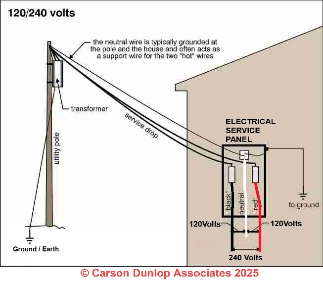
The electric energy generated at a power station or electric utility is transported by wires to the factories, offices, schools, and homes that use it.
Carson Dunlop Associates' sketch at left shows electrical power arriving at a home by overhead wires.
Electrons: The basic building blocks of all matter are atoms.
Electrons are one of the tiny particles that form atoms.
Electrons are the stuff that electrical energy is made of. Some electrons can move from one atom to another.
These are called "free" electrons.
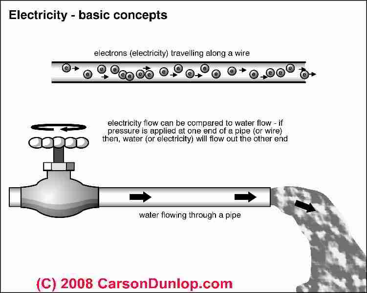
Carson Dunlop Associates' sketch at left shows electrons flowing along a wire, and uses the analogy of water flowing a pipe.
The water pipe analogy for electricity: In our pipe and spigot illustration, no water flows until the spigot is opened (sort of like turning on the electrical switch in a circuit).
Before we opened the spigot the water may have been sitting in the pipe pressing in all directions at 50 psi, but no water flows until we open the spigot.
When we open the spigot, at the input end of our water pipe our water is at 50 psi, but at the open end of the spigot we've just opened, the water pressure is zero - (really 14 psi or one atmosphere at sea level but we'll skip that). So water flows out of the open spigot. Before we opened the spigot we had 50 psi of potential. When we open the spigot a current of water flows out (maybe close to 50 psi if our pump is a really good one.
If we pushed our hand against the open mouth of the spigot with a pressure of 50 psi we could hold the water back, and no water would be flowing, right?
What Makes Electricity "Flow" in an Electrical Circuit
 The short answer is "potential" which is a confusing synonym for "volts" or electrical pressure between an electrical power source (which is pushing at 120V or 240V) and earth (which is sitting at zero V).
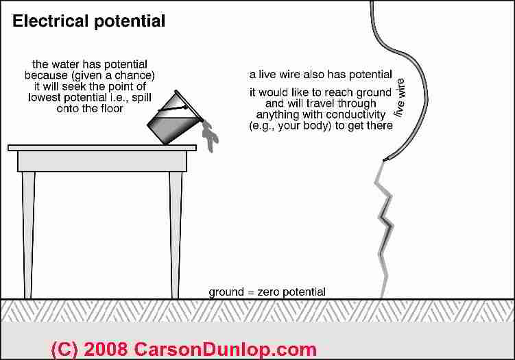
Electrical potential, a concept used to explain electrical voltage or volts, is illustrated at left, courtesy of Carson Dunlop.
The word potential is used to explain that the capacity to do work is present, but not that work is necessarily being performed.
Just above in this article we used a spigot and water pipe analogy to explain the flow of energy through a system, and we said that no water flows if the spigot is shut. We said that the water pressure when the spigot was shut was 50 psi of potential energy flow.
Water in the bucket in our sketch has a capacity to do work (move water, or exert pressure) but until water actually flows out of the bucket (say when it's tipped), no water is moving and no work is being performed. It's just a potential - a word we discuss further with our bucket analogy just below.
In our bucket analogy to explain electricity, shown here, when the bucket is just sitting on the table, the water it contains has the potential to do work (move to the floor), but nothing is happening. No current of water is flowing. As soon as we tip the bucket a current of water (like current in a river) spills out. (Onto the floor in this case, which my mother did not appreciate unless I also had a mop handy.)
Electrical potential or volts: similarly a live electrical wire that is connected to a "hot" electrical power source at just one end, and whose other wire end is not connected to anything (say an electrical switch is open) is not allowing any electrical current to flow. Maybe our wire is connected to a 120 Volt power source - it has 120 Volts of potential waiting to do something but no electrons and no current are flowing. 120 Volts of pressure is pushing at one end of the wire, but since there is no exit path out of the other wire end, no current flows. [Thanks to reader David Hoffman for careful editing - Ed.]
When we close an electrical switch that connects our wire through a light bulb, say, and onwards through wire to the earth, the 120 Volts of pressure or potential begin to successfully push electrons through the wire and electrical current flows through the wire to earth. Literally, earth. The ground. Outdoors. Dirt.
Why is electrical current flowing to earth in an electrical circuit? In our pipe and faucet analogy the water was pressing at 50 psi of potential current and when we opened the faucet to air pressure (which we pretended was at 0 psi), water began flowing from the 50-psi side of the system to the zero psi side.
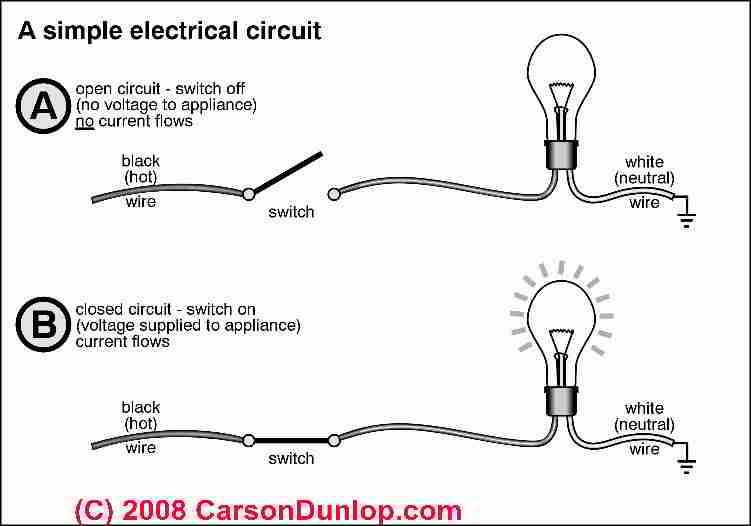
Open circuit: no electrical current flows: In our electrical wire example, when one end of the wire is connected to a power source and the other end is not connected to anything (see the sketch), 120 Volts of potential current is pressing on the wire from the hot or "live" side of the circuit.
Closed electrical circuit: electrical current flows to ground or earth: When we close an electrical switch to let electricity flow through our wire to earth, the earth is at zero potential compared to the electrical wire "hot" source, so a current of electrical energy flows from the "hot" or energy source to the "zero" or "ground" side of the circuit. Yep. Mother earth serves as a zero potential to which we can connect electrical current.
Metal electrical wires: Metals such as copper, steel, and aluminum are called conductors because their atoms have many free electrons and so can conduct electricity efficiently. Wires made of copper, steel, or aluminum provide an ideal way to transport electrical energy with little loss of power.
Insulators: The atoms that make up materials such as rubber, plastic, paper, and wood have almost no free electrons. These materials are called insulators because they cannot conduct electricity. A safe and efficient way to move electric energy, then, is to enclose a wire made of copper, steel, or aluminum in some insulating material and then use the wires to carry electricity from the generateing plant to the final user.
Why do We Need Two Wires for an Electrical Circuit in a Building?
 Electricity is generated by causing all the free electrons in a conductor to move in the same direction.
This creates a surplus of electrons in the atoms of one wire at the output of a generator and a shortage of electrons in the atoms of a second output wire from the generator.
When an electrical device is connected to these two wires, electrons will move along an electrical path through the device in order to restore the natural balance.
Carson Dunlop Associates' sketch at left shows a simple electrical circuit. Most of us think of electricity as "flowing" in one direction (from left to right in our sketch), from the incoming "hot" wire (from the utility company, through our electric meter, into our electrical panel, through our "hot wire"), on through a closed switch (bottom of the sketch), through an electrical device that uses energy (here a light bulb), and continuing through the "neutral" wire down to earth.
In electrical systems using alternating current or "AC" (which is most of the world), the electrical energy is not really flowing in one direction; rather it is reversing direction 60 times a second (60-cycle) or in some countries 50-times a second (50-cycle). AC and DC (direct or unidirectional current) are defined
at ELECTRICAL CIRCUITS, SHORTS.
As long as the generating station at the source continues to operate, the shortage and surplus in the two wires will be maintained and electron movement will continue.
The phrase "current flow" (measured in Amps) is used to describe this electron movement. The rate of the current flow (that is, the number of electrons that pass a point in one second) is measured in units called amperes, or more commonly, amps. The device that measures this current flow is called an ammeter.
The pressure that exists to restore the electron balance (measured in Volts) depends upon how large the difference is between the surplus and the shortage.
The greater the difference, the higher the pressure. This pressure is called voltage and the units in which it is measured are called volts. The device for measuring voltage is called a voltmeter.
Why are Some Electrical Wires Called Hot, Neutral, or Ground Wires?
Hot or Live electrical wires refer to wires that are connected to a source of electrical power. By convention the hot or live wire in residential circuits is usually black or red - but be careful, someone may have mis-wired or used the wrong color wire. If you touch a live wire and are also connected to the earth (standing on it, touching a water pipe, etc) chances are good that you'll receive an electrical shock, potentially a fatal one.
But beware: the neutral wire and even a ground wire (discussed below) are carrying electrical current in some conditions, and are also potential sources of electrical shock, especially if the electrical wiring in a building is defective.
Ground means simply Mother Earth or something connected to earth, such as a cold water pipe in your home or a copper rod driven onto the ground outside your house near where electric power enters.
Literally, electricity in buildings flows from a power source to the earth. In some countries what is called "ground" in the U.S. is called "earth". buildings with safe electrical wire contain one or more local connections to earth, wired from the electrical panel, through a grounding electrode (a ground rod), to the earth. The white or neutral wire is connected to this ground in the electrical panel. (A second "ground" connection in electrical panels connects back to a remote ground or earth connection provided (somewhere) by the utility company.))
See Definitions of Electrical Ground, Grounding Electrode, Grounding Conductor, Grounded Conductor, Ground Wire, Neutral Wire, Ground Rod, for definitions of these confusing electrical terms.
More details about electrical grounding can be read at ELECTRIC SERVICE GROUNDING SYSTEM INSPECTION
and ELECTRICAL CIRCUITS, SHORTS, and at OLD HOUSE ELECTRICAL SYSTEMS.
The earth is such a huge volume of matter that a measurable surplus or shortage of electrons never exists. Earth or ground, therefore, is always electrically neutral.
Ground, and wires connected to ground, can accept electrons or give them up as necessary to cause current to flow between ground and a point at which a shortage or surplus exists.
While both grounding wires and neutral wires are connected to ground, there is a difference in the job each performs in electrical wiring. The job of the ground wire is to provide a path to ground for electric energy when faults occur in the primary power wiring or in electrical devices.
Grounding wires may have green insulation or be bare (no insulation).
Neutral wires: The job of the white wire (neutral) is to provide the normal path for return current flow to the source when no wiring faults exist. The term hot wire refers to the wire with black or red insulation. This is the wire that causes current to flow between it and the neutral wire (or grounding wire if a fault occurs.
Safety Warning:
Watch out: Do not attempt to work on your electrical wiring, switches, or outlets unless you are properly trained and equipped to do so. Electrical components in a building can easily cause an electrical shock, burn, or even death.
Even when a hot line switch is off, one terminal on the switch is still connected to the power source. Before doing any work on the switch, the power source must be turned off by setting a circuit breaker to OFF or removing a fuse.
See SAFETY for ELECTRICAL INSPECTORS
and ELECTRICAL WIRING BOOKS & GUIDES
Questions & Answers about basic home electrical wiring
Question: Which color is the "live" wire in U.S. electrical wiring convention? Is the black wire the "hot" wire?
I am thinking of buying electrical equipment from Chicago. I have already ascertained that it is dual voltage and can accommodate the U.K. mains frequency of 50 HZ.
I may connedct it to0 a U.K. standard electrial plug. In order to obtain the danger of reverse polarity can you please confirm, iof appropriate, that in U.S. electrical flex the LIVE wire is black whilst the neutral wire is white. My information is that the flex for this appliance does not incorporate an Earth wire. - D.H.M. - U.K.
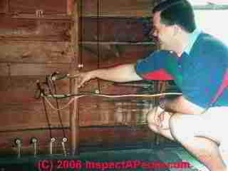
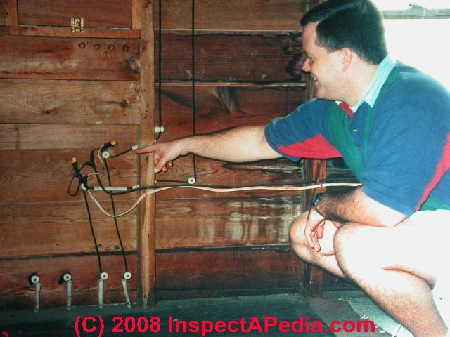
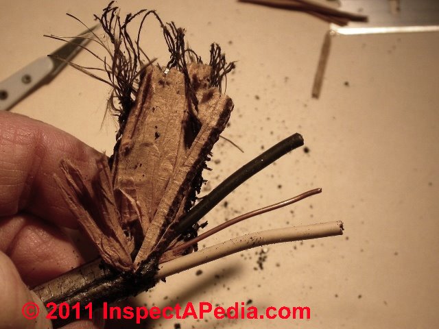
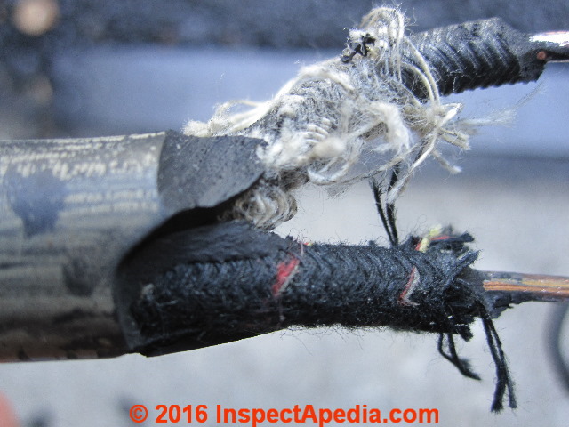
Our photo (left) of older fabric and plastic insulated electrical wiring shows the conventional black ("hot"), white ("neutral") and bare (ground) wires in a fabric and paper insluated exterior jacket.
Reply: Typically the hot wire is black, possibly red, or even white with ends taped to indicate a black-hot wire
A competent onsite inspection by an expert usually finds additional clues that help accurately diagnose a problem.
That said, convention in the U.S. is that the black wire is hot and the white wire is neutral.
Watch out: There are exceptions to the basic home electrical wiring color convention: a red wire may also be "hot" or "live" in a shared neutral or 240V circuit.
And light switches may use the white (usually neutral) wire to carry current to one side of the switch to or from the light fixture. Good practice where the white wire is "hot" is to tape the ends with black electrical tape to give a clue to the next person working on the wiring system.
Also older fabric or rubber covered electrical wiring may follow the black/white convention, but the colors may have been lost from the wiring insulation, or the white insulation difficult to spot, or the "hot" wire may be marked with a red stripe woven into the fabric insulation (photo at left).
But knowing absolutely nothing about the specific equipment or devices you are discussing, my best advice is to take a look at the equipment wiring diagrams from the manufacturer - typically it's easy to get these from the manufacturer or even their website. Or you can inspect the equipment's actual wiring.
...
Continue reading at ELECTRICAL CIRCUIT ID, MAP & LABEL or select a topic from the closely-related articles below, or see the complete ARTICLE INDEX.
Or see these
Recommended Articles
- DMM DIGITAL MULTIMETER HOW TO USE
- DMMs VOMs SAFE USE OF
- DO IT YOURSELF ELECTRICAL WORK
- ELECTRICAL CIRCUIT ID, MAP & LABEL
- ELECTRICAL DEFINITIONS
- ELECTRICAL INSPECTION, DIAGNOSIS, REPAIR - home
- ELECTRIC LIGHT SWITCH WIRING DETAILS
- ELECTRIC PANEL INSPECTION SAFETY
- ELECTRIC POWER LOSS / FLICKERING LIGHTS
- ELECTRICAL OUTLET, HOW TO ADD & WIRE - home
- ELECTRICAL RECEPTACLE CONNECTION DETAILS
- ELECTRICAL WIRING BASICS
- SAFETY for ELECTRICAL INSPECTORS - home
Suggested citation for this web page
ELECTRICAL BASICS at InspectApedia.com - online encyclopedia of building & environmental inspection, testing, diagnosis, repair, & problem prevention advice.
Or see this
INDEX to RELATED ARTICLES: ARTICLE INDEX to ELECTRICAL INSPECTION & TESTING
Or use the SEARCH BOX found below to Ask a Question or Search InspectApedia
Ask a Question or Search InspectApedia
Try the search box just below, or if you prefer, post a question or comment in the Comments box below and we will respond promptly.
Search the InspectApedia website
Note: appearance of your Comment below may be delayed: if your comment contains an image, photograph, web link, or text that looks to the software as if it might be a web link, your posting will appear after it has been approved by a moderator. Apologies for the delay.
Only one image can be added per comment but you can post as many comments, and therefore images, as you like.
You will not receive a notification when a response to your question has been posted.
Please bookmark this page to make it easy for you to check back for our response.
IF above you see "Comment Form is loading comments..." then COMMENT BOX - countable.ca / bawkbox.com IS NOT WORKING.
In any case you are welcome to send an email directly to us at InspectApedia.com at editor@inspectApedia.com
We'll reply to you directly. Please help us help you by noting, in your email, the URL of the InspectApedia page where you wanted to comment.
Citations & References
In addition to any citations in the article above, a full list is available on request.
- "Electrical System Inspection Basics," Richard C. Wolcott, ASHI 8th Annual Education Conference, Boston 1985.
- "Simplified Electrical Wiring," Sears, Roebuck and Co., 15705 (F5428) Rev. 4-77 1977 [Lots of sketches of older-type service panels.]
- "How to plan and install electric wiring for homes, farms, garages, shops," Montgomery Ward Co., 83-850.
- "Simplified Electrical Wiring," Sears, Roebuck and Co., 15705 (F5428) Rev. 4-77 1977 [Lots of sketches of older-type service panels.]
- "Home Wiring Inspection," Roswell W. Ard, Rodale's New Shelter, July/August, 1985 p. 35-40.
- "Evaluating Wiring in Older Minnesota Homes," Agricultural Extension Service, University of Minnesota, St. Paul, Minnesota 55108.
- "Electrical Systems," A Training Manual for Home Inspectors, Alfred L. Alk, American Society of Home Inspectors (ASHI), 1987, available from ASHI. [DF NOTE: I do NOT recommend this obsolete publication, though it was cited in the original Journal article as it contains unsafe inaccuracies]
- "Basic Housing Inspection," US DHEW, S352.75 U48, p.144, out of print, but is available in most state libraries.
- Elizabeth Sluder, Montross, VA, the original author of this article, is a public school teacher who writes basic educational articles about a variety of building, construction, and other topics. Her husband, a licensed electrician, consults for her writing on electrical topics. Her articles appearing at the InspectAPedia TM Website have been edited, illustrated, and on occasion content has been added by the website author. These articles are © 2010 InspectAPedia copyright-protected, all rights reserved.
- Mark Cramer Inspection Services Mark Cramer, Tampa Florida, Mr. Cramer is a past president of ASHI, the American Society of Home Inspectors and is a Florida home inspector and home inspection educator. Mr. Cramer serves on the ASHI Home Inspection Standards. Contact Mark Cramer at: 727-595-4211 mark@BestTampaInspector.com
- John Cranor [Website: /www.house-whisperer.com ] is an ASHI member and a home inspector (The House Whisperer) is located in Glen Allen, VA 23060. He is also a contributor to InspectApedia.com in several technical areas such as plumbing and appliances (dryer vents). Contact Mr. Cranor at 804-873-8534 or by Email: johncranor@verizon.net
- Thanks to reader David Hoffman for careful editing and text suggestion, 7/17/12
- In addition to citations & references found in this article, see the research citations given at the end of the related articles found at our suggested
CONTINUE READING or RECOMMENDED ARTICLES.
- Carson, Dunlop & Associates Ltd., 120 Carlton Street Suite 407, Toronto ON M5A 4K2. Tel: (416) 964-9415 1-800-268-7070 Email: info@carsondunlop.com. Alan Carson is a past president of ASHI, the American Society of Home Inspectors.
Thanks to Alan Carson and Bob Dunlop, for permission for InspectAPedia to use text excerpts from The HOME REFERENCE BOOK - the Encyclopedia of Homes and to use illustrations from The ILLUSTRATED HOME .
Carson Dunlop Associates provides extensive home inspection education and report writing material. In gratitude we provide links to tsome Carson Dunlop Associates products and services.
 | HOME | ABOUT | ASK a QUESTION | CONTACT | CONTENT USE POLICY | DESCRIPTION | POLICIES | PRIVACY | |
| © 2024 - 1985 Publisher InspectApedia.com - Daniel Friedman | |||||||||