 Barrier Wall Construction vs Cavity Wall Building Construction Methods
- POST a QUESTION or COMMENT about barrier wall vs. cavity wall and rain/screen wall construction methods
Barrier wall and cavity wall construction methods:
This article describes the two design approaches to keeping water and moisture out of building exterior walls: designing barrier walls (the exterior skin is waterproof) and designing cavity / rain-screen walls (the wall is designed to get rid of water that penetrates it).
Here we define and describe these approaches and we illustrate what can go wrong with each of them, leading to building leaks and mold or structural damage.
InspectAPedia tolerates no conflicts of interest. We have no relationship with advertisers, products, or services discussed at this website.
- Daniel Friedman, Publisher/Editor/Author - See WHO ARE WE?
Barrier Wall Construction vs Cavity Wall Building Construction Methods
 Definitions of Barrier Wall Construction and Cavity Wall Construction
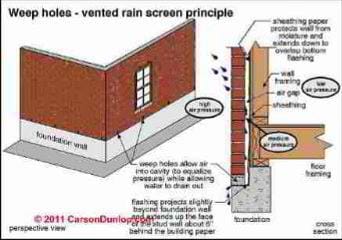
To diagnose a building water entry or moisture problem originating at its exterior walls we must first understand the construction concepts that were used to build that wall: two very different concepts apply, though they often appear mixed or even confused in buildings. Page top illustration courtesy of Carson Dunlop Associates, a Toronto home inspection, education & report writing tool company [ carsondunlop.com ].
[Click to enlarge any image]
Williams & Williams stated these definitions most clearly: [1]
Definition of barrier wall construction
A barrier wall is designed and constructed to shed all water, thereby preventing any moisture from penetrating beyond the outermost surface and into the wall itself. Barrier walls are essentially moisture-tight constructions. Beneath the barrier's outer skin, the underlying materials and building interior are kept dry. [1]
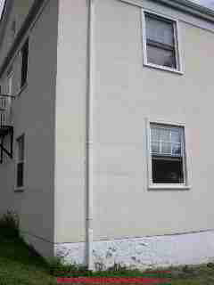
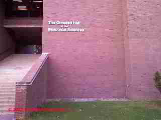
Our photo (left) illustrates a barrier wall constructed building - Bard College South Hall, Annandale NY, photographed in 2005. The wall was intended to shed all water but our inspection found vulnerabilities and leaks traced to original construction errors and to mechanical damage. A common example: installation of exterior wall lighting fixtures after construction punches and leaves un-sealed holes in the exterior wall face.
Examples of barrier wall constructions are architectural pre-cast concrete, most EIFS (Exterior Insulation & Finish Systems - STUCCO EIFS DRAINAGE SYSTEMS), and single-wythe masonry walls.
The vulnerability of a barrier wall construction system to leaks and water entry is that because the wall does not make any provision whatsoever for handling water that penetrates the wall (due to a construction error, mechanical damage, wear and tear, etc.), once any water has leaked into the wall damage will follow, occurring as mold contamination, rot (rot is caused by wood destroying fungi), or an invitation for insect attack.
Definition of cavity wall construction: difference between the cavity approach and the rain screen approach
Cavity / rain screen walls also shed water at the outer face; however, this wall concept anticipates some degree of water intrusion by including internal drainage provisions. Specifically, an air space situated between the inner and outer wall components forms a "cavity". The dimension of this air space depends on the version of the cavity / rain screen concept implemented in the wall. [1]
 Our photo (left) illustrates a cavity-wall construction - Eula Hall on the Vassar College Campus.
In 2009 when we took this photo, decades of water running down the wall face (from a gutter leak) had led to extensive frost damage to the wall. We left that brick turned on-end as a clue for site maintenance staff but in fact the facilities management crew were well aware of the conditions here.
By 2012 the college had the wall rebuilt. There are two approaches to cavity wall construction: cavity and rain screen. Continuing with help from Williams and Williams:
In the cavity wall version, the air space, detailed with flashing and drainage features, returns water to the building exterior. In its most basic form the air space relies on the force of gravity to collect and redirect water to the building exterior.
To function properly, the space must be unobstructed. Any blockage or obstacle within the space hinders the collection and proper discharge of water. [1]
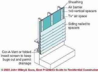
The Carson Dunlop Associates sketch at page top also illustrates the cavity wall approach to construction. The sketch at left, courtesy of Steven Bliss & J Wiley & Sons, illustrates use of the rain-screen approach on a clapboard-sided structure. The rain-screen system in this sketch has four components: an exterior cladding, an air space, a drainage plane, and weep holes. [14]
In the rain screen version, the air space serves as a means of wall drainage as well as a means of equalizing air pressure in the space. An air-tight barrier is placed within the inner layer of the wall construction. The air barrier and specialized vents equalize pressure differences between air inside the cavity and outside the building. [1]
The air space between the inner wall structure and the outer wall veneer is designed wider in the cavity wall approach than in the rain screen approach. In fact the rain screen approach
... necessitates a narrower, compartmentalized air space. This reduces the volume of air in the space and increases the rate of pressure equalization.[1]
In the field, a very common instance of blockage of the wall cavity drainage system begins at the time of construction. In constructing a brick masonry veneer, the mason, working to place bricks from the exterior side of the wall, places excess mortar atop each brick in each course. On the wall exterior face the mason cuts away any excessive mortar from the joint before the joint is then tooled.
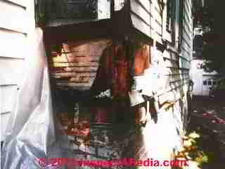
An example of what happens when water is trapped in a structural brick wall cavity is illustrated at left. The author repaired this wall in the 1980's. Leaks into the wood frame wall from above ran through the brick foundation wall cavity below.
The same brick foundation wall cavity that was attempting to drain that large volume of water also provided an inviting highway for carpenter ants to enter and attack the wall structure from below. We had to re-frame the wall corner, replace wall sheathing and insulation, and of course fix the yankee gutter leaks at an inside corner roof structure above.
During construction, on the wall interior, in the cavity side, excess mortar can block the wall cavity in-situ, or more commonly, much of this mortar actually falls down inside the brick veneer cavity where it blocks the weep holes at the wall bottom. If the space between the outer veneer and inner wall is wide enough, the blockage of falling mortar is minimized. How wide is that? It depends.
Any renovation contractor (such as the author, DF) who has disassembled a brick veneer wall or a structural brick wall built with a wall cavity, has found substantial blockage in at least a good part of the wall cavity. W&W continue:
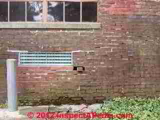
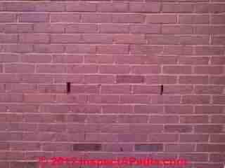
At below left we show a brick wall (a veneer in this case) with weep openings at regular intervals at two heights above ground level. Below right is a closeup of one of the drainage openings. Veneer wall weep openings are placed at least at the very bottom of the brick veneer wall cavity. We suspect that the wall cavity does not extend lower than the weep holes in our photo - why? The lower brick courses were probably laid tight, with no cavity at all, against a solid concrete or masonry block foundation wall.
Many Brick or Stone Veneer Walls are Barrier Walls not Cavity / Rain Screen Walls
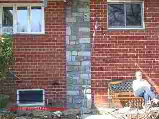
The brick walls of the New York home in our photo at below left contain no weep openings. Bricks were laid tight against a solid masonry block wall with "faux" bond courses to the left of the chimney and all stretcher brick courses to the right of the chimney. Walls both left and right of the chimney were constructed with no drainage. Bricks were mortared against the masonry block structural walls of the home with no air space and no drainage provision.
This is a brick veneer on block structure approximately 30 years old. While the mason omitted weep openings, we did not find any evidence of water or frost damage to the brick veneer except at another wall where splash-up from roof spillage had worn mortar joints. This is a barrier wall design, not a cavity / rain-screen wall designed structure.
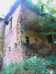
Traditional structural brick walls such as at the building shown at above right are comprised of two or more wythes [defined below] of brick laid in parallel and reinforced by bond courses at regular intervals. Such walls typically include an air gap between the exterior wythes of brick - the wall outside surface, and the wall interior.
That space allowed water that leaked into the wall to run down the
At BRICK FOUNDATIONS & WALLS we describe the collapse of the structural brick walled building shown at above right.
Readers can compare air and water barrier concepts
at WATER BARRIERS, EXTERIOR BUILDING
In addition to VAPOR BARRIERS & HOUSEWRAP, readers should
also
see HOUSEWRAP INSTALLATION DETAILS
...
Continue reading at BRICK STRUCTURAL WALLS LOOSE, BULGED or select a topic from the closely-related articles below, or see the complete ARTICLE INDEX.
Suggested citation for this web page
WALL CONSTRUCTION BARRIER vs CAVITY at InspectApedia.com - online encyclopedia of building & environmental inspection, testing, diagnosis, repair, & problem prevention advice.
Or see this
INDEX to RELATED ARTICLES: ARTICLE INDEX to BUILDING STRUCTURES
Or use the SEARCH BOX found below to Ask a Question or Search InspectApedia
Ask a Question or Search InspectApedia
Try the search box just below, or if you prefer, post a question or comment in the Comments box below and we will respond promptly.
Search the InspectApedia website
Note: appearance of your Comment below may be delayed: if your comment contains an image, photograph, web link, or text that looks to the software as if it might be a web link, your posting will appear after it has been approved by a moderator. Apologies for the delay.
Only one image can be added per comment but you can post as many comments, and therefore images, as you like.
You will not receive a notification when a response to your question has been posted.
Please bookmark this page to make it easy for you to check back for our response.
IF above you see "Comment Form is loading comments..." then COMMENT BOX - countable.ca / bawkbox.com IS NOT WORKING.
In any case you are welcome to send an email directly to us at InspectApedia.com at editor@inspectApedia.com
We'll reply to you directly. Please help us help you by noting, in your email, the URL of the InspectApedia page where you wanted to comment.
Citations & References
In addition to any citations in the article above, a full list is available on request.
- In addition to citations & references found in this article, see the research citations given at the end of the related articles found at our suggested
CONTINUE READING or RECOMMENDED ARTICLES.
- Carson, Dunlop & Associates Ltd., 120 Carlton Street Suite 407, Toronto ON M5A 4K2. Tel: (416) 964-9415 1-800-268-7070 Email: info@carsondunlop.com. Alan Carson is a past president of ASHI, the American Society of Home Inspectors.
Thanks to Alan Carson and Bob Dunlop, for permission for InspectAPedia to use text excerpts from The HOME REFERENCE BOOK - the Encyclopedia of Homes and to use illustrations from The ILLUSTRATED HOME .
Carson Dunlop Associates provides extensive home inspection education and report writing material. In gratitude we provide links to tsome Carson Dunlop Associates products and services.

