
 Cape Cod Cottage House Plans
Chapter 24 of How to Build Your Dream Home © 2020 InspectApedia.com

- POST a QUESTION or COMMENT about how to identify the architectural style of buildings and building components
Chapter 24 of BUILD YOUR DREAM HOME
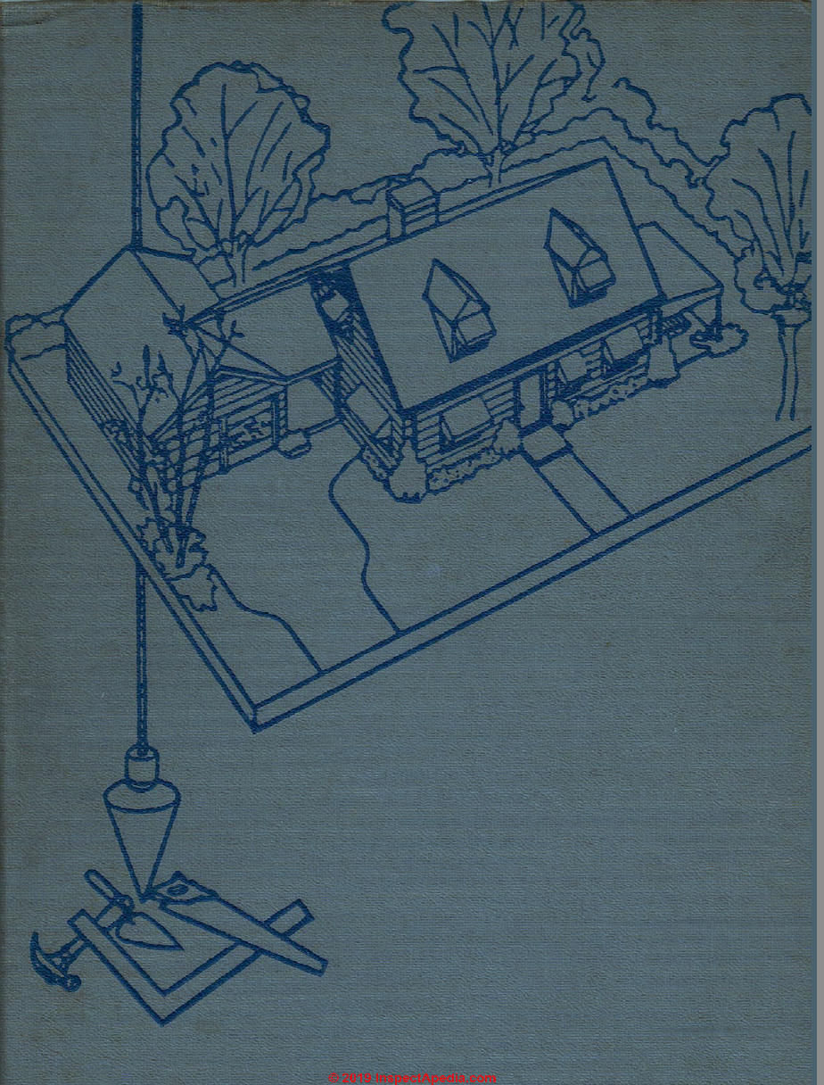
This article series provides an updated version of Hubbard Cobb's Your Dream Home, illustrated by Sigman-Ward, first published by Wm. H. Wise & Co. New York, 1950.
From site selection and obtaining financing through each step in construction of a single family home the simple procedures and drawings in this book are still useful for anyone building or repairing a home or other small structure.
InspectAPedia tolerates no conflicts of interest. We have no relationship with advertisers, products, or services discussed at this website.
- Daniel Friedman, Publisher/Editor/Author - See WHO ARE WE?
Chapter 24
A CAPE COD COTTAGE
|
As you can see from the plans, this cottage is very similar to the basic house in appearance as well as construction. While it is somewhat smaller than ♦ the basic house and does not have a second floor that can be used for living purposes, the first floor has been planned to provide ample space for a small family. Eliminating the attic room and the dormer windows decreases the cost of this house considerably in comparison with the basic house. Examine the first-floor plan of the Cape Cod Cottage and you will see that all the really important features of the basic house are there. There are two good-size bedrooms and a spacious living room with a fireplace for luxurious living. Ample space has been given to the kitchen, and the bath, while compact, is most adequate. There is plenty of closet space in each bedroom, and there is also a storage closet in the kitchen. The utility room off the kitchen contains the heating equipment and the hot-water heater. |
Although the attic space is not practical for use as living quarters, it can be used very handily for storage purposes. The access to the attic is through an opening in the first-floor ceiling. This opening is fitted with a trap door. The Cape Cod Cottage is an excellent house for a small family. It is bv no means merely a summer home but has been planned for all-year-round living. Foundations and Floor Slab The first floor of the house is poured concrete, which is covered with asphalt tile after all the rest of the house has been completed. If the floor is properly constructed according to the directions given in the chapter on pouring slab floors, it will be dry and comfortable % both winter and summer. Information required for building the house foundations is given in the foundation plan. The foundation walls can be either poured concrete or masonry blocks. They are set on a footing that extends below the frost line. Running through the approximate center of the house is a footing for the main bearing partition and for the fireplace base. This footing does not have to extend more than 12" in depth as it will not be subject to frost. Heavy |
|
-V cl |  |
|
unbroken lines on the foundation plan indicate the foundation itself, while the broken light lines indicate the footings. Once the foundations have been poured, two 2" x 4"s should be anchored to the top of the foundation wall to serve as a sill and a nailing base for the wall partition. When these are in place, the ground can be prepared to receive the concrete-slab floor. The floor, as you will note from the longitudinal section, is 4" thick and the top comes level with the top of the sole plate. It is poured over a 8" base of cinders or gravel, well tamped. Kefer to the section in this book that deals with pouring concrete-slab floors to see exactlv how the floor is insulated from the foundation walls before the concrete is poured and what methods should be used to waterproof the floor. Framing When the concrete is hard, the house frame can be erected. Studv the four #• framing plans for the avails to learn the manner in 'which the Avail studding is put up. Wall studding should be 7TM*" high. The four framing-elevation plans show the rough openings for the doors and windows. As is the case w'ith the other houses covered in this book, the dimensions for the AvindoAv rough openings apply to a particular brand of Avood casement AvindoAv. If the brands of casements available at A7our •• local lumber \rard do not fit these * dimensions, make the rough openings to match the available casements. |
You will find it a good deal easier to frame all four Avails and complete the roof and then go hack and cut out the openings in the studding for the doors and windows than to try to make them before you erect the walls. After the four walls are in place, go to wfork on the main bearing partition. It should be the same height as the outside A\Talls, as it is going to support the ends of the ceiling joists. When the bearing partition is in place, the ceiling joists can be installed. The ceiling framing plan will provide most of the necessar\7 information atou %T • will need. The joists can be 2"x6"s since their span is not Arery great and the attic is to be used onh7 for limited % storage space. Openings will be required in the ceiling for the fireplace and furnace chimney and also for an access panel for the attic. The ceiling framing plan show's the exact location of the opening for the chimney as Avell as the necessan7 • • dimensions. Note that the joists on each side of the opening are double and that double headers are used at the ends of these joists. The joists around the opening for the access panel do not haA7e to be doubled because the ends of the tail joists Avill be supported a short distance back by one of the interior wall partitions. The next step is to install the rafters on the roof. You will be able to get by with 2"x6"s because here also the * span is not very great and additional supports will be put between the rafters and the ceiling joists. |
 |
General Floor Plan of the Cape Cod Cottage |
|
These additional supports are shown in the left and right side framing-elevation plans. They consist of 2" x 4"s and they run diagonally down from horizontal 2" x 4"s that are spiked into the rafters. These horizontal 2"x4"s should run the entire length of the roof on both sides. The supports from this beam to the ceiling joists should be installed every three rafters. Once the rafters are in place, go ahead and install the studding at the gable ends. The louver located near the ridge at each gable end can be a stock item purchased at any lumber yard. When making the opening for the louver, be sure that when it is put in place it wdll be properly centered. The openings for the doors and windows should now be made if they were not done while framing the walls. Next, wall sheathing and roof boards should be installed. Fireplace and Furnace The dimensions for the fireplace in this house are the same as those given for the basic house in the chapter on building a fireplace. Since the fireplace is built up from the concrete footing, which is at floor level, it will not be necessary to construct any fireplace or chimney base. The heating system is located in the utility room, so a second flue in the chimney must be installed just above the fireplace opening to take care of the furnace stove pipe. |
The size of the fireplace and chimney and their location in relation to the rest of the house are given in the first-floor plan. The size of fluetile for the furnace is given in the ceiling framing plan as 8" x 1". This should be sufficient for ordinary heating equipment. It may be possible to use a smaller size of flue-tile, in which case the chimney can be built out to the proper dimensions with additional bricks and mortar. When the chimney has been com-pleted, you can install the roofing material. Asphalt shingles are about the best bet as far as economy and appearance go, but if you wish, you can use wood or asbestos shingles. Siding and Insulation The frame of the house should be covered with a high-grade building paper, after which the window7 and door frames are installed. When they arc in place, the exterior siding can go on. The elevation plans show the house as covered with bevel siding, but drop siding or w7ood or asbestos shingles can also be used. Plywood would likewise be suitable. In as much as this house is to be used for year-round living, insulation for the walls an<T ceilings is most important. The attic floor, rather than the roof, should be insulated, as there is no point in wasting fuel to heat the attic storage space. It will also require less insulation to cover the floor than to cover the rafters. Before you go to work on installing the interior wall partitions, refer to the first-floor plan, which gives the exact location of these as w'ell as the size of |
|
the necessary openings for doors and closets. Note that the studding for one wall of the bathroom is made out of 2" x 6"s in order to allow a 4" cast-iron soil pipe to pass up through it. |
ampere branch circuits and two 20-am-pere appliance circuits for the kitchen and the portion of the living room that is to serve as a dining area. You may require individual circuits also for the kitchen range, hot-water heater and laundry equipment. Plaster or a good grade of wallboard |
|
Utilities Once the bathroom walls have been | |||||||||||||||||||||||||||||||||||||||||||||||||||||||||||||||||||||||||||||||||||||||
| |||||||||||||||||||||||||||||||||||||||||||||||||||||||||||||||||||||||||||||||||||||||
Material
Interior doors with trim, jambs and stops
Casement picture window with sash and frame
Casement window with sash and trim
Clay flue-tile Copper flashing
Quantity
2
3 2 2 1 2 2
2
4
3
4 sections 4 sections 2 pieces
1 piece
Dimensions
r 10" x 6'8"
1' 8" x 6'8"
2' 0"x6'8"
r 5"x6'8"
r 6"x6'8"
10" x 6'8"
12" x 6'8"
4'2%" x 6'5%" 4'2%" x 3'1%" 3'2%6"x3'l%" 12" x 12" x 2' 12" x 8" x 2' 12"x12"
4' x 4'
|
Louvers, 2 Gutters, 64' Nails: 6d, 24 lbs; 8d, 30 lbs; 16d, 18 lbs; finish, 20 lbs; 4>d, 48 lbs; 5d, 9 lbs Hinges: 6 brass; 36 interior Mortice locks, 9 Latches, 9 Common bricks, 2,000 Firebricks, 100 Fireclav, 30 lbs. Clean-out doors, 2 Chimney thimble * Cement mortar, 1 cu. yd. Damper Angleirons: 1, 42"; 1,36" Ash-dump Hearth assembly Mixed cement, 2 cu. ft. Paint: exterior, 24 gal.; water-thinned, 11 gal.; enamel, \ V> gal.; floor, 3 gal. Steel boiler (96,000 BTU) with jacket with 200-gal. per hour coil Fill box |
Vent cap Ventalarm 12 x 30 compression tank Airtrol tank fitting Autovent with overflow 114" angle flow control No. 8 dual valve %" stop and waste valve Circulator %" type L copper tubings, 1,000 4" x 4" sanitary T branch 4" x 4" Y branch 4" clean-out plug 4" x 4" sanitary T branch with 2" tap ping o sections 4" cast-iron soil pipe, 8 Inereaser 4" closet bend Kitchen sink Bathtub with shower and fittings Lavatory with fittings Water closet with flush tank and fittings |


 |
Foundation Plan of the Cape Cod Cottage |

Front Elevation of the Cape Cod Cottage
GUTTER
BRICKS
FLASH ING
12
|
WOOD SIDING | ||||||||||||||||||||||||||||||||||||||||||||||||||||||||||||||||||||||||||||||||||||||||||||||||||||||||||||||||||||||||||||||||||||||||||||||||||||||||||
| ||||||||||||||||||||||||||||||||||||||||||||||||||||||||||||||||||||||||||||||||||||||||||||||||||||||||||||||||||||||||||||||||||||||||||||||||||||||||||
I
rC
2y-&
2
<X>
i
7^
 |
|
GRADE |
RIGHT SIDE ELEVATION
SCALE yife-sT-O''
|
BRICK |  |
Rear Elevation of the Cape Cod Cottage |

GRADE |
|
n | ||||
|
1 | ||||
|
-—■ GLASS | ||||
|
1 t | ||||
|
2-io‘x G-8“ CLUSW DOOR | ||||
|
_ | ||||
|
1........ | ||||
WOOD SIDING
POWN^POUT
|
-23’ - 8“ | |
LEPT SIDE ELEVATION
SCALE 3/|fo"= l-O"
 |
Floor Plan of the Cape Cod Cottage |

Front Framing Elevation of the Cape Cod Cottage
CAPE COD COTTAGE

|
2’x4"s | |
 |
2~*<o' RAFTERS 2Tx4-S |
|
j__FOOT ING 23-a" FOUNDATION SILL | |
RIGHT SIDE FRAMING ELEVATION
SCALE ^"Vr-o*

o
D
Z
D
O
iL
o
>
LU r
-I O
LU -1 il
—
So,
< -J
rv <
LL U
O'
<
111
a.
Rear Framing Elevation of the Cape Cod Cottag

|
-.•» . rt 2*4S 2’RAFTERS _« .»» 2*45 PLATE |
 |
|
. tl 2*4 DOUBLED |
 |
U- l'/<2 |
<N
 |
SILL |
FOUNDATION
f'x 4“ BRACING LET INTO CAGE OP STUDDING
23’- S"
FOOTING
LEET SIDE FRAMING ELEVATION
SCALE 3/ifc," = 1*0“
Left Side Framing Elevation of the Cape Cod Cottage

|
b U H | ||||||||||||||||||||||||||||||||||||||||||||||||||||||||||||||||||||||||
| ||||||||||||||||||||||||||||||||||||||||||||||||||||||||||||||||||||||||
|
0-,Qx9* z % I H' *» '-A | ||||||||||||||||||||||||||||||||||||||||||||||||||||||||||||||||||||||||
0
1
II
=^>
5:
tn
01
—i
<
U
w
0-*7l*9*C
w
0 . I
<0
■>o
sO
'ȣ>
|
r |
La | ||
|
L | |||
|
--r | |||
:C0
vD
CS
|
OJ | |||||||||||||||||||||||||||||||||||||||||||||||||||||||||||||||||||||
|
** / | ||||||||||||||||||||||||||||||||||||||||||||||||||||||||||||||||||||||
Ceiling Framing Plan of the Cape Cod Cottage

Longitudinal Section of the Cape Cod Cottage
...
Continue reading at COLONIAL HOUSE PLANS - next chapter in this book, or go to book contents at BUILD YOUR DREAM HOME, or select a topic from the closely-related articles below, or see the complete ARTICLE INDEX.
Or see these
Recommended Articles
- ARCHITECTURE & BUILDING COMPONENT ID - home
- ARCHITECTURE DICTIONARY of BUILDINGS & COMPONENTS
- ARCHITECTURAL STYLE & BUILDING AGE
- BUILD YOUR DREAM HOME
- CONSTRUCTION DICTIONARY
- GLOSSARY of BUILDING TERMS
- HOME CONSTRUCTION CATALOGS 1950
- KIT HOMES, Aladdin, Sears, Wards, Others
Suggested citation for this web page
CAPE COD COTTAGE PLANS at InspectApedia.com - online encyclopedia of building & environmental inspection, testing, diagnosis, repair, & problem prevention advice.
Or see this
INDEX to RELATED ARTICLES: ARTICLE INDEX to BUILDING ARCHITECTURE
Or use the SEARCH BOX found below to Ask a Question or Search InspectApedia
Or see
INDEX to RELATED ARTICLES: ARTICLE INDEX to BUILDING DAMAGE, DISASTER, REPAIRS
Or use the SEARCH BOX found below to Ask a Question or Search InspectApedia
Ask a Question or Search InspectApedia
Share this article:Questions & answers or comments about how to identify the architectural style of buildings and building components
Try the search box just below, or if you prefer, post a question or comment in the Comments box below and we will respond promptly.
Search the InspectApedia website
Note: appearance of your Comment below may be delayed: if your comment contains an image, photograph, web link, or text that looks to the software as if it might be a web link, your posting will appear after it has been approved by a moderator. Apologies for the delay.
Only one image can be added per comment but you can post as many comments, and therefore images, as you like.
You will not receive a notification when a response to your question has been posted.
Please bookmark this page to make it easy for you to check back for our response.
IF above you see "Comment Form is loading comments..." then COMMENT BOX - countable.ca / bawkbox.com IS NOT WORKING.
In any case you are welcome to send an email directly to us at InspectApedia.com at editor@inspectApedia.com
We'll reply to you directly. Please help us help you by noting, in your email, the URL of the InspectApedia page where you wanted to comment.
Citations & References
In addition to any citations in the article above, a full list is available on request.
- In addition to citations & references found in this article, see the research citations given at the end of the related articles found at our suggested
CONTINUE READING or RECOMMENDED ARTICLES.
- Carson, Dunlop & Associates Ltd., 120 Carlton Street Suite 407, Toronto ON M5A 4K2. Tel: (416) 964-9415 1-800-268-7070 Email: info@carsondunlop.com. Alan Carson is a past president of ASHI, the American Society of Home Inspectors.
Thanks to Alan Carson and Bob Dunlop, for permission for InspectAPedia to use text excerpts from The HOME REFERENCE BOOK - the Encyclopedia of Homes and to use illustrations from The ILLUSTRATED HOME .
Carson Dunlop Associates provides extensive home inspection education and report writing material. In gratitude we provide links to tsome Carson Dunlop Associates products and services.
 |
HOME | ABOUT | ASK a QUESTION | CONTACT | CONTENT USE POLICY | DESCRIPTION | POLICIES | PRIVACY | |
| © 2026 - 1985 Publisher InspectApedia.com - Daniel Friedman | |||||||||