
InspectAPedia® FREE Encyclopedia of Building & Environmental Construction, Diagnosis, Maintenance & Repair |
Question? Just ask us! InspectAPedia
|
 Water Pump Wiring Troubleshooting & Repair
Well pump wiring diagrams, 3-wire, 4-wire, Install or detect & fix well pump control box & wiring for 2-wire, 3-wire & 4-wire pump installations
- POST a QUESTION or COMMENT about checking electrical wiring to diagnose well pump problems such as tripping breakers, blown fuses, weak pump performance or no water delivery from a well water pump
Well pump wiring diagnosis & repair:
This article describes troubleshooting a submersible well pump that was causing tripped circuit breakers and that pumped water only at a slow, reduced rate and pressure, and includes well pump wiring diagrams and instructions.
Ultimately using some simple electrical tests the homeowner traced the water pump problems to a nicked well pump wiring circuit wire.
InspectAPedia tolerates no conflicts of interest. We have no relationship with advertisers, products, or services discussed at this website.
Electrical Wiring Damage Causing Water Pump Malfunctions: breaker or fuse trip/blow, poor or weak pump performance
 Here we explain how to check voltage, current, resistance to help diagnose well pump problems such as tripping breakers, blown fuses, weak pump performance or no water delivery from a well water pump.
Further below on this page we include wiring diagrams for 115/230V well pumps with diagrams for 2-wire pumps, 3-wire pumps, and 4-wire well or water pump installations.
How to install & wire a pump control box.
[Click to enlarge any image]
Watch out: electrical wiring is dangerous: you could be shocked or killed. If you are not trained and familiar with proper, safe electrical wiring practices don't try it;
On 2018-12-26 by (mod) - how to test a submersible well pump wiring and motor - typical resistance values
This sounds to me as if the motor is overheating or is damaged and is drawing high current (amps).
There are at least two common electrical tests:
1. A test of the pump wiring
itself for deteriorated or damaged insulation (low resistance), breaks (infinite resistance), and dead shorts to ground (zero or close to zero resistance)
2. A test of the pump motor windings
for evidence of wear or shorts (abnormally low resistance)
Tests of the pump wiring are made by individually connecting between each wire (at the well head) and ground.
If the well casing is metal then connect the ground lead of the VOM/DMM (be sure it's a good clean connection) to the well casing or metal piping). If the well casing is plastic then you have to connect your ground lead to the circuit ground.
I give some examples below.
It's difficult to make an exhaustive check of the wires for leaks or weak shorts to ground without pulling the wiring out of the well since at the wire ends there will be a connection through the pump motor - giving some resistance but not a quantity that we know without help from the pump manufacturer.
Watch out: if you do not know how to perform electrical wiring and circuit tests safely you could be shocked or killed or could start a building fire. Work with power off and disconnected from the pump circuit.
See DMMs VOMs SAFE USE OF
With power OFF and wires to the pump DISCONNECTED at the house end so that there is no power to the pump or controls,
AND provided you know how to use a DMM or VOM safely - as you could be killed if you make a mistake in wiring -
you or your electrician might use the DMM or VOM in Ohms mode to measure the circuit resistance.
You need to know the normal resistance for your specific well pump brand and model.
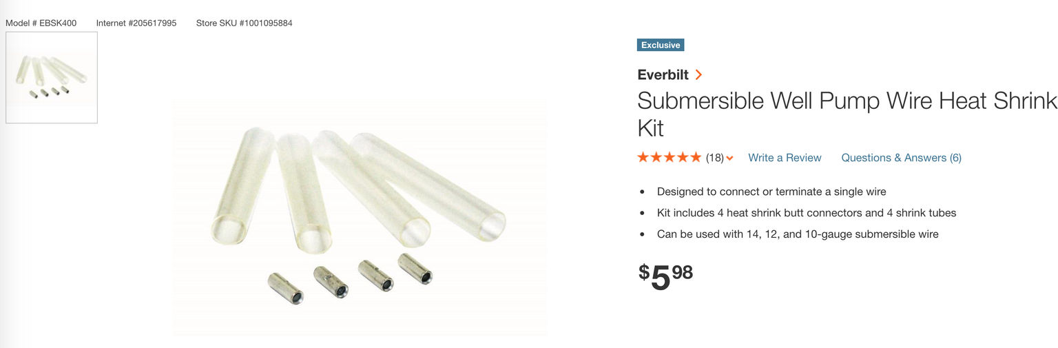
\Illustration: a waterproof electrical wiring splice kit sold at Home Depot stores, electrical suppliers, plumbing suppliers.
You need to know the approximate total length of the wire as there is a correction factor to include for wire length.
- Before allowing for wire length, for EXAMPLE, a #10 copper pump wire will have about 0.214 Ohms of resistance for each 100 feet of a pair of leads to the pump.
- A new motor without the cable will have about 20 MegOhms resistance and a used motor that's still serviceable may drop to 10 Megohms.
- A new motor in the well along with the drop cable will show about 2 Megohms resistance. (2,000,000 Ohms)
- Or in general, with the motor in the well you will see 0.5 to 2.0 MegOhms resistance (500,000 to 2,000,000 Ohms).
- If the well pump motor has been damaged Goulds notes that you will see much lower resistance, maybe in the 10,000 to 20,000 Ohms range
- If the well pump motor is dead or the wiring insulation has been destroyed you will see less than 10,000 Ohms resistance.
You can also check resistance between each lead and ground - and to the well casing as sometimes that will show up a short not between wires but between one wire and ground.
Goulds Pumps, an ITT company, offers an excellent submersible well pump diagnostic and service manual.
- SINGLE PHASE PUMP SERVICE MANUAL [PDF] (2005) Goulds, ITT, Website: www.goulds.com available from the company or free as a download at InspectApedia
See pages 24 and 25 therein for notes on how to make a resistance check of the pump wires.
The illustration I show above is excerpted from Gould's pump manual
On 2018-12-26 by Anonymous - the 20amp pump circuit breaker keeps being thrown
 I have a 240 v submersible well pump that has worked fine for almost 2 yrs but now the 20amp breaker keeps being thrown, but at different intervals.
It may run all day or it might trip in 5 mins. How do I check the wires to see if there's a short between house and well or if the short is in the well itself? The wire from the house is buried really deep.
4/12/2014 Reader Comments on diagnosing weird well pump behavior:
Joe said:
My home well is doing some weird stuff. First of all, I have 25 amp breakers going to my 1.5 HP pump that is 160 feet down. in the last few days, it has tripped the breakers 5 times
I ohm ed out the motor and it is open (infinite resistance) to ground both legs and 3.2 ohms between the 2 leads going to the motor.
[Click to enlarge any image]
The symptoms that I am seeing is that it it taking my well about 7 to 10 minutes to fill up ( I have a 120 gallon galvanized tank with no bladder). When the water pressure in the tank gets to about 30 psi, the water in the house starts discharging air and water combined.
I have changed the starter cap. because the pump sounds as if it is working extra hard at start up, but smooth out as the pressure increases. changing the caps did not help.
I was thinking that the caps may be bad and it was pulling too much current at start up and tripping the breakers. I'm not sure if the system is water logged or not. Any ideas?
Reply: Tripping breakers on the pump circuit
Joe, Tripping breakers on the pump circuit often mean that the pump is drawing high current [or that there is an actual short circuit].
If we don't have a short in the circuit then unfortunately that makes us suspect a failing pump motor. Keep in mind that motor tests are tricky because once parts start spinning an internal winding can move, changing the electrical properties of the device.
 If it might help you, take a look at our electric motor diagnostics at
ELECTRIC MOTOR DIAGNOSTIC GUIDE
For readers who are qualified and know how to use electrical test instruments, for safety and completeness also see
- AMPS MEASUREMENT METHODS - checking current draw
- DMM DIGITAL MULTIMETER HOW TO USE - including checking resistance and wiring integrity
- DMMs VOMs SAFE USE OF - to avoid electrocuting yourself or burning down the house
- VOLTS MEASUREMENT METHODS - checking voltage levels
I'm speaking beyond my competence but from what I've been studying just recently, there are useful relationships between motor current draw and other conditions besides a failing motor.
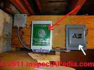
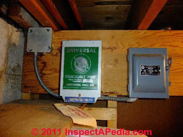
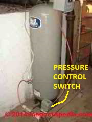
Illustration at above-left: orange extension cord wiring used to hook up the pump pressure control switch is an improper and unsafe electrical installation.
E.g.
- Abnormally-low pump circuit current draw:
a water pump that is running in a dry well will draw lower than normal current. - Abnormally-high pump circuit draw:
a pump running against unusual resistance (blocked outlet) may draw higher than normal current, as would a pump with a binding impeller or rotor or a bad bearing. If you could see the pump operating (which you can't under water very easily) you might see an abnormal temperature rise too. - Abnormal resistance
on pump circuit wires (with POWER OFF so we don't get fried) an indicate a shorted or grounded wire (zero or abnormally low resistance) or an open circuit (broken wire, high or infinite resistance)
So we could argue that a pump running against a waterlogged pressure tank might see higher than normal pressure but I doubt it. A water logged pressure tank will quickly if not immediately reach cut-out pressure and turn off the pump (unless the pressure control switch is itself faulty and not sensing that the tank is up to pressure).
Anyway it's easy enough to check for a waterlogged tank, as we discuss in this article series.
I think I'd pull the pump and check for binding bearings, damaged impeller that's binding, and if those looked good I might take it to an electric motor repair shop for more expert testing.
Also see SINGLE PHASE PUMP SERVICE MANUAL [PDF] (2005) Goulds, ITT, Website: www.goulds.com available from the company or free as a download at InspectApedia for examples of resistance tests of well pump motors and wiring.
Well Pump Wiring Size vs Distance & Voltage
Check also that your well pump wiring has been properly sized for the distance from building to well pump (e.g. for a submersible pump in the well). This table is a general guideline for well pump wiring sizing.
Well Pump Wire Size vs Distance (typical) |
|||
| Distance to Pump | Pump Amps |
Typical Wire Size (AWG) | |
| 120VAC | 220VAC | ||
| up to 50 ft / 15m | 20A | 12 | 14 |
| 50 - 100 ft / 15 - 30m | 12 | 14 | |
| 100 - 150 ft / 30 - 45m | 10 | 12 | |
| 150-200 ft / 45 - 60m | 8 | 12 | |
| 200- 300 ft / 60 - 90m | 6 | 10 | |
| 2,500 ft / 760m | 15A | 400 kcmil | 3/0 |
Notes to the table above:
- Wire notes: copper wire only
- Source: JET PUMP FAQs [PDF] Home Depot Stores, retrieved 2020/02/18 original source: https://images.homedepot-static.com/catalog/pdfImages/de/de8304aa-64d4-47ec-b075-a0e25c0ff64a.pdf
- See also WATER PUMP CAPACITIES TYPES RATES GPM
- See also DEEP WELL PUMP WIRE SIZE TABLE [PDF] Tuhorse, retrieved 2021/11/25 original source: https://www.tuhorse.us/drop-wire-selection-and-combining/
- For longer pump wire runs see SE CABLE & WIRE SIZES FOR LONG RUNS
- Watch out: the engineering work and derivation of the table above is derived from the sources listed below including manufacturer's tables and online voltage drop calculators but may not be correct for your specific installation. Check with your engineer or electrician.
Reader follow-up: successful well pump diagnosis traced to damaged wiring
 I've got this thing working. I went to go on vacation the last couple of days but had issues so I had to come home.
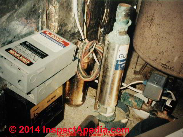
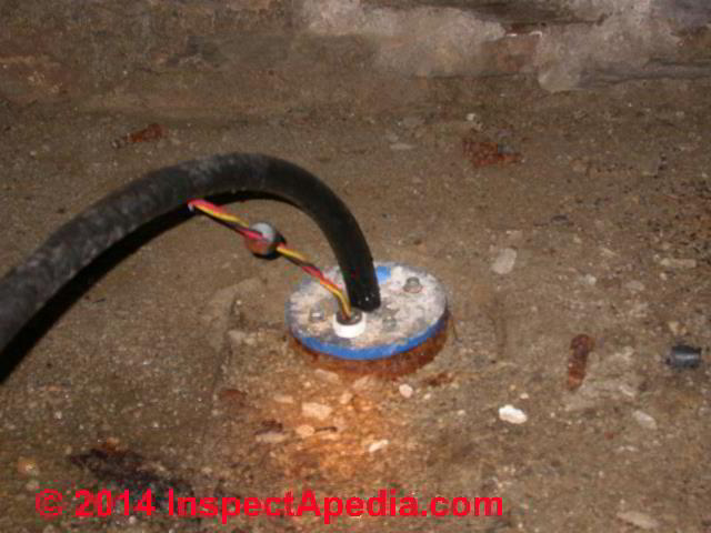
Image at left, not from Joe's home, illustrates un-protected 240V wiring entering the well casing at the casing top of a water well located in a building basement.
I spent all day with it, watching it, listening to it. Here is what I found:
I was showing 238V at the cut off box at the control box. when the pump kicked on, I was loosing one leg and this was tripping the double pole breaker
. I tested this theory (I actually seen the leg go off with the meter) by taking my generator and hooking the 230V side up to the pump. I have a 7000 watt generator, so there was no issue running the pump. It took about 5 minutes to fill the 120 gallon tank.
It took forever [for the water tank pressure] to get past 25 psi, but once it hit 30 psi it took about 2 minutes for it to reach the cut off pressure of 68 psi (my pump and tank are quite a ways from my house and I adjusted the pressure).
I had my wife and kids take showers, run the washing machine, and even used the sprinkler in the yard for a couple of hours and watched the pressure gauge and everything worked as normal.
With that being said, my power wire from the breaker box to the well is buried underground. I dug it up today and found a burned spot in the insulation. I cut the insulation back and found that the leg I was loosing when the pump came on was damaged.
I guess there was a nick in the wire when I buried it and didn't notice it. When the pump was not running, there was no current being pulled even though the voltage was still there.
When current started passing through the wire, there was enough missing insulation to trip the breaker - like a ground fault on a 480V system.
I am an industrial electrician and I'm very familiar with 480V-2300V systems. I wasn't sure in my original post if I was seeing an issue with the air pressure in the tank or something along those lines.
Final fix: repaired bad wire going to the pump control box.
Well Pump Wiring & Electrical Circuit Diagnostic Table |
||
|---|---|---|
Pump Trouble Cause Pump Won't Start |
Diagnostic Procedure | Repair Procedure |
| Blown fuse, tripped breaker | Replace fuse or breaker - does the pump run and keep running normally? | Be sure proper breaker or fuse size in ampacity is installed If breakers keep tripping test for shorted pump motor or pump wiring. |
| Low voltage to the pump | Check with VOM at the pressure control switch or at the pump wiring | Be sure the proper size of wire is used for the ampacity and length of circuit; Test for low voltage to the building. |
| Loose or broken pump wire | Check wiring against the pump installation manual diagram, check all connections for tightness, shorts, burns, damage A loose wire can cause intermittent pump or other electrical device failures as well as a hard failure that means no power or blown fuses. |
Rewire or repair or replace wiring See pump wiring tests in this article |
| Burned out pump motor | Check that the pump pressure control switch is trying to turn on the pump and that there is voltage at the pump wiring | Repair or replace the pump motor |
| Bad pump pressure control switch | Check the switch contacts for burning or wear | Adjust or replace the pressure control switch. Temporary emergency repair by cleaning the switch contacts may be possible. |
| Bad pump pressure control switch | Check the tubing connecting the pressure switch to the pump housing for clogging | Clean or replace the tubing and be sure the connections are not leaky - an air leak will prevent the switch from sensing pressure properly |
| Bad pump impeller or impeller seal leak | Turn off electric power to pump, see if you can move the impeller or motor - if it won't turn it is jammed or damaged | A bad impeller can jam the pump, causing it to draw high current. Remove obstruction in impeller housing, inspect for and replace damaged impeller or frozen motor. |
| Bad pump motor starting capacitor | Use a VOM in ohms setting to check resistance across the capacitor. If the meter does not move (no current flows) the capacitor is "open". If there is zero resistance the capacitor is shorted. |
Replace the starting capacitor |
| Pump motor shorted out, jammed, burned up | Fuse blows or breaker trips as soon as the pump tries to turn on. If the external wiring is ok (no short circuits) the motor is shorted internally | Replace the pump motor |
...
Things to Check if the Pump Motor Starts but Overheats and Trips its Reset Button |
||
| See ELECTRIC MOTOR OVERLOAD RESET SWITCH for how to find and reset this button | ||
| Bad line voltage | Use a VOM to check the voltage level at the pressure control switch | If voltage is too low, check voltage at the electrical panel and check that the proper size wiring was used for the ampacity and length of run and that there are no partial shorts or damaged wires or connectors |
| Incorrect motor wiring | Check the actual electrical wiring against the motor wiring diagram or the installation manual for the equipment | Reconnect wiring properly |
| Motor is too hot due to surroundings - inadequate ventilation | Check the air temperature where the motor is located. If the air temperature is over 100 degF, the pump may be too hot and its thermal overload switch tripping because of the environment, not a pump problem. |
Install adequate ventilation, or if needed, shading, or relocate the motor/equipment to a cool location |
| Pump operates too long at low water pressure | If the well recovery rate is too poor and the pump is operating at low water pressure, possibly because a tailpiece is installed to prevent air injection and pump burn up, the pump may be overheating. | Install a valve on the water discharge line and reduce water flow to increase water pressure inside the pump itself. |
...
What to do if the well pump runs continuously or runs too often |
||
| If the Well Pump Motor Runs Too Often | If the pump runs too often the cause may be a control problem, water tank problem, piping problem, or a well problem. | See INTERMITTENT CYCLING WATER PUMPS if the pump runs at odd times for no apparent reason. See WATER PUMP SHORT CYCLING CAUSES if the pump is turning on and off too frequently. |
| If the Well Pump Motor Keeps Running & Won't Stop | If the pump won't turn off the cause may be a damaged pump control, a plumbing or fixture leak, or a well problem. | Watch out: If the pump motor won't shut off you should turn off electrical power to the pump to avoid damaging it, then diagnose the problem. |
Notes: to the tables above
Some of the well pump troubleshooting suggestions in this list can be found at the Betta-Flo Jet Pump Installation Manual from the National Pump Co. Page top illustration courtesy of Carson Dunlop Associates, a Toronto home inspection, education & report writing tool company [ carsondunlop.com ].
Submersible Pump Wiring Diagrams & Connections
 On 2018-08-19 by Greg Rhymer - wiring connections when installing a four-wire submersible well pump
Hi, I am replacing my submersible well pump this new one is listed as (single phase 230v) with four(4) wires
two (2) are hot leads
one (1) is a ground
the last one (1) connects the capacitor motor.
Now is where my confusion begins
I only have three (3) wires at the well head and that continues through out the remainder of my system being the breaker shut off and the pressure switch. would I connect the capacitor to the common?
Since I will already need to connect the two (2) hot leads together.
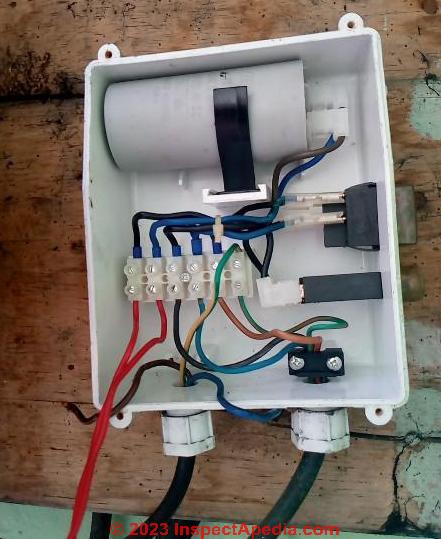
[Click to enlarge any image]
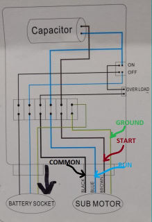
I have provided a picture of the inside cover of control box diagram.
On 2018-08-19 by (mod) - wiring diagram of a a 4-wire pump circuit
Greg, I'll be glad to research this further as from your question and image I'm not confident I can give a correct answer right-off.
What are the brand and model of the new pump?
What are the brand and model of the old pump?
Do we have a wiring diagram from the original submersible? Or the old control box?
Meanwhile, I have marked the identity of the wires in your wiring diagram.
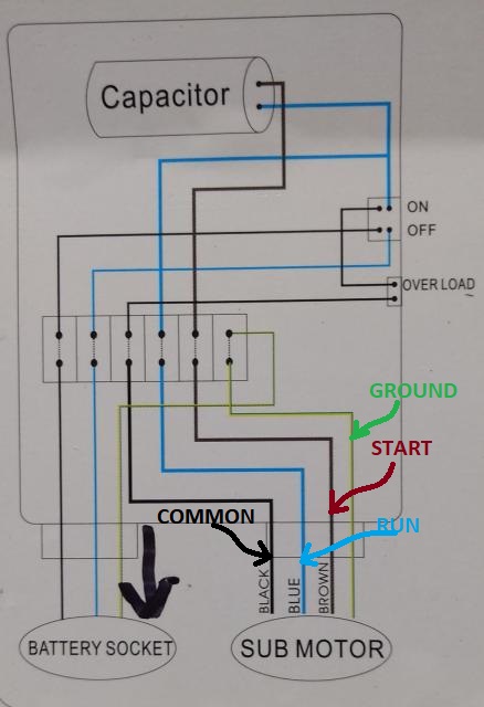
Typical 3 or 4-wire submersible pump control box wiring diagram

These 4-wire well pump wiring connections are typical for a single-phase submersible pump.
- GREEN = ground
- BLUE = run - this will be one of the two Line In power wires
- BROWN or RED = start wire between motor starting capacitor and motor S terminal as shown above
- BLACK = common - this will be the second of two Line In power wires
In the schematic above the orange wire connects the motor start relay CAP (Capacitor) terminal to the motor's Start/Run capacitor itself.
You will see that
- GREEN or safety ground connects to the circuit ground and typically to a control box ground terminal and a motor chassis ground terminal
- BLUE or "run"wire connects from the On-Off switch or relay to a capacitor R terminal and also to the motor's R or run terminal.
- BROWN or "start" wire connects from the S terminal on the capacitor to the S terminal on the motor
- BLACK or common connects from the on-off switch, often through an overload switch and on to the pump motor's C or common terminal
Notice that in a 3-wire well pump there is no white wire or neutral wire being used in this installation, even if the white neutral is present in your electrical box.
Power flows as follows:
Watch out: I cannot advise you to connect your pump to this control before we know more, as a short circuit could kill you.
? You have not told me if your pump is a 120V or a 240V motor, ditto for the control.
? You have not told me if there is one start/run capacitor or separate individual run and start capacitors
Typical 2-wire 240V Well Pump Wiring Connections

A 2-wire 240V well pump may have the following wires present and connected as given at the control box:
Notice in our two-wire pump wiring installation schematic above that both L1 and L2 "hot" wires may be black in color or one may be black, the other red.
- L1 - Line 1 from power source - black wire
- L2 - Line 2 from power source - black or red wire
- G - Ground from electrical system & ground to well pump circuit - green wire
- M1 - Motor 1 to pump motor - black or red wire
- M2 - Motor 2 to pump motor - black or red wire
Below is an example of wiring a 2-wire 230V Sta-Rite s724 well pump; note that this pump can be switched to run at 115V but is factory-set to 230V.

Details for this well pump are
at STA-RITE SSJ-SERIES VERTICAL JET PUMP INSTRUCTION MANUAL [PDF] S724-series jet pumps (2013, revised 2015)
Typical 3-wire 240V Well Pump Wiring Connections
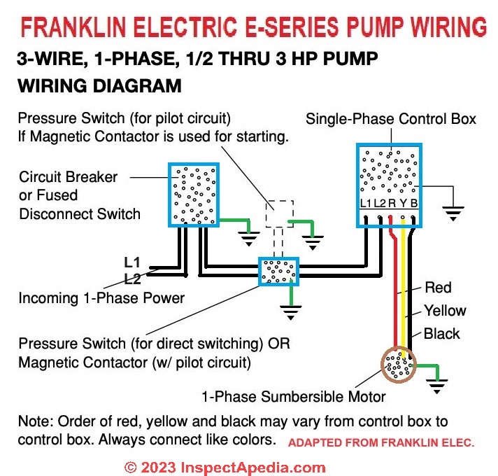
[Click to enlarge any image]
A 3-wire pump control box may actually have 6 physical wires present as follows:
Inputs:
- Line 1 - L1 - power in from pressure control switch, possibly through an overload or pump protection switch
- Line 2 - L2 - power in from pressure control switch, also possibly through an overload or pump protection switch
Outputs
- Red - pump run
- Black - pump common
- Yellow (or blue) pump start circuit
- Green - ground - earth
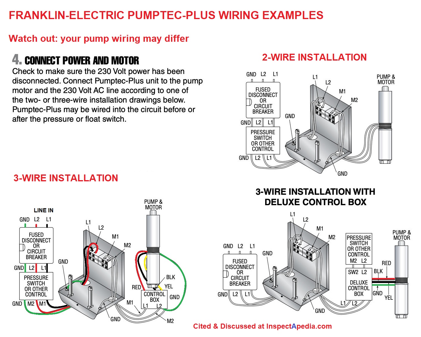
Above: Example wiring details using the Franklin Electric Pumptec-Plus pump controller - citation and manual links provided below. [Click to enlarge any image]
Watch out: your pump wiring requirements may differ: consult the IO manual for your pump and pump controller.
Well Pump Wiring Guides, Manuals References
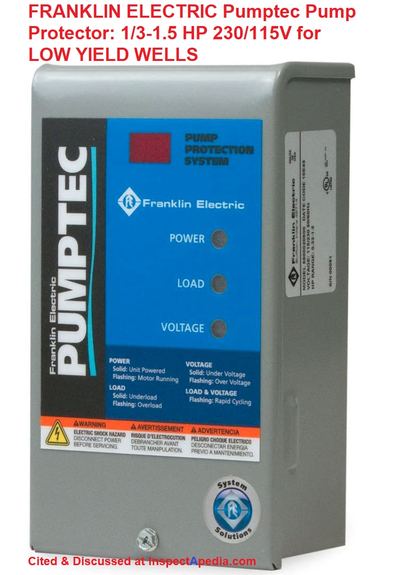 Illustration: Franklin Electric provides this Pumptec Control Box # 5800020610 that includes a pump protection circuit that prevents the pump from running dry: particularly suitable for low-yield wells. The control will stop the pump in low water conditions.
- Franklin Electric, 4" ENVIRONMENTAL E-SERIES PUMPS OWNERS MANUAL [PDF] Franklin Electric, 400 E. Spring St., Bluffton, IN 46714 USA Tel: 260-824-2900 Web: https://franklinwater.com/ retrieved 2021/06/25, original source: https://franklinwater.com/media/110586/106259101_E_Series_06-12_WEB.pdf
- Franklin Electric, PUMPTEC CONTROL BOX & PUMP PROTECTION DEVICE IO MANUAL [PDF] Franklin Electric, 400 E. Spring St., Bluffton, IN 46714 USA Tel: 260-824-2900 Web: www.franklin-electric.com
- Franklin Electric, PUMPTEC-PLUS PUMP CONTROL & PROTECTION SYSTEM INSTALLATION GUIDE [PDF] Franklin Electric, op. cit.,
- Franklin Electric PUMPTEC QD CONTROL BOX INSTALLATION MANUAL [PDF] Franklin Electric, op. cit., retrieved 2021/06/25, original source: https://franklinwater.com/media/180820/qd_pumptec_manual-225559101_m1551-.pdf
Excerpt: The QD Pumptec protects submersible pumping systems and is designed speci cally for use with Franklin Electric’s QD Relay Control Boxes and Franklin 230 V three-wire motors. The QD Pumptec microcontroller continuously monitors line voltage and motor current to protect against over voltage, under voltage and dry well conditions.
Dry well conditions are detected when the motor load drops below a factory preset (or eld calibrated) level for more than three seconds. When a dry well condition is detected, the unit will automatically restart after a selectable timeout period ranging from 2 to 240 minutes. Under and over voltage conditions will shut the unit off for two minutes and then automatically restart.
The QD Pumptec allows the user to choose the standard factory calibration for underload or to calibrate to a particular system. The user may select a reset time between 2 and 240 minutes. Note: Although the QD Pumptec may detect a deadhead condition, it is not guaranteed. Not all pumps unload under deadhead conditions. - Pumptrol® PRESSURE SWITCH ADJUSTMENT, [PDF] Square D, Schneider Electric Corporation, 8001 Knightdale Blvd., Knightdale< NC 27545 1-888-778-2733 - Square D Technical Library, web search 07/24/2010 original source: http://ecatalog.squared.com/techlib/docdetail.cfm?oid=09008926800a93be
- 9013 Pumptrol® COMMERCIAL PRESSURE SWITCHES Type F and 9013 Commercial Pressure Switches Type G, Catalog, [PDF] SquareD, Schneider Electric Industries SAS, Schneider Electric Industries SAS, web search 02/23/2011, original source:
http://ecatalog.squared.com/pubs/Machine Control/
Pressure-Float-Vacuum Switches/Pressure Switches-Water and Air/9013CT9701.pdf
- Class 9013 Square D Commercial Pressure Switches: WATER PUMP PRESSURE CONTROL SWITCH CLASS 9013, Type F, G, Manual, [PDF] Square D Company, 8001 Highway 64 East, Knightdale, NC 27545-9023, USA, (919) 266-3671, www.squared.com,
web search 02/24/2011, original source: stevenengineering.com/tech_support/PDFs/45COM.pdf. Quoting:
The Type FSG, FYG, FRG - PUMPTROL® Water Pump Pressure Switches are used to control Water Pump Pressure Switches are used to control
electrically driven water pumps and have the following features:- The Type FSG is the standard water pump switch, suitable for all types of pumps: jets, submersible,
reciprocating, etc. - The Type FYG is designed to meet higher horsepower and pressure requirements.
- The Type FRG is reverse acting: the contacts open on falling pressure.
All are diaphragm actuated. - The Type G - PUMPTROL® Commercial/Light Industrial Pressure Switch is used to control electrically
driven water pumps and air compressors.
It has higher electrical ratings for direct control of motors in pump and compressor applications. The Type G switch is diaphragm actuated and has contacts that open on rising pressure.
- The Type FSG is the standard water pump switch, suitable for all types of pumps: jets, submersible,
- Water Pumps Direct HOW to INSTALL and WIRE a WeLL PUMP - Welll Pump Installation Guide [PDF] by Jim O. "Water Pump Expert" at this page, Water Pumps Direct, Tel: 888-455-4681, Web: waterpumpsdirect.com - retrieved 2023/09/14, original source: waterpumpsdirect.com/stories/1852-Well-Pump-Installation-Guide.html
Causes Of & Cures For Broken Submersible Well pump Wiring
This discussion has moved to WATER PUMP WIRING DAMAGE
Reader Comments, Questions & Answers About The Article Above
Below you will find questions and answers previously posted on this page at its page bottom reader comment box.
Reader Q&A - also see RECOMMENDED ARTICLES & FAQs
On 2023-04-20 by InspectApedia Editor - an experienced electrician or one with any sense would have labeled each wire in the panel individually
@SAM,
I wanted to add that if the breakers in your old electrical panel were labeled, then when the new panel was to be installed, an experienced electrician or one with any sense would have labeled each wire in the panel individually so that when the wires were connected to new breakers in the new panel, their connection position and breaker would be known and thus could be labeled on the panel's list of breakers and their use.
On 2023-04-19 by InspectApedia Publisher
@SAM,
If it's a 220VAC pump and you're only 1 of the two legs then yes you can damage the pump. You need to turn it off.
It's a mistake to ruin your pump because you don't know which breaker turns it off.
Simply switch off each breaker or 220V breaker pair one by one until the pump stops.
Then you will know which breaker operates the pump.
On 2023-04-19 by SAM
@InspectApedia Editor ,
He won't tell me why he did it, but as I said he didn't connect the red wire in the panel, he just placed a marret on it. So the darn pump is always showing hot. The breaker even turned off, it shows that it's connected.
Pump is not able to work as it doesn't have enough power.
I am asking if this would break the pump.
The well guy refused to come out until the panel is labeled and the pump can be turned off at the panel, (I don't blame him)
On 2023-04-19 by InspectApedia Editor - If NO circuit breakers will turn off your pump then something is certainly wrong and unsafe
@SAM,
If NO circuit breakers will turn off your pump then something is certainly wrong and unsafe.
And if the pump never stops, there's risk of damage to the pump motor or impeller.
If you turn off the MAIN breaker the pump should stop. If not then it's getting power from some other source that needs to be found and turned off.
Let me know what you find./see/do
On 2023-04-19 by SAM
Hi we just had a new electrical panel installed. The electrician marretted the red wire off inside the panel for the well pump, he hasn't said why. I couldn't get it to turn off with the any of the breakers, so I messaged him to ask why.
What I would like to know is would this wreck the well pump?
Thank you
On 2022-11-08 by InspectApedia (Editor)
@Bestman Yima,
What you describe about which wires are alive at your water pump control is not necessarily a problem. For example a 220 volt pump will have two hot wires feeding the motor.
Watch out: there's live voltage in that control and if you touch something you could be shocked or killed.
If you post a photo of the identification data tag or model number for your water pump control we can be sure to point you to the proper instructions for it.
On 2022-11-08 by Bestman Yima
Am having issue on with my calendar control box. I tried to pump water but it refused to pump when i open the box, i then discover that the current is running in boy negative and positive wire.
On 2022-11-04 by Andrew W
@InspectApedia-911
Many thanks for your advice!
On 2022-11-04 by InspectApedia-911 (mod)
@Andrew W,
You measure the run current if you're interested in the current drawn as the pump is running,
You'd measure the start current if you're diagnosing a motor start problem and want to see the current drawn as the motor is starting.
See detailed procedures for measuring amps at
AMPS MEASUREMENT METHODS
On 2022-11-04 by Andrew W
I would like to measure the current on my 3 wire pump , which has a rated current of 6 - 6.5amps, using a clamp meter. Which specific wire(s) on the pump do I measure, ie., the common, the start and/or the run, to get the measurement? Any advice would be most appreciated.
On 2022-09-03 by InspectApedia-911 (mod) - How do I test with multimeter?
@Talltony1959,
In the article above, in the section titled
Well Pump Wiring Guides, Manuals References
you will find live links to these pages that give detailed motor test instructions
DMM DIGITAL MULTIMETER HOW TO USE
ELECTRIC MOTOR DIAGNOSTIC GUIDE - home
ELECTRIC MOTOR TESTS
Watch out: if you're not familiar with safe and proper electrical wiring and testing you could be shocked or killed.
Also take a look at
DMMs VOMs SAFE USE OF
On 2022-09-03 by Talltony1959
2 wire with ground well pump running but low pressure. How do I test with multimeter?
On 2022-07-15 by InspectApedia-911 (mod) - pump runs but delivered insufficient water
@Gondo,
Could your water source have run out?
On 2022-07-14 by Gondo
I just connected my surbmesible pump and run it by solar. The pump runs but delivered insufficient water. After about 30 minutes it stops and the controller shows two possibilities; cable not connected well or impeller is stuck. But the cable is connected well. What may be the cause.
On 2022-07-11 by InspectApedia-911 (mod) - How long does the red start wire operate before switching to the black run wire?
@Dave Lowthorp,
I think you're asking about the start capacitor on a pump motor. The start capacitor is taken out of a circuit usually by centrifugal switch in the pump motor once the pump gets close to its run speed which on a modern motor would probably be 3450 RPM. That's just milliseconds.
On 2022-07-10 by Dave Lowthorp
How long does the red start wire operate before switching to the black run wire? (2 HP, 230V, 1 PHASE Submersible Water Pump at 200')
...
Continue reading at WATER PUMP WIRING DAMAGE or select a topic from the closely-related articles below, or see the complete ARTICLE INDEX.
Or see WELL PUMP WIRING REPAIR FAQs - questions & answers posted originally at this article
Or see these
Recommended Articles
- DO IT YOURSELF ELECTRICAL WORK - warnings
- DMM DIGITAL MULTIMETER HOW TO USE
- ELECTRIC MOTOR DIAGNOSTIC GUIDE - home
- ELECTRIC MOTOR TESTS
- WATER PUMP DIAGNOSTIC TABLE
- WATER PUMP ELECTRICAL SWITCHES
- WATER PRESSURE CONTROL SWITCH ADJUSTMENTS
- WATER PUMP PROTECTION SWITCH
- WATER PUMP RELAY SWITCH
- WATER PUMP & TANK I&O & REPAIR MANUALS - complete set of well / water pump installation, wiring & repair manuals
- WATER PUMP SHORT CYCLING DIAGNOSIS TABLE - table format.
- WATER PUMP WIRING DAMAGE
- WATER PUMP WIRING REPAIR
- WATER PUMP PRESSURE SWITCH MANUALS
Suggested citation for this web page
WATER PUMP WIRING REPAIR at InspectApedia.com - online encyclopedia of building & environmental inspection, testing, diagnosis, repair, & problem prevention advice.
Or see this
INDEX to RELATED ARTICLES: ARTICLE INDEX to WATER SUPPLY, PUMPS TANKS WELLS
Or use the SEARCH BOX found below to Ask a Question or Search InspectApedia
Ask a Question or Search InspectApedia
Try the search box just below, or if you prefer, post a question or comment in the Comments box below and we will respond promptly.
Search the InspectApedia website
Note: appearance of your Comment below may be delayed: if your comment contains an image, photograph, web link, or text that looks to the software as if it might be a web link, your posting will appear after it has been approved by a moderator. Apologies for the delay.
Only one image can be added per comment but you can post as many comments, and therefore images, as you like.
You will not receive a notification when a response to your question has been posted.
Please bookmark this page to make it easy for you to check back for our response.
Our Comment Box is provided by Countable Web Productions countable.ca
Citations & References
In addition to any citations in the article above, a full list is available on request.
- In addition to citations & references found in this article, see the research citations given at the end of the related articles found at our suggested
CONTINUE READING or RECOMMENDED ARTICLES.
- Carson, Dunlop & Associates Ltd., 120 Carlton Street Suite 407, Toronto ON M5A 4K2. Tel: (416) 964-9415 1-800-268-7070 Email: info@carsondunlop.com. Alan Carson is a past president of ASHI, the American Society of Home Inspectors.
Thanks to Alan Carson and Bob Dunlop, for permission for InspectAPedia to use text excerpts from The HOME REFERENCE BOOK - the Encyclopedia of Homes and to use illustrations from The ILLUSTRATED HOME .
Carson Dunlop Associates provides extensive home inspection education and report writing material. In gratitude we provide links to tsome Carson Dunlop Associates products and services.
 | HOME | ABOUT | ASK a QUESTION | CONTACT | CONTENT USE POLICY | DESCRIPTION | POLICIES | PRIVACY | |
| © 2024 - 1985 Publisher InspectApedia.com - Daniel Friedman | |||||||||