
InspectAPedia® FREE Encyclopedia of Building & Environmental Construction, Diagnosis, Maintenance & Repair |
Question? Just ask us! InspectAPedia
|
 Wiring a Honeywell Room Thermostat
Honeywell or Resideo Thermostat Wiring Connection Tables &
Hook-up Procedures
- POST a QUESTION or COMMENT about heating, air conditioning, and heat pump thermostat installation and wiring
Thermostat wiring details & connections for nearly all types of Honeywell room thermostats used to control residential heating or air conditioning systems.
This article gives a table showing the proper wire connections for Honeywell brand wall or room thermostats used to control heating or air conditioning equipment.
Room thermostat installation & wiring guide: this article series explains the basics of wiring connections at the thermostat for heating, heat pump, or air conditioning systems.
Our page top sketch, courtesy of Honeywell Controls, illustrates the wiring diagram for a traditional Honeywell T87F thermostat used for 2-wire single pole single throw control of heating only in a typical gas-fired heating system.
InspectAPedia tolerates no conflicts of interest. We have no relationship with advertisers, products, or services discussed at this website.
Honeywell Thermostat Wiring Guide
- Contact Honeywell / Resideo Technologies, Inc., for Assistance in wiring or for spare parts for thermostats:
Resideo Technologies, Inc., 1985 Douglas Drive North, Golden Valley, MN 55422 USA Tel: 1-800-468-1502
Note: In 2018 Honeywell announced that Resideo would be the corporate name of the Honeywell Homes product portfolio and ADI global distribution businesses when they became a stand-alone, publicly traded company following completion of a spin that was expected by the end of 2018.
Resideo help for thermostat wiring: https://www.resideo.com/us/en/thermostat-wiring-compatibility/
Honeywell International Inc. now Resideo Inc., 1985 Douglas Drive North Golden Valley, MN 55422 USA, Telephone: 1-800-0468-1502, or
Website: http://yourhome.honeywell.com
Honeywell thermostats, wiring connections, instructions, diagrams
- HONEYWELL SERIES 20 WALL THERMOSTAT WIRING
- HONEYWELL 5-2 DAY PROGRAMMABLE THERMOSTAT - RTH2300B1012 WIRING
- HONEYWELL FAN COIL THERMOSTAT T6169 MANUAL [PDF] (2001) retrieved 2020/01/16 original source: https://customer.honeywell.com/resources/Techlit/TechLitDocuments/95C-00000s/95C-10679.pdf
Excerpt: The T6169 thermostats control line voltage valves an/or blower motors on Fan Coil units in manual or automatic changeover, cooling, heating or cooling/heating systems.
These thermostats feature single fan an/or system manual switches.
Honeywell T87 Type & Other Thermostat Installation & Operation Manuals
- HONEYWELL T87-F type 2-WIRE WALL THERMOSTAT WIRING
- HONEYWELL T87-F type 3-WIRE WALL THERMOSTAT WIRING
- HONEYWELL T87 WALL THERMOSTAT WIRING DIAGRAMS, OTHER - Honeywell Wall T87-F type Thermostats for sketches and drawings of Honeywell thermostat wiring hookups.
Older Honeywell Thermostat Wiring Diagrams
- 2-WIRE GAS HEAT Honeywell Thermostat Wiring Diagram
- 2-WIRE OIL HEAT Honeywell Thermostat Wiring Diagram
- 3-WIRE HIGH LIMIT Honeywell T87F Thermostat wiring diagram
- 3-WIRE SPDT Honeywell T87F Thermostat wiring diagram
- 4-WIRE Honeywell RTH2300 Programmable Thermostat Wiring diagrams
Honeywell Thermostat Installation & Wiring Manuals
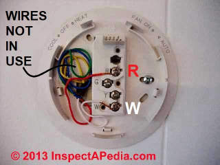
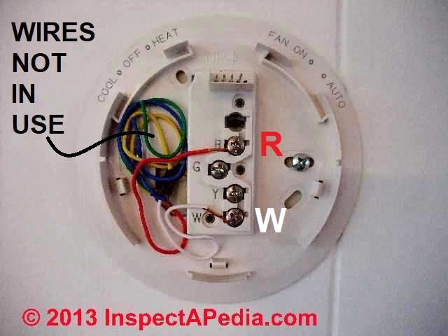
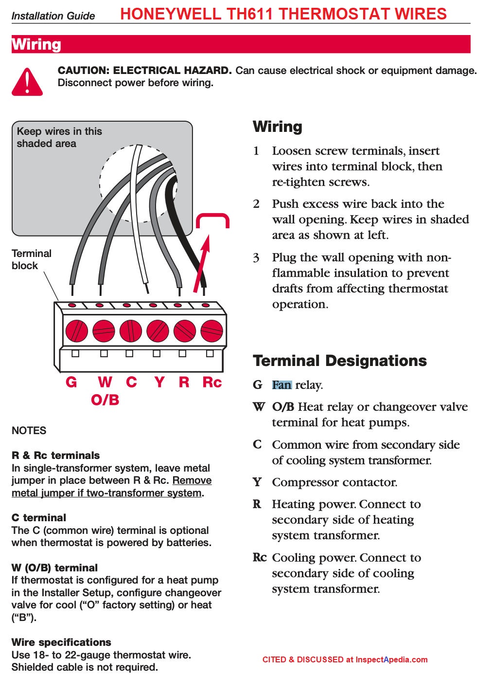 Illustration: wiring terminals for the Honeywell TH611 Thermostat -
[Click to enlarge any image]
- HONEYWELL CHRONOTHERM THERMOSTAT 1950 [PDF]
- HONEYWELL CT-87 THERMOSTAT USERS MANUAL [PDF], retrieved 2018/08/02, original source: https://customer.honeywell.com/resources/techlit/TechLitDocuments/69-0000s/69-1919EFS.pdf
- HONEYWELL CT87N / CT87K ROUND THERMOSTAT OWNERS MANUAL [PDF] Honeywell International, Inc., 1985 Douglas Drive North, Golden Valley MN, 55422 or in Canada: 35 Dynamic Drive, Toronto, Ontario M1V 4Z9, Canada, Website: http://yourhome.honeywell.com retrieved 2016/03/06.
- HONEYWELL CT87N / CT87K THERMOSTAT OWNER'S MANUAL [PDF] 69-1959EFS—02
- HONEYWELL CT87 INSTALLATION QUICK GUIDE [PDF]
- HONEYWELL CT97N Easy-to-See™ THERMOSTAT OWNER'S MANUAL [PDF] 69-1919EFS—06
- HONEYWELL CT87A,B,J Round® Thermostat Low Voltage (15 to 30 VAC) Thermostat and Mounting Hardware Installation Instructions (2002) [PDF]
- HONEYWELL FocusPRO TH6110D PROGRAMMABLE THERMOSTAT INSTALLATION GUIDE [PDF] (2005) [Illustrated just above] for the Honeywell TH6110D & Honeywell TH6220D thermostats.
Excerpt:
This thermostat provides electronic control of 24 VAC single-stage heating and cooling systems, or 750 mV heating systems. - HONEYWELL FocusPRO TH6110D / TH6220D OPERATING MANUAL [PDF] Programmable Thermostat User's Guide
- HONEYWELL Lyric Round™ WI-FI THERMOSTAT INSTALLATION GUIDE [PDF] Honeywell Controls, retrieved k2020/01/16 original source: https://forwardthinking.honeywellhome.com/related_links/thermostats/lyric/Professional_Installation_Guide.pdf
- HONEYWELL T6 Pro PROGRAMMABLE THERMOSTAT INSTALLATION INSTRUCTIONS [PDF] Honeywell TH6210U2001 thermostat manual
- HONEYWELL T87F Thermostat PRODUCT DATA SHEET & CIRCUIT DIAGRAMS [PDF] (2002)
- HONEYWELL T8775C1005/U THERMOSTAT INSTALLATION & WIRING MANUAL [PDF] Digital Round T8775 retrieved 2018/10/07, original source: https://customer.honeywell.com/resources/Techlit/TechLitDocuments/69-0000s/69-1679ES.pdf
The manual above also applies to the Honeywell T8775A1009/U and to the T8775A1017/U
HONEYWELL TB7100A1000 MultiPRO™ Multispeed and Multipurpose Thermostat INSTALLATION & WIRING MANUAL [PDF] retrieved 2018/10/07, original source: https://customer.honeywell.com/resources/techlit/TechLitDocuments/62-0000s/62-0273.pdf
- HONEYWELL Wi-FI Thermostat 9000 INSTALLATION GUIDE [PDF], Honeywell Controls, retrieved k2020/01/16 original source: https://customer.honeywell.com/resources/Techlit/TechLitDocuments/69-0000s/69-2815EFS.pdf
More Honeywell Thermostat Types, Instructions, Manuals
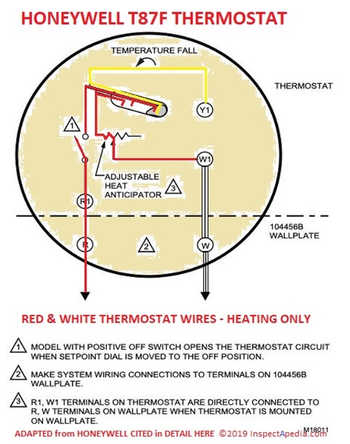
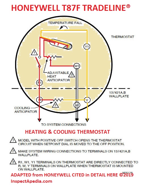
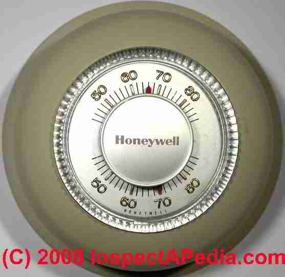
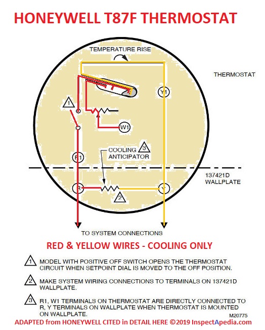
Above & Below: Honeywell T87F Thermostats in three versions: Heating Only, Heating & Cooling, & below, Cooling Only
- HONEYWELL DT 92E THERMOSTAT SPECIFICATIONS [PDF] t that describes the DT92E thermostat Standby and other features
- HONEYWELL DT 92E THERMOSTAT INSTALLATION MANUAL [PDF] instructions including how to enter the DT92 "Installer Mode" when needed.
- HONEYWELL RTH3100C THERMOSTAT INSTALLATION & WIRING [PDF] notes, wiring connections & copy of the RTH3100C Thermostat Manual
- HONEYWELL RTH4330B THERMOSTAT MANUAL [PDF] Programmable thermostat instructions
- HONEYWELL RTH6350 / RTH 6450 THERMOSTAT INSTALLATION & WIRING also support for the Honeywell RET93E / RET95E series thermostats
- HONEYWELL T8775 THERMOSTAT USERS MANUAL [PDF] retrieved 2018/08/02, original source: https://customer.honeywell.com/resources/techlit/TechLitDocuments/69-0000s/69-1679EF.pdf
- HONEYWELL TH9320WF5003/U WiFi 9000 Series Color Touchscreen Thermostat instructions, wiring connections, setup guide, copy of the TH9320WF5003/U Manuals [PDF]
How to Wire the Three-Wire Honeywell Wall Series 20 Thermostat, CT-87, & T8775X
Honeywell Wall Series 20 Thermostat, CT-87, & T8775X Wire Connections(3 wires found in-use at the wall thermostat) |
||
| Thermostat Terminal ID |
Wire Color | Three-Wire Heat Thermostat Hookup Comments |
| Red | Red wire coming to the thermostat from the heater. See Note 1 in the table above. | |
| Blue wire |
For Honeywell Wall T87-F type Thermostats Connect the blue wire coming to the thermostat from the heater or air conditioner | |
| White wire | Watch out: [2] | |
Notes to the table above
1. Also see HONEYWELL THERMOSTAT WIRING DIAGRAMS - Honeywell Wall T87-F type Thermostats
2 Watch out: For Honeywell Wall Series 20 type Thermostats connect the white wire coming to the thermostat from the heater or air conditioner to the (Y) terminal, not the (W) terminal.
How to Wire the Honeywell the 5-2 Day Programmable Thermostat - RTH2300B1012
| Honeywell the 5-2 Day Programmable Thermostat - RTH2300B1012 alternative wiring Connections | ||
|---|---|---|
| Old thermostat wire label | Connects to RTH2300B Terminal | Comments |
| C, C1, X, B | nothing - not used | Note 1 |
| O, B, H | O/B | |
| Y, Y1, M | Y | Note 3 |
| R, RC, RH, 4, V | R | Note 2 |
| G, F, L | G | |
| W, W1, W2, H | W | Note 3 |
Notes to the table above
1. Do not use C, C1 or X wire. Do not use B wire if you already have O wire. Wrap bare end of wire with electrical tape.
2. This thermostat cannot be used if your old thermostat had [and used] any two of the following wires: R, RC, RH, 4 and V.
3. Place a jumper (piece of wire) between Y and W if you have a heat pump without auxiliary/back-up heat.
Wiring Instructions for Honeywell T87-F Thermostats & their Replacements
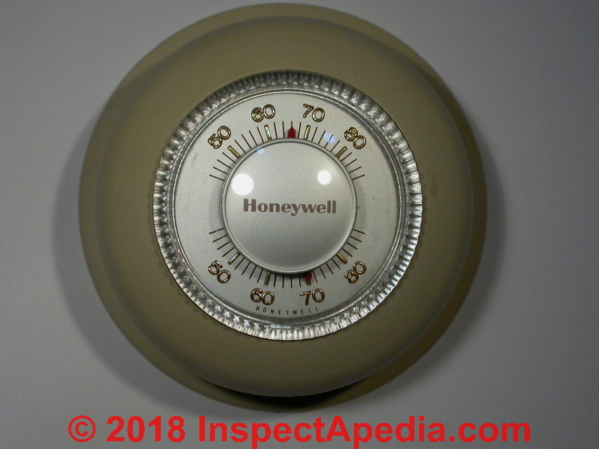
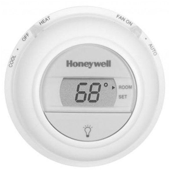
Shown here is the company's original traditional T87 round, non-programmable thermostat and its contemporary, digital replacement that will be wired identically: Honeywell's T8775C1005.
How to Wire a typical Two-Wire Honeywell T87-F type Wall Thermostat
Thermostat Wiring Connections for typical Two-Wire Honeywell T87-F type Wall Thermostats |
||
| Thermostat Terminal ID |
Wire Color | Two-Wire Heat Thermostat Hookup Comments |
| Red | Red wire coming to the thermostat from the heater. Connected to the R terminal in the room thermostat. See Note 1 in the table above. |
|
| White | White wire coming to the thermostat from the heater, connect to the W terminal in the thermostat. | |
Notes to the table above
(only 2 wires found in-use at the wall thermostat)
Honeywell thermostat T87F type models include the Super Tradeline T87F1959 (replaces the T26A1433 and T87C1252), T87F1867, T87F2816, T87F2824, T87F2873
These thermostat T87F models vary by the operating temperature range they support and a few other simple features such as the presence or absence of a thermometer. Functionally and for wiring they are similar.
1. The [Honeywell 5-2 Day Programmable Thermostat - RTH2300B1012] thermostat cannot be used if your old thermostat had [and used] any two of the following wires: R, RC, RH, 4 and V.[5]
2. Also see these other HONEYWELL T87 WALL THERMOSTAT WIRING DIAGRAMS
3. Some thermostats will be supplied with a jumper wire or clip between the thermostat RH and RC terminal and will not provide a simple R terminal (such as the 3M-22 Filtrete). Connect the red wire t
How to Wire the Three-Wire Honeywell Wall T87-F type Thermostat
Three-Wire Honeywell Wall T87-F type Thermostat Connections(3 wires found in-use at the wall thermostat) |
||
| Thermostat Terminal ID |
Wire Color | Three-Wire Heat Thermostat Hookup Comments |
(RH) |
Red | Red wire coming to the thermostat from the heater. See Note 1 in the table above. |
| Blue wire |
For Honeywell Wall T87-F type Thermostats Connect the blue wire coming to the thermostat from the heater or air conditioner | |
| White wire | Watch out: For Honeywell Wall T87-F type Thermostats connect the white wire coming to the thermostat from the heater or air conditioner to the (Y) terminal, not the (W) terminal. | |
Notes to the table above
Also see these other HONEYWELLT87 WALL THERMOSTAT WIRING DIAGRAMS - Honeywell Wall T87-F type Thermostats for sketches and drawings of Honeywell thermostat wiring hookups.
Wiring Details & Troubleshooting for the Honeywell 5-2 Day Programmable Thermostat - RTH2300B1012
Remember that ultimately a thermostat is simply an on-off switch, or provides several on-off functions. But with multiple zone heat, you should expect to provide a thermostat for each individual zone - or else they're not heating zones at all.
In a traditional hot water heating system that does not use the Azel i-Link controller, the first thermostat is wired directly to an aquastat that controls the first zone; the second two thermostats are wired to individual circulator relays (if individual circulator pumps are used) or to individual zone valves (if a single circulator runs the whole system).
Where zone valves are used, an end switch closes to turn on the circulator (a logical inclusive OR function with the other zone valves) when the zone valve opens to allow hot water to flow. That same principle is used when wiring the Azel i-Link Zone Switching Relay. And the company makes clear that their controller is compatible with standard thermostats:
ALL - controls are compatible with 2, 3 or 4 wire type thermostats. 24VAC output can be used to supply power to the thermostat. For thermostats requiring the 24VAC Common, simply connect C terminal from the thermostat to COM terminal on the 24VACoutput.[4]
First let's make sure you've identified your Honeywell thermostat model correctly.
Your [Honeywell thermostat] model number will begin with the letters, T, TH, RTH, C, or CT and is on the back of the thermostat.[5]
Honeywell RHT2300B - the number you gave, doesn't look right, but you probably meant RTH-2300-B. Calling Honeywell with the right product number (Tel: 800-468-1502) might produce better results. Honeywell has done a great job making installation and operations manuals available for their equipment, but you've got to search with the right product number.
Searching the Honeywell site for the corrected thermostat number delivers a single product that's probably yours, the 5-2 Day Programmable Thermostat - RTH2300B1012.
In fact this thermostat is widely sold including at Home Depot stores, and I've installed and used this very model myself to control an add-on hot water heating zone and Taco circulator in an older home. According to Honeywell, this thermostat is compatible with:
- Gas, oil or electric furnace
- Central air conditioner
- Millivolt system
- Central heating and cooling system
- Heat pump without auxiliary/backup heat. (This thermostat cannot be used on heat pumps with auxiliary heating or on multistage systems.)
For your model you want Honeywell document 69-2326ES - found at http://customer.honeywell.com/Honeywell/getliterature.axd?LiteratureID=69-2326ES.pdf - owners operation manual or
document 69-2327ES - for installation materials - found at
http://customer.honeywell.com/Honeywell/getliterature.axd?LiteratureID=69-2327ES.pdf
Here are details from that manual's instructions for wiring the Honeywell RTH-2300-B 5-2 Day Programmable Thermostat beginning with the inspection of the existing wires:
How to Correctly Identify the existing thermostat wires
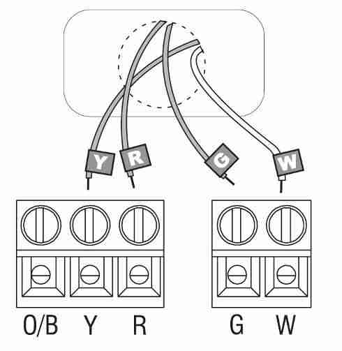
3. Identify and label each of the existing thermostat wires by using not the wire colors (someone could have made a wire color error and violated convention) but rather, identify each existing thermostat wire by noting the letter next to the old thermostat wiring block terminals where each wire was connected to a screw. Identify and label the wires that are connected as
- R (convention would be red wire)
- W (convention would be white wire)
- Y (convention would be yellow wire)
- G (convention would be green wire)
- C (convention would be "common" wire)
If any wires are not attached to your old thermostat or are attached to a terminal marked C or C1, they will not be connected to your new thermostat. Wrap the bare metal end of each of these wires with electrical tape, so it cannot touch and short other wires.
Watch out: since here we are focusing on connections, I am leaving out some important procedure and safety details like removing and taping each wire end to avoid shorting, etc. so be sure to consult the installation manual in detail.
On your new thermostat, the Honeywell the 5-2 Day Programmable Thermostat - RTH2300B1012, connect the wires you labeled as follows:
- Wire labeled R (convention would be red wire) is connected to the "R" terminal on the thermostat
- Wire labeled W (convention would be white wire) is connected to the "W" terminal on the thermostat
- Wire labeled Y (convention would be yellow wire) is connected to the "Y" terminal on the thermostat
- Wire labeled G (convention would be green wire) is connected to the "G" terminal on the thermostat
- C (convention would be "common" wire) - you won't use this on the new thermostat
Honeywell 5-2 Day Thermostat Wiring Table: If the wire labels from your old thermostat hookup don't match the above, Honeywell offers additional advice that we adapt in table form provided in detail
at HONEYWELL 5-2 DAY PROGRAMMABLE THERMOSTAT - RTH2300B1012 WIRING.
If the wire labels from your old thermostat hookup don't match the above, Honeywell offers additional advice that we adapt in table form:
| Honeywell the 5-2 Day Programmable Thermostat - RTH2300B1012 alternative Connections | ||
|---|---|---|
| Old thermostat wire label | Connects to RTH2300B Terminal | Comments |
| C, C1, X, B | nothing - not used | Note 1 |
| O, B, H | O/B | |
| Y, Y1, M | Y | Note 3 |
| R, RC, RH, 4, V | R | Note 2 |
| G, F, L | G | |
| W, W1, W2, H | W | Note 3 |
Notes to the table above
1. Do not use C, C1 or X wire. Do not use B wire if you already have O wire. Wrap bare end of wire with electrical tape.
2. This thermostat cannot be used if your old thermostat had [and used] any two of the following wires: R, RC, RH, 4 and V.
3. Place a jumper (piece of wire) between Y and W if you have a heat pump without auxiliary/back-up heat.
Here is a copy of the HONEYWELL RTH2300/RTH221 SERIES PROGRAMMABLE THERMOSTAT OWNERS MANUAL [PDF]
Other methods for identifying thermostat wires are at THERMOSTAT WIRING COLOR CODES and at THERMOSTAT WIRE TERMINAL ID CODES / FUNCTIONS.
Honeywell RTH3100C Thermostat Installation & Wiring
Below Honeywell shows the typical wiring connections or the RTH3100C thermostat.
Be sure that you label the wires before disconnecting them from the old thermostat, or if you are installing new equipment, identify the incoming wires from the equipment terminals and its manual.
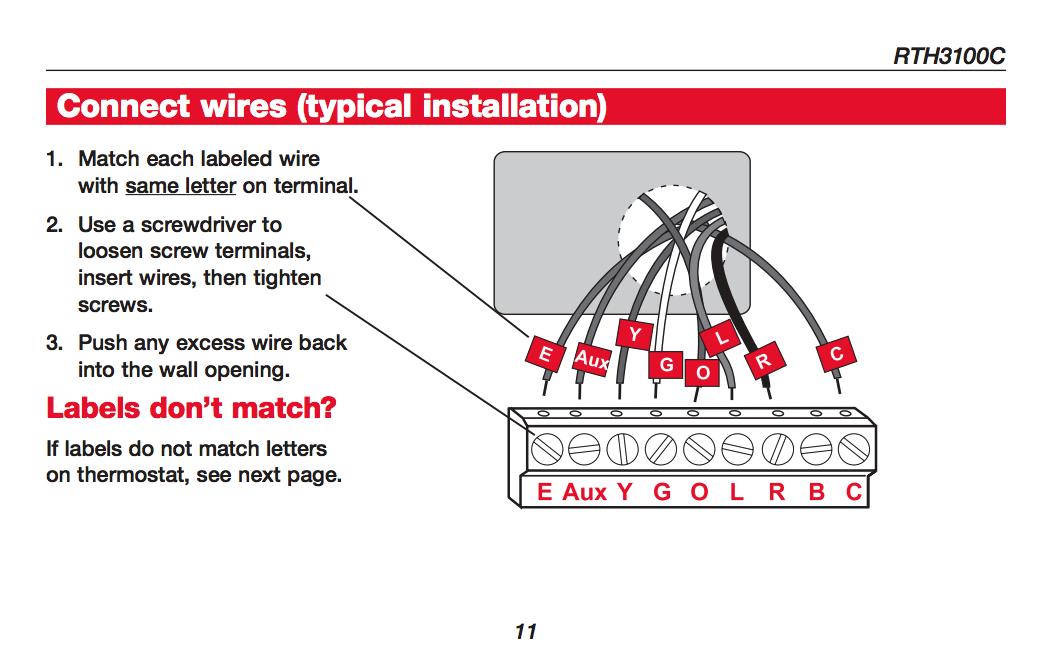
[Click to enlarge any image]
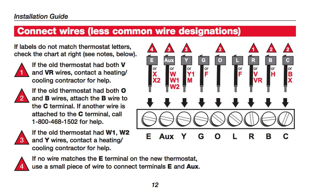
Below are alternative wiring connections for the Honeywell RTH3100C thermostat along with an explanation.
Below is the complete Honeywell RTH3100C thermostat installation manual in PDF format.
- HONEYWELL RTH3100C THERMOSTAT INSTALLATION & WIRING [PDF] manual,(2008) retrieved 2017/09/17, original source: https://customer.honeywell.com/ resources/ techlit/TechLitDocuments /69-0000s/69-1889EF.pdf
- Contact Honeywell for Assistance in wiring by Telephone: 1-800-0468-1502, or Website: http://yourhome.honeywell.com
Honeywell RTH6350/ RTH6450 & RET93E / RET95E Thermostat Installation & Wiring Guide
The Honeywell RTH6350 uses the following wire connections:
Basic RTH6350 / 6450 Wire Connections
- Green wire(G) to G terminal on the thermostat
- White wire (W) to the W terminal
- Yellow wire (Y) to the Y terminal
- Red wire (R) to the R terminal, with this note: remove the factory-installed jumper between R and RC IF you have both an R wire and an RC wire (that you should have identified and labeled from your old thermostat hookup).
Alternate RTH6350 / RTH6450 RET93E / RET95E Wire Connections
- C / X / B - do not connect - tape off bare wire ends
- Y2 wire to Y2 terminal on the thermostat wiring bus bar
- W2 wire to W2 terminal
- G or F wire to G terminal
- W or W1 or H wire to W terminal
- Y or Y1 or M wire to Y terminal
- Rh, 4 or V wire to R terminal, after removing factory-installed metal jumper between R and Rc
- Rc or R wire to Rc terminal, after removing factory-installed metal jumper between R and Rc
Watch out: if your wires do not match the above see several alternative wiring installation hookups on both of the thermostat wiring manuals given just below.
HONEYWELL RTH6350 / RTH6450 THERMOSTAT INSTALLATION GUIDE [PDF] retrieved 2017/12/26, original source: https://customer.honeywell.com/resources/techlit/TechLitDocuments/69-0000s/69-2416ES.pdf
HONEYWELL RTH6350 / RTH 6450 and RET93E / RET95E Series Thermostats INSTALLATION & OWNERS MANUAL [PDF] retrieved 2017/12/26, original source: https://customer.honeywell.com/resources/techlit/TechLitDocuments/33-00000s/33-00116ES.pdf
HONEYWELL RTH6350 / RTH6450 Series THERMOSTAT OPERATING MANUAL [PDF] does not include wiring instructions, retrieved 2017/12/26, original source: http://pdf.lowes.com/useandcareguides/085267573672_use.pdf
Reader comment: wiring the Honeywell RTH6350 to replace a 3-wire White Rogers thermostat
(Oct 4, 2017) Ryan said:
Hi, I have a setup that I think is probably common, at least in the northeast, but that I found very difficult to get straight.
I have a boiler with a hydronic zone valve that controls two zones. The thermostat I was replacing was an old White-Rogers mercury switch. It's a 3-wire configuration. The new t-stat is Honeywell RTH6350.
Both thermostats are wired into the hydronic valve. The valve connectors are labeled with numbers 1-6.
The wires going to the T-stat I replaced were configured like so:
- the Red wire is attached to 4, on the White Rodgers Thermostat
- the White to 5, and
- the Green to 6.
My final, working configuration for the Honeywell RTH6350 thermostat is:
- White-5 from the hydronic valve to ROn the t-stat
- Red-4 to W
- Green-6 to Y
I had some trouble getting through to Honeywell support, but I finally succeeded in communicating with someone via the live chat they offer at the bottom of their help and support page.
That worked well. One tip before using that service: start the chat on a laptop or mobile device; I was on a desktop and had to run up and down the stairs checking on wiring.
I never would have arrived at that on my own given the information in the t-stat manual and what I've found on the internet, so bravo Honeywell support person.
This comment was posted originally at THERMOSTAT WIRE CONNECTIONS
Reply:
Thanks Ryan, that will help other readers. I'll keep your comment in our Honeywell Thermostat Wiring Instructions.
Honeywell TH9320WF5003U Thermostat Installation & Wiring
- HONEYWELL Wi-Fi Thermostat Color Touchscreen INSTALLATION GUIDE [PDF] retrieved 2017/09/18 original source: https://customer.honeywell.com/resources/Techlit/TechLitDocuments/69-0000s/69-2815EFS.pdf
- HONEYWELL Wi-Fi Thermostat Color Touchscreen USER SETUP INSTRUCTIONS [PDF] retrieved 2017/09/18 original source:
- Contact Honeywell for Assistance in wiring by Telephone: 1-800-0468-1502, or Website: http://yourhome.honeywell.com
Question: using the blue wire for 24V power?
2017/09/18, Marc said:
I previously had a Source1 tstat. Battery powered. No issues. I decided to upgrade to a programmable tstat. I went with the honewell TH9320. The wiring was the same W to white, Y-yellow, and G- green. I hooked up the Red to R (previously it was hooked to the RC-RH loop).
There was an additional blue wire that was not used, but i needed now for the 24volt power. I hooked it up on the control board. Now, as soon as i connect the tstat, the blower kicks on. I have it set to auto. Even if i turn it off, it still runs. Only way to turn off the blower is to disconnect the tstat or unplug the blower
. I turned the temp up to 80 in my house. the tstat read 73, and stayed running. (this is the AC). Do these units take time to sync, or anything? Should i let it run longer? Or is my tstat defective? I hooked my old source1 back up and it is fine. turns on and off when temp is reached.
This question was posted originally at THERMOSTAT CALIBRATION
Reply: the blue wire is typically used for a heat pump reversing or "changeover" valve, not as a standard power source
Marc,
First, did you confirm what the blue wire is doing in your wiring harness?
In the Honeywell TH9320 installation manual, as I read the wiring instructions they expect the blue wire to be operating a reversing valve - for heat pumps.
And in setup you are to "In Setup, set changeover valve to O or B."
Usually the R (red) wire or Rc wire is the power source to the thermostat and carries 24VAC.
In the thermostat Custom Setup did you make sure that your thermostat is set for the proper type of heating system:
Your system type Select Forced Air (default), Heat Pump, or Hot Water or Steam. Each option offers different choices on the following screens.
Your forced air heating system type Select how your forced air system is powered: Gas/Oil (default) or Electric.
Efficiency of your heating system - Select Standard Efficiency Forced Air (default) or High Efficiency Forced Air.
Your heating system type - If you selected Hot Water or Steam on “Your system type,” select the specific heating system here.
Note: Touch the orange Help button on any screen for more information.
Number of cooling stages Select 1 Stage (default) or 2 Stages. If you are unsure, note which wires are connected: ‘Y’ wire only (1 stage) or ‘Y’ and ‘Y2.’
Number of heating stages Select 1 Stage (default) or 2 Stages. If you are unsure, note which wires are connected: W’ wire only (1 stage) or ‘W’ and W2.’
Your fan control Select whether your thermostat (default) or heating system controls the fan.
Type of changeover valve -
If you selected Heat Pump on “Your system type,“ select whether it uses a
cooling changeover valve (default) or heating changeover valve. If you are
unsure, note which wires you have connected.
Number of heat pump compressor stages
Select 1 Stage (default) or 2 Stages. If you are unsure, note which wires are connected: ‘Y’ wire only (1 stage) or ‘Y’ and ‘Y2.’
Your backup heat No or Yes (default) you can determine whether you have backup heat.
Older Honeywell Thermostat Wiring Diagrams
- 2-WIRE GAS HEAT HONEYWELL THERMOSTAT WIRING DIAGRAM
- 2-WIRE OIL HEAT HONEYWELL THERMOSTAT WIRING DIAGRAM
- 3-WIRE HIGH LIMIT HONEYWELL T87F THERMOSTAT WIRING DIAGRAM
- 3-WIRE SPDT HONEYWELL T87F THERMOSTAT WIRING DIAGRAM
- 4-WIRE HONEYWELL RTH2300 PROGRAMMABLE THERMOSTAT WIRING DIAGRAM
2-Wire Gas Heat Honeywell T87F Thermostat wiring diagram
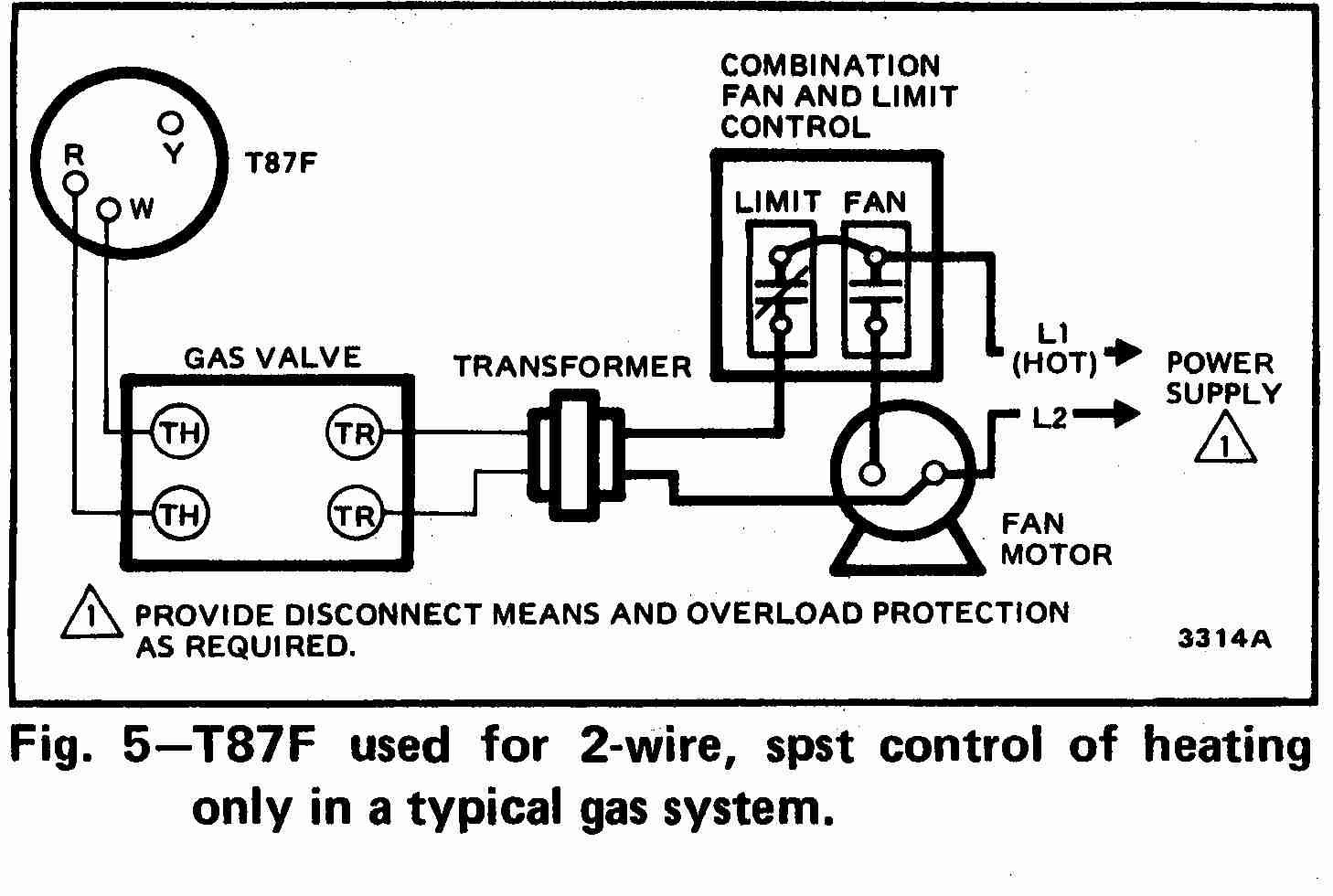
At left the thermostat wiring diagram illustrates use of a Honeywell T87F thermostat in a 2-wire application controlling a gas fired heating appliance.
In the Honeywell T87F thermostat series the single pole double throw switch makes (closes) one set of contacts when the temperature falls - to turn on the heating appliance.
A second set of contacts will make or close on temperature rise. This second set of contacts is typically used to operate a cooling or air conditioning system but may also be used to operate other controls or valves in some heating systems.
[Click any image or thermostat wiring schematic to see an enlarged, detailed version]
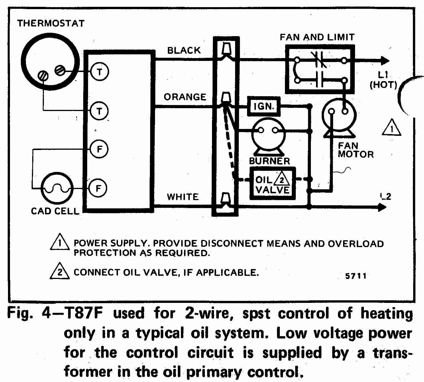
2-Wire Oil Heat Honeywell T87F Thermostat wiring diagram
Above the thermostat wiring diagram illustrates use of a Honeywell T87F thermostat in a 2-wire application controlling an oil fired heating appliance.
[Click to enlarge any image]
For a table of wiring connections for this thermostat also see
- TWO-WIRE HONEYWELL T87-F TYPE WALL THERMOSTAT WIRING - wiring details
- HONEYWELL CT87A,B,J ROUND® THERMOSTAT LOW VOLTAGE (15 TO 30 VAC) THERMOSTAT AND MOUNTING HARDWARE INSTALLATION INSTRUCTIONS (2002) [PDF]
- HONEYWELL T87F THERMOSTAT PRODUCT DATA SHEET & CIRCUIT DIAGRAMS [PDF] (2002)
3-Wire High Limit Honeywell T87F Thermostat wiring diagram
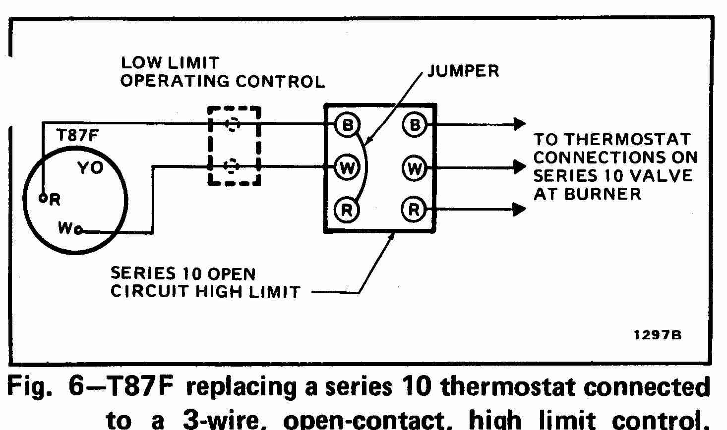
At left the thermostat wiring diagram illustrates use of a Honeywell T87F thermostat in a typical 3-wire, open contact, high limit control such as on an oil fired heating boiler.
3-Wire SPDT Honeywell T87F Thermostat wiring diagram
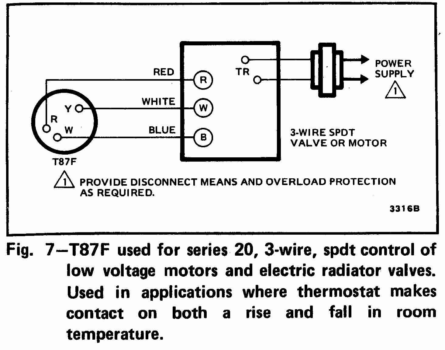
At left the thermostat wiring diagram illustrates use of a Honeywell T87F thermostat in a 3-wire application as a spdt (single pole double throw) switch such as used to control low voltage motors, electric radiator valves, zone valves.
The thermostat makes a contact on both a rise and on a fall of room temperature.
4-Wire Honeywell RTH2300 5+2 Programmable Thermostat wiring
At left the thermostat wiring diagram illustrates the typical wiring connections when installing a Honeywell RTH2300 (or similar) programmable room thermostat. Be sure to identify and label the existing thermostat wires before disconnecting them from the terminals on the old thermostat you are replacing.
Watch out: existing thermostat wires that will not be used in the new thermostat installation, such as wires attached to C or C1 terminals on the old thermostat should have their ends taped so as not to accidentally touch and short other thermostat wires or connectors.
Here is a copy of the HONEYWELL RTH2300/RTH221 SERIES PROGRAMMABLE THERMOSTAT OWNERS MANUAL [PDF]
Need More help? Call Honeywell at 1-800-468-1502 for assistance with your Honeywell thermostat.
Honeywell Series 10 Thermostats & Controls
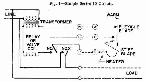
Honeywell Series 10 controllers such as the Honeywell R19A use a simple relay and built-in transformer and one or more line voltage contactors.
These are spst switch type controls (such as heat-only).
The No. 1 is a low voltage holding contact while the No. 2 is a line voltage contactor. The "coil" shown may be a magnetic coil that pulls in the armature of the No. 1 relay or it may be a relay type coil used in a gas control valve. The holding contact closes when the coil is energized.
In this sketch from a 1949 Honey Heating Control Handbook the thermostat has been satisfied (both contacts are open) and the system is not calling for heat. On a drop in temperature the flexible blade makes the white contact, and subsequently connects the stiff blade. On a rise in temperature the contacts break (or open) in the opposite order. [Line voltage circuits are not shown].
Symptoms of Broken or Shorted Thermostat Wires in a Series 10 SPST type circuit
Understanding the wiring details of series 10 controls and circuits can help us diagnose heating and cooling system operating snafus. Here are more examples from the Handbook.[12]
Symptoms of an open thermostat wiring circuit (broken wire, bad splice, loose screws)
- White wire broken: thermostat cannot pull in the relay and cannot hold it open - after a momentary shorting of the W-B terminals at the relay or valve
- Blue wire broken: thermostat cannot pull in the relay or valve, but once the relay is forced in (closed) the circuit can hold
- Red wire broken (or a loose heater plug screw) causes short cycling on the blue contact - single point operation
Symptoms of a short circuit in the thermostat wiring
- White wire shorted to the blue wire: relay or valve stays "on" unless all electrical power is shut off by the limit control switch, by disconnecting a wire at the low voltage transformer, or by turning off power to the system
- White wire shorted to the red wire: thermostat can start the heater's burner but can't stop it
- Red wire shorted to blue wire: short cycling (single pointing) on the white contacts alone
Mis-wiring of thermostat wires: wires connected to the wrong terminals
- White & blue wires swapped incorrectly: causes short cycling on the blue contact
- Blue and red wires swapped: short cycling on the white contact
- Red and white wires swapped: normal operation except that the heater is effective too quickly - resulting in short on-cycles and inefficient operation
More Honeywell Thermostat References & Guides
- [5] Honeywell Controls, the company wants you to use their contact form at this web page: http://www51.honeywell.com/honeywell/contact-support/contact-us.html
Honeywell Consumer Products, 39 Old Ridgebury Road Danbury, CT 06810-5110 - (203) 830-7800
World Headquarters, Honeywell International Inc., 101 Columbia Road, Morristown, NJ 07962, Phone: (973) 455-2000, Fax: (973) 455-4807 1-800-328-5111- Honeywell product model numbers & instruction Manuals: see http://yourhome.honeywell.com/home/Applications/FindYourModelNumber.aspx
- [12] "Heating Control Handbook for the Installer and Service Man,Oil Burner, Gas Burner and Stoker Controls", Honeywell Corporation, March 1949 [copy on file as HoneywellControlsHandbookSA1399-2-1949.pdf] . Some of the controls discussed in detail here include the
- Honeywell T1 and T11A = Series 10
- Honeywell T21A (T2) = Series 20
- Honeywell T847A = Series 80
- Honeywell RA117A (RA1) = Series 10
- Honeywell LA101A = Series 10,
- Honeywell LA419A (LA4) = Series 40
- V155A = Series 10, V435A = Series 40, V575A = Series 50, V835A = Series 80
Reader Comments, Questions & Answers About The Article Above
Below you will find questions and answers previously posted on this page at its page bottom reader comment box.
Reader Q&A - also see RECOMMENDED ARTICLES & FAQs
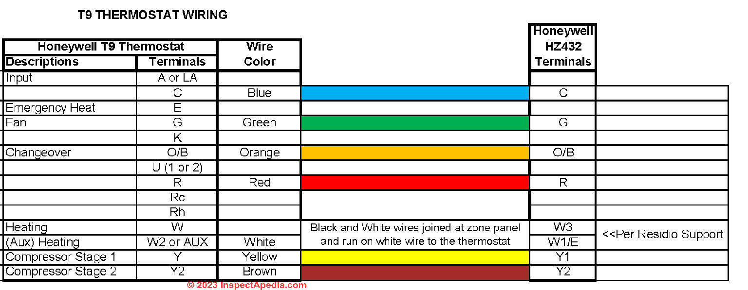
On 2023-07-20 by InspectApedia Publisher - wiring details for converting Honeywell HZ432 TrueZONE control panel utilizing Trane TCONT802AS32DAA Thermostats to Honeywell T9 thermostats
@Bob,
Excellent, Bob, we'll be sure to keep your notes and illustration with this article on Honeywell thermostats and to x-link it from our Trane page as these details will help other readers.
Thank you for taking the time to follow-up with the wiring details for converting Honeywell HZ432 TrueZONE control panel utilizing Trane TCONT802AS32DAA Thermostats to Honeywell T9 thermostats.
Working together makes us smarter.
[Note: this reader exchange is also posted at HOW WIRE A TRANE, GE, OR AMERICAN STANDARD THERMOSTAT]
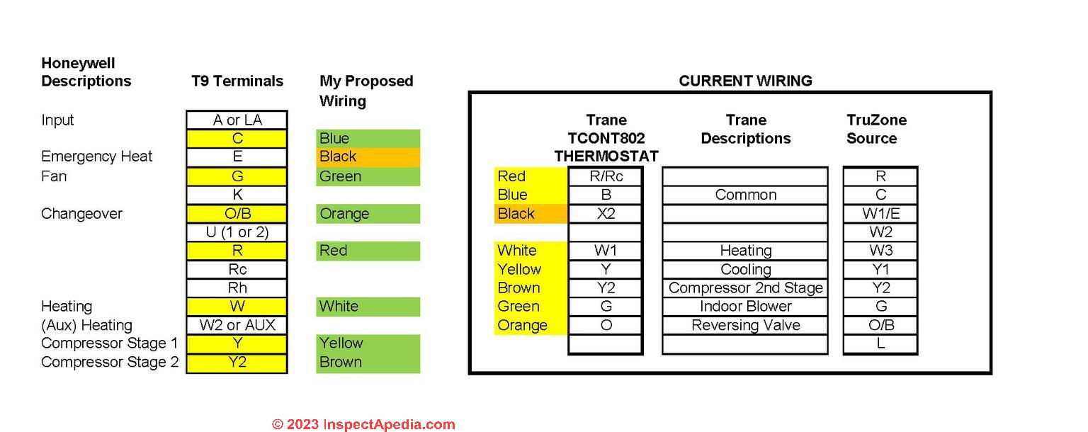
On 2023-07-19 by Bob - wiring dilemma solved
@Bob, SOLVED - The image below is my final / working wiring diagram.
On 2023-07-17 by Bob
@InspectApedia Publisher,
I called the Zone Board "Professional Help" line. when asked if I was a Pro I told him "I'm retired, so I guess I'm a homeowner". He offered help and said my wiring was correct except the black should be connected to AUX.
I asked if he meant W2/AUX and he said yes. I hooked it up and started the setup and was given an error message - "Invalid Wiring! You connected backup heat to the W1 terminal on the thermostat. Please use the W2/AUX terminal for the aux/backup heat instead."
Tried swapping the white and black but got the same message.
Frustration is building .
On 2023-07-17 by InspectApedia Publisher
@Bob,
I agree that it's very frustrating - a combination of several concerns can prevent a manufacturer from helping out a homeowner.
If you're up for reading wiring diagrams that can help, and if you don't have the IO manual for your Trane heat pump, we provide free PDF downloads for Trane as well as more contact information at
TRANE AIR CONDITIONERS & HEAT PUMPS
Give it a shot and keep me posted - your confirmation of wiring connections will sure help other readers.
On 2023-07-17 by Bob - frustrated with lack of customer support
@InspectApedia Publisher,
Yup. The 'Home' that handles the Thermostats say I need a Pro to tell me about the wiring conversion. The ZonePanel support is for Pros only. As a retiree on a fixed income (fixed before the Biden-flation) I need to try the DIY approach whenever possible. It's frustrating that the 'Home' support isn't allowed to talk about the Zone board output.
If I can't find any 'sure' affirmations on the wiring I may just risk installing one and hope for the best (no sparks or tripped circuts). Thanks for the input!
- Bob
On 2023-07-17 by InspectApedia Publisher
@BobT,
You're wiring guesses look reasonable to me but I want to emphasize that I'm at the limit of what I can say with confidence here.
Have you tried calling Trane customer support?
On 2023-07-15 by BobT - how do I convert wiring from Trane thermostat to Honeywell thermostat?
I have a Trane XL16i 4TWX6048 4- ton High Efficient two stage scroll heat pump with a Trane Variable Speed Air Handler: 4TEE3F49B1000AA with BAYHTR1419BRK resistance backup heat connected to a Honeywell HZ432 TrueZONE control panel utilizing Trane TCONT802AS32DAA Thermostats.
We want to replace these thermostats with Honeywell T9 (RCHT9510WFW) Thermostats. Honeywell support couldn't help with the wiring conversion.
Anyone have good advice? The image shows where I'm at so far. The Green indicates some confidence. Orange not so much.
On 2022-11-28 by InspectApedia (Editor) - How can I get heat with no white wire?
@Suliasi Tanaki,
Is this a new installation or an old one that has stopped working?
You may need to run a white C wire to the thermostat or install a local transformer.
On 2022-11-28 by Suliasi Tanaki
I have a old honeywell HW SV9500 with only 4 wire Red, Black, Green and Yellow when open furnace only Red, Green and Yellow is connected but I need heat but with no white wire. How can I get heat with no white wire?
On 2022-10-03 by InspectApedia-911 (mod) - White Rogers thermostat guide
@Russell,
https://inspectapedia.com/heat/White_Rodgers_Thermostat_Wiring_Guide.php
WHITE ROGERS THERMOSTAT GUIDE
Hope I help you out but of course you want to be sure you're reading the instructions for the specific model White Rogers thermostat that you have purchased.
On 2022-10-03 y Russell
I had new Honeywell Zone valves installed on a gas furnace. The White Rogers Thermostat has White, Red and Blue wires. When the valves were installed, they disconnected the Blue wire. Is this Blue wire a Common that can be used for a WIFI thermostat?
On 2022-04-19 by Inspectapedia Com Moderator - White Rodgers wiring guides and manuals
@Joe Z.,
It's informative to see how a White Rodgers thermostat would have been wired -
THERMOSTAT WIRING WHITE RODGERS
Then over at ZONE VALVE MANUALS & WIRING you'll find White Rodgers zone valve wiring manuals including the WR 1311
On 2022-04-17 by Joe Z.
I am planning to install a Honeywell RTH9585WF Programable Thermostat to control a 24 volt hydronic zone valve that draws .4 amps. The contacts in the thermostat are rated at 1 amp so that should be OK. I am willing to supply an additional wire to supply continuous power to the thermostat.
I could not obtain an answer on wire termination points to control a White Rodgers Type 1311 zone valve from Honeywell. The white wire opens the valve when the system makes a heat call. The Yellow wire causes the valve to close when the system is satisfied. (24 volt power is required to close the valve.) Red is 24 volts from one side of the transformer that supplies the power to the valve.
The thermostat simply needs to act as a SPDT switch to supply power to the motor to open and close the valve. I have not been able to determine the termination points on the thermostat to allow it to act as a SPDT switch in the heat mode.
On 2021-11-26 by Inspectapedia Com Moderator
@Karl H.,
I'm not sure if I understand your situation exactly correctly, but it sounds as if your zone valves are models that are normally open and that requires signal to close them. It's probably a simple wiring change.
I think the best way we can sort this out is to look at the wiring diagram for the correct model zone valve. So give us the specifics of your zone valves and together we can go to our page where we have the wiring instructions for that model.
On 2021-11-25 by Karl H.
I have 30 year old White Rogers 3 wire mercury switch thermostats running power on and power off White Rogers zone valves in a radiant heating system in Alaska, no air conditioning. All working excellent, but I would like to install a modern thermostat.
My thermostats have closed circuit between R (red wire) and Y (green wire) when no heat is called for. When heat is called for, the R&Y open and the R & W (white wire) closes.
I bought a Honeywell T6 Pro Z-Wave, thinking I had a three wire "Series 20" system.
Wrong. It will power open the zone valve, closing R&W, but when upper temp limit is reached, no apparent way to close R&Y.
So how can I power close my zone valves? Thanks
On 2021-09-18 by inspectapedia.com.moderator - it's okay to have an unused wire capped off if no longer needed
@Bob L,
From your description it sounds as if perhaps an earlier installation ran both heat and AC from a common thermostat that was later switched to "heat only", leaving the Cool wire unused at the old thermostat.
At any thermostat it's common to see some of the wires capped off or just wound back around the incoming bundle if they're not used. Especially that's true at a heat-only TT.
On 2021-09-17 by Bob L
We purchased a 30 yr old home that has central AC (outside and attic), and a combo furnace/hot water on demand (garage), each with it's own thermostat. So as everything sits, you have the possibility of mistakingly having both heat and AC on at the same time. I'd like to replace the two thermostats with one that will operate both.
The heat set up is what is confusing me. there is a four strand wire ( R W Y B ) that runs from thermostat to garage. In the garage end, the R & W are connected to the furnace. The Y & B are connected to a transformer that sits along side the furnace. At the thermostat end, it is a Honeywell "Heat Only" CT87K, it has the R W Y connected to it. The B hangs loose, connected to nothing.
I don't understand the B connected to the transformer on the one end, but loose on the other.It would seem wrong, but the system works. The Y also confuses me in that most any other system, Y would be AC, but this thermostat is advertised as "Heat Only".
On 2021-04-10 by danjoefriedman (mod) - Honeywell Duo Therm motorhome thermostat wiring
@Vicki,
Red is common voltage and white is heater or furnace
All of the wires are nicely labeled
On 2021-04-10 by Vicki
We are trying to replace a Dometic Duo Therm Thermostat with a Honeywell RTH6360 in our Motorhome. We just want to wire up for the Gas Furnace heating. We are having trouble matching the wires on the Duo Therm to the Honeywell. I have added a photo of the Duo Therm Wiring. Can you please help?

On 2021-03-25 by danjoefriedman (mod)
@wayne, the 8-wire link I gave describes the usual brown wire connection & purpose.
On 2021-03-25 by wayne
@danjoefriedman,
the honeywell hookups show (on the left side) c, k, rc, and r. the right side is w-o/b, y, g, w2-aux/e, y2, and L. if i hook the Orange to the w-o/b, and the white to the w2-aux/e, where would the brown wire go which was to w/e on previous tsat?
On 2021-03-24 by danjoefriedman (mod)
@wayne, does this help
THERMOSTAT WIRE CONNECTIONS - 8-WIRE Black, Red, White, Yellow, Green, Orange, Brown, Blue
On 2021-03-24 by wayne
I currently have American Standard heat pumps with propane furnaces' as back up. current wire configurations are Blue to C, Orange to O, Brown to W/E, White to W2,(with a jumper connecting the W/E and W2) Red to R, Green to G, and Yellow to Y. on my new Honeywell RTH9585, I need help with where the White and Brown go, and do I leave the jumper in the new Honeywell tstat?
On 2021-03-17 by danjoefriedman (mod)
@Mark, really glad this worked for you
On 2021-03-17 by Mark
inspectapedia.com.moderator,
Tried for hours looking up diagrams, from old units to new thermostats.
I almost cried after reading your article. R is for red and also Rc but they seem to be bridged now. Y is for yellow, w is for white, don't bothered with common. Thanks so much man. It worked! Ill give a tramp $20 on your behalf tonight.
On 2020-11-19 by danjoefriedman (mod) - oil heat furnace not coming on
Jerry
Let's start by eliminating the thermostat from the equation.
Ask your heating service tech to do the following:
At the boiler disconnect the thermostat wires from the primary control - you'll see the two T T terminals, usually in the aquastat or primary control.
Then jumper the two TT terminals - at that same control. That's the same, functionally, as a thermostat calling for heat.
If the boiler runs there's a problem with thermostat wiring or possibly the thermostat itself.
A thorough list of diagnostic steps is at NO HEAT - BOILER
On 2020-11-19 by jerry and Brenda Slayton
we have a rth2300/rth221 thermostat.only for oil heat furnace.have 3 wires from wall,black,white,red.hot water baseboard heat.problem:i turn to 62 at night.outside temp. last night was 18 degrees but in house was 52 when we awoke.how come it doesnt come on when temp. goes below 62 degrees?
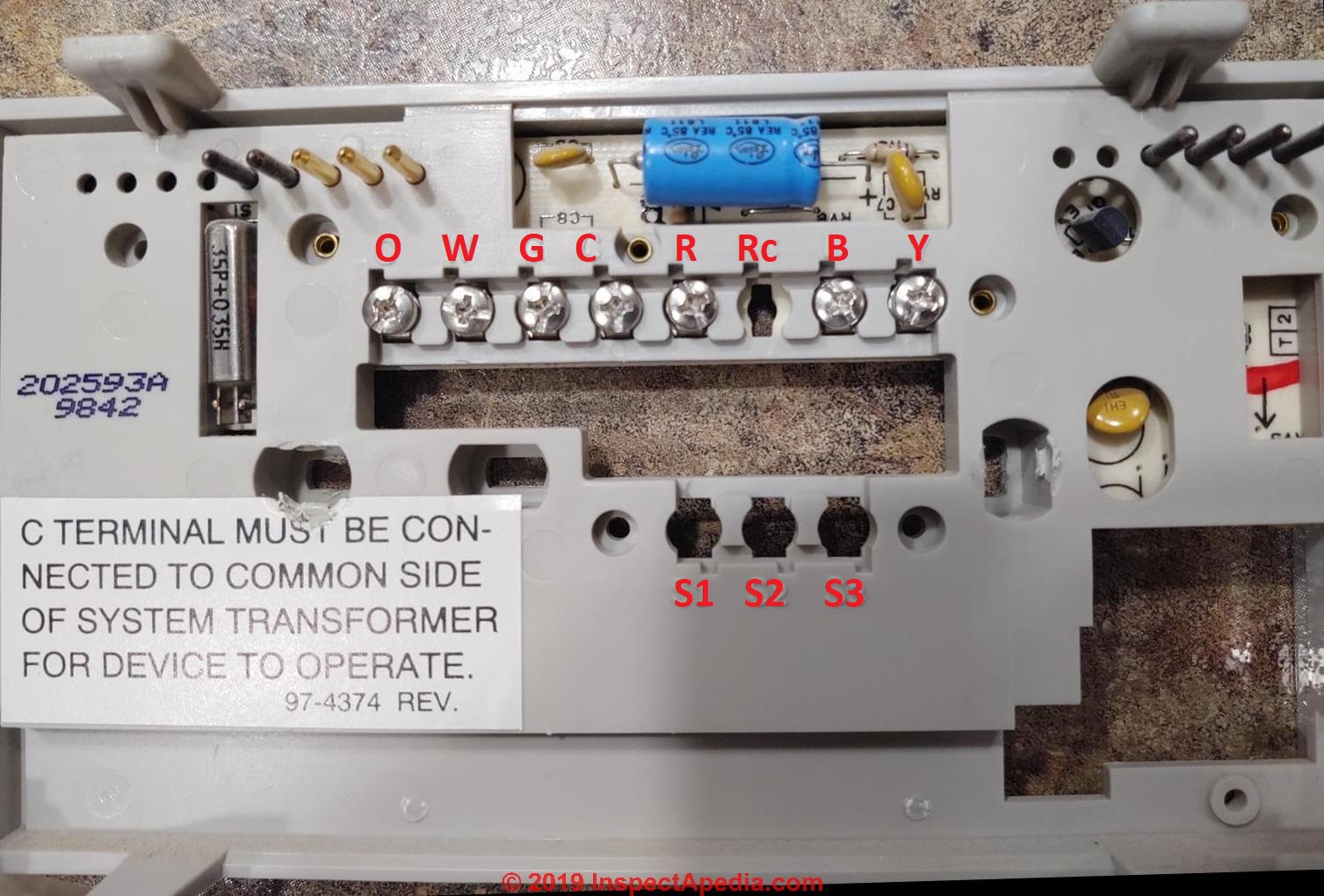
On 2020-01-01 by (mod) -
Even when the wire itself is not easy to decode or see color, you should see an r and a w on the wiring base. Since it's alternating current or AC it shouldn't be critical
On 2020-01-01 by Ken
I have an old 2 wire that has no markings. Is the red or white on the left on the base?
On 2019-12-28 by (mod) -
Free - Honeywell is saying that in the Chronometer III thermostat the C or "common" wire at the thermostat should come from the C or "common" terminal at the low voltage transformer.
That's wiring coming through the wall from your heating system or its transformer. not a jumper in the thermostat.
On 2019-12-28 by freedompools.bayareatx
I'm replacing an old 4-wire(R,Y,G,W) Honeywell mercury thermostat with a digital Honeywell Chronometer III that says
'C terminal must be connected to common side of system transformer for device to operate'.
Is there a way to jumper that with one of the 4 wires I have?
On 2019-01-22 by (mod) - Old thermostat has an O wire, new thermostat does have O port.
Rob,
at THERMOSTAT WIRE CONNECTIONS - 6-WIRE Red, White, Blue, Yellow, Green, Orange Wires
we give the use of the O or "orange" wire.
The new thermostat ought to include a wiring instruction that tells you where that wire goes on their model.
On 2019-01-21 by Rob
Converting a heat pump thermostat to a HONEYWELL. Old thermostat has an O wire, new thermostat does have O port. What should I do?
On 2018-12-26 by (mod) -
Bruce
If your dad's wall thermostat is controlling both heat and air conditioning still most digital Honeywell thermostats will work just fine and any model will include specific wiring connection instructions for the R W Y O G and Black wires in your existing setup.
To understand the usual or "standard" connections, and because you say there are six wires in use in the current thermostat, in the suggested reading links above titled
Thermostat Wiring & Installation Articles
take a look
at THERMOSTAT WIRE CONNECTIONS - 6-WIRE Red, White, Blue, Yellow, Green, Orange Wires
which has a live link there to jump right to that article
On 2018-12-26 by Bruce McPherson
Was going to replace my fathers wall thermostat with a digital honeywell ,it is old,the thermostat is a carrier type,there r 2 #"S on it,hho1ad040c +t87f 2907.
My father has a gas furnace a outside air conditioner + a 2 stage blower fan,the terminals on the old thermostat are r-red wire,w-white,y-orange, g-green + a -black(confused over this wire).
What honeywell digital wall thermostat should I get + where would the wires go on the new thermostat,thanku,bruce,my email is buffalomagoo@hotmail.Com
On 2018-12-09 by (mod) - Honeywell thermostat for home, model: RTH8500
I need to be clear that I don't understand your exact situation, in part because I don't know what thermostat wiring is present in your home. Some thermostat systems, in fact most but not all of them, rely on the 24 volt power provided by the thermostat circuit.
I have encountered thermostats the only operated off of battery power because voltage wasn't being delivered by the thermostat circuit.
On 2018-12-05 by rogerlange206@gmail.com
I purchased a Honeywell thermostat for home, model: RTH8500. With normal installation procedure, when I remove the batteries, the system appears to stop working. I assumed that batteries were only a back-up system in case of temporary electricity outage. Am I wrong?
Roger
On 2018-11-18 by (mod) -
No, Ian.
Just cap off the unused wire.
On 2018-11-16 by Ian
I have a 3 wire boiler heat system Red,White, Green but was only using red,and White I bought the honeywell RTH5160 Series do I need connect the Green wire
Forgot to mention it's a non programmable thermostat RTH5160
...
Continue reading at THERMOSTAT INSTALLATION STEPS or select a topic from the closely-related articles below, or see the complete ARTICLE INDEX.
Or see THERMOSTAT WIRING HONEYWELL FAQs - questions and answers posted originally on this page
Or see these
Recommended Articles
- CONVERT LINE to LOW VOLTAGE THERMOSTAT - Aube Technologies line voltage thermostats e.g. for electric heat baseboards (Honeywell)
- MERCURY HAZARDS in APPLIANCES & GAS REGULATORS - including HVAC thermostats
- THERMOSTAT INSTALLATION STEPS - how to replace or install a new thermostat
- THERMOSTAT WIRING COLOR CODES & methods for identifying which thermostat wire is which if yours have lost their labels or have unclear color codes.
- THERMOSTAT WIRE CONNECTIONS detailed room thermostat installation & wiring guide for each heating or cooling system type and each thermostat brand / model
- COMMON WIRE at THERMOSTATS
- CONVERT LINE to LOW VOLTAGE THERMOSTAT
- THERMOSTAT WIRE CONNECTIONS - 2-WIRE like the T87F
- THERMOSTAT WIRE CONNECTIONS - 3-WIRE Red, White, Blue Wires
- THERMOSTAT WIRE CONNECTIONS - 4-WIRE Red, Yellow, Green, White
- THERMOSTAT WIRE CONNECTIONS - 5-WIRE Blue/Black, Red, White, Yellow, Green
- THERMOSTAT WIRE CONNECTIONS - 6-WIRE Red, White, Blue, Yellow, Green, Orange Wires
- THERMOSTAT WIRE CONNECTIONS - 8-WIRE Black, Red, White, Yellow, Green, Orange, Brown, Blue
- THERMOSTAT WIRE SORTING to ID R W B
- THERMOSTAT WIRING OPENING SEAL
- THERMOSTAT WIRING in PARALLEL / MULTIPLES
- THERMOSTAT WIRE TERMINAL ID CODES / FUNCTIONS - what are the R, W, and other thermostat wire terminals used for?
Suggested citation for this web page
THERMOSTAT WIRING HONEYWELL at InspectApedia.com - online encyclopedia of building & environmental inspection, testing, diagnosis, repair, & problem prevention advice.
Or see this
INDEX to RELATED ARTICLES: ARTICLE INDEX to HVAC THERMOSTATS
Or use the SEARCH BOX found below to Ask a Question or Search InspectApedia
Ask a Question or Search InspectApedia
Questions & answers or comments about heating, air conditioning, and heat pump thermostat installation and wiring
Try the search box just below, or if you prefer, post a question or comment in the Comments box below and we will respond promptly.
Search the InspectApedia website
Note: appearance of your Comment below may be delayed: if your comment contains an image, photograph, web link, or text that looks to the software as if it might be a web link, your posting will appear after it has been approved by a moderator. Apologies for the delay.
Only one image can be added per comment but you can post as many comments, and therefore images, as you like.
You will not receive a notification when a response to your question has been posted.
Please bookmark this page to make it easy for you to check back for our response.
Our Comment Box is provided by Countable Web Productions countable.ca
Citations & References
In addition to any citations in the article above, a full list is available on request.
- [10] Domestic Central Heating Wiring Systems and Controls, 2d Ed., Raymond Ward, Newnes, ISBN-10: 0750664363, ISBN-13: 978-0750664363, Quoting from Amazon.com:
This unique A-Z guide to central heating wiring systems provides a comprehensive reference manual for hundreds of items of heating and control equipment, making it an indispensable handbook for electricians and installers across the country. The book provides comprehensive coverage of wiring and technical specifications, and now includes increased coverage of combination boilers, recently developed control features and SEDBUK (Seasonal Efficiency of Domestic Boilers in the UK) boilers ratings, where known.
In addition to providing concise details of nearly 500 different boilers fuelled by electric, gas, oil and solid fuel, and over 400 programmers and time switches, this invaluable resource also features numerous easy-to-understand wiring diagrams with notes on all definitive systems. Brief component descriptions are provided, along with updated contact and website details for most major manufacturers. - In addition to citations & references found in this article, see the research citations given at the end of the related articles found at our suggested
CONTINUE READING or RECOMMENDED ARTICLES.
- Carson, Dunlop & Associates Ltd., 120 Carlton Street Suite 407, Toronto ON M5A 4K2. Tel: (416) 964-9415 1-800-268-7070 Email: info@carsondunlop.com. Alan Carson is a past president of ASHI, the American Society of Home Inspectors.
Thanks to Alan Carson and Bob Dunlop, for permission for InspectAPedia to use text excerpts from The HOME REFERENCE BOOK - the Encyclopedia of Homes and to use illustrations from The ILLUSTRATED HOME .
Carson Dunlop Associates provides extensive home inspection education and report writing material. In gratitude we provide links to tsome Carson Dunlop Associates products and services.
 | HOME | ABOUT | ASK a QUESTION | CONTACT | CONTENT USE POLICY | DESCRIPTION | POLICIES | PRIVACY | |
| © 2024 - 1985 Publisher InspectApedia.com - Daniel Friedman | |||||||||