
InspectAPedia® FREE Encyclopedia of Building & Environmental Construction, Diagnosis, Maintenance & Repair |
Question? Just ask us! InspectAPedia
|
 Electric Motor Starting Capacitor Wiring & Installation
Installation Wiring Guide to Air Conditioning Compressor Motor & Other Electric Motor Start-Boost or Run Capacitors
- POST a QUESTION or COMMENT about installing a hard-start capacitor to get an air conditioner motor, fan motor, or other electric motor running.
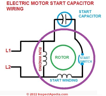
How to hook up an electric motor start or run capacitor:
This article gives electric motor start-run capacitor installation & wiring instructions for electric motor capacitors designed to start & run an electric motor such as an AC compressor, heat pump compressor or a fan motor, and how to wire up a hard-starting air conditioner compressor motor, fan motor, to get an air conditioner, heat pump, refrigerator, or freezer compressor or other electric motor (such as a well pump) going.
This electric motor capacitor article series explains the selection, installation, testing, & use of electric motor starter start and run capacitors used on various electric motors found in or at buildings such as air conditioner compressors, fan motors, some well pumps and some heating equipment.
InspectAPedia tolerates no conflicts of interest. We have no relationship with advertisers, products, or services discussed at this website.
How to Install and Wire Up an Air Conditioner Compressor, Blower Motor, or Fan Motor Starting Capacitor
 Whether you are simply installing a replacement start or run capacitor, or you are installing a "hard-start" capacitor to try to keep a troublesome electric motor going, the procedures for choosing and installing the capacitor are the same.
A "hard-start" motor capacitor is simply a capacitor that gives a bit of extra boost or torque to try to get a motor spinning.
[Click to enlarge any image]
When an electric motor, such as an A/C motor, is having trouble starting, it's common for the service technician to simply try swapping-in a new starting capacitor. That's because that step is quick, easy, and inexpensive.
It also makes sense because most electrical problems in air conditioning systems are in the compressors and their relays or motor overload switches.
But keep in mind that the underlying problem might be a more serious failure inside the motor itself, such as a broken start or run motor winding or a failed motor bearing. In a single phase (common residential A/C) compressor you can verify with an ohmmeter whether or not the A/C compressor is bad. We describe that procedure separately
at ELECTRIC MOTOR DIAGNOSTIC GUIDE.
Before swapping in a new start or run capacitor we have to know which terminals on the motor will be used.
In our capacitor testing and wiring sketch above and in our explanatory table below, you note we use the letters S, C, and R to identify the usual terminals to which a start/run capacitor is wired. On many systems these terminals may already be labeled so that the three leads on a start/run capacitor can be wired correctly:
- S = start wire connector
- R = Run wire connector
- C = common connector
But what if there are no markings.
Watch out: do not proceed to hook up a start or run capacitor to a motor before you have the correctly identified the motor capacitor terminals. Otherwise you may damage the motor.
How to Identify the Start, Run, and Common Capacitor Terminals on an Electric Motor
 The terminals on an electric motor should be marked as S - R - and C for Start, Run, and Common.
But what if those markings have been lost. Before you can know how to connect a replacement start or run capacitor to a motor you must know which motor terminals are which.
We can figure out which terminals are which easily and quickly by a simple procedure we give here. A fractional horsepower electrical motor should show different electrical resistance between the three terminals (Start, Run, and Common) as we explain in step-by-step detail just below.
Watch out: Turn off electric power before checking or touching electric motor terminals or performing tests. You may also need to discharge any capacitor terminals to ground to avoid getting a shock.
Watch out: live high voltage may also be present at a capacitor, capable of giving a tremendous electrical shock even after electrical power has been disconnected at the equipment. Never work on live electrical equipment.
Also see STARTING CAPACITOR SAFETY
To start, we simply label the three terminals arbitrarily as A-B-C and then measure the resistance between each possible pair and write down the result.
Use your VOM in the OHMS setting to test the resistance between each pair of two of the three motor electrical connection terminals by testing each pair of terminals in succession.
You will see that the resistance will be different among the each of the three possible pairs of terminal connections: A-B, A-C, and B-C.
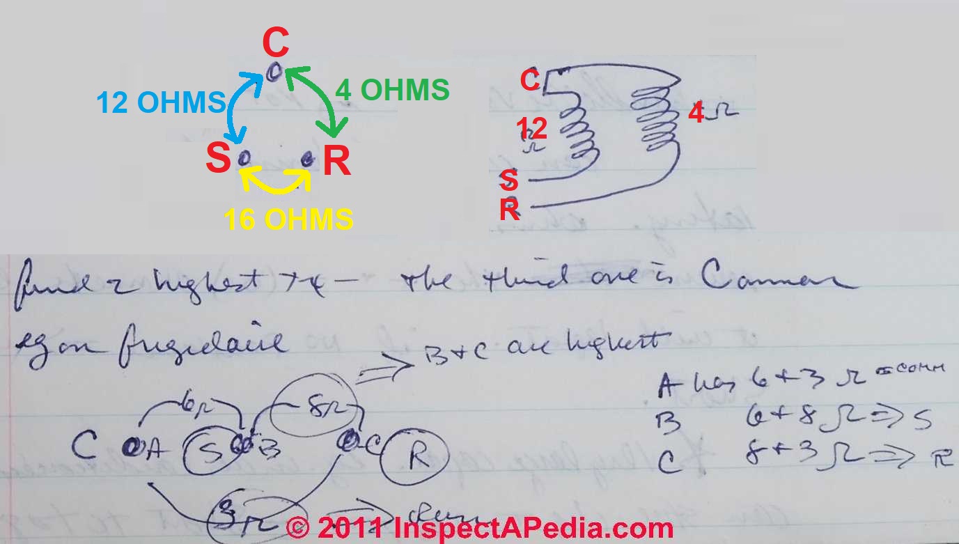
Our example table below shows the typical resistance differences among Common, Start, and Run terminals for a Frigidaire A/C compressor motor.
A/C or Heat Pump Motor |
Resistance Ohms Between Unidentified Terminal Pairs |
||
| Terminal | A <-> B | A <-> C | B <-> C |
A: = Common C because its |
6-Ohms |
3-Ohms |
8-Ohms |
| B: - Start S because its 2 readings are 6 & 8 Ohms 6+8 = 14 = Highest |
|||
| C:- Run R because its 2 readings are 8 & 3 Ohms 8+3 = 11 = In-Between |
|||
- Before we know which of the three terminals are actually Common, Start, and Run, we label them arbitrarily as A, B, and C.
|
By comparing the resistance between each pair of these three we can figure out which is the C or Common, and which is S - Start and R - Run as follows: - Find the two highest resistance terminals by adding resistance measurements as shown in the table above. For example the
The A-terminal has two resistance measurements: A<->B and A<->C of 6 and 3 Ohms. Add those together to get a total of 9.
The B-Terminal has two resistance measurements: A<->B and B<->C of 6 and 8 Ohms. Add those together to get a total of 14.
The C-Terminal has two resistance measurements: A<-C> and B<->C of 4 and 8 Ohms. Add those together to get a total of 11. - We see that the terminal with the lowest total resistance (9) is A so we label that as C the common terminal.
- We see that the terminal with the highest total resistance (14) is B so we label that as S the start terminal to which the starting capacitor is wired.
- We see that the terminal with total resistance in-between (11) the other two is C so we label that as R the run terminal to which the run capacitor will be wired.
How to Identify the Motor Run Speed
Incidentally, as a side note, while most electric motors are marked with a data tag indicating the motor run speed (in RPMs), it's worth noting that the number of run coils is what determines the run speed of the motor.
By visual inspection of the motor or its interior, two coils marks a motor that runs at 3450 rpm (3600 rpm "nominal"), while
4 coils marks a 1725 rpm motor.
Simple Relay and Hard Start Capacitor Wiring Instructions - Example 1
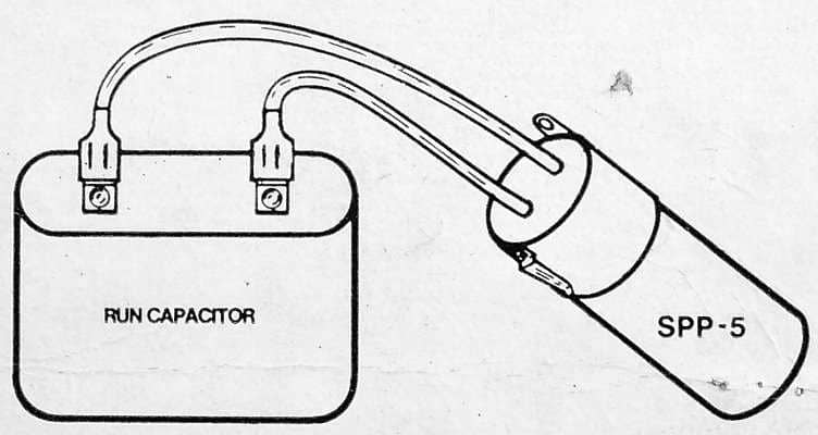
Relay and hard start capacitors such as the Starter Pow-R-Pak sold by Sealed Unit Parts Co., can be installed with no wiring changes to the original system whatsoever. Quoting from Part No. SPP-5, a relay and hard start capacitor sold by that company:
Connect the two wires from the SPP-5 in parallel with the [existing, already installed] run capacitor (one wire each side) without removing any original wires.
Use special "piggy back" terminal of the SPP-5 if all the run capacitor terminals are being used. [Install only on PSC units equipped with run capacitor.]
Simple Relay and Hard Start Capacitor Wiring Instructions - Example 2
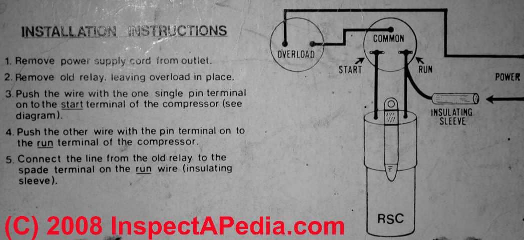
Here are some sample capacitor installation instructions for adding a motor starter capacitor to an air conditioning compressor motor - taken from the product package for a relay and start capacitor intended for use on a refrigerator or freezer. Similar starter capacitors are available for air conditioning compressors.
[Click to enlarge any image]
- Remove the power supply cord from the electrical outlet -
in other words, be absolutely certain that electrical power has been turned off to the equipment being serviced. - Remove the old starting relay,
leaving the old overload protection in place. - Push the wire with the one single pin terminal onto the "start" terminal
of the air conditioning compressor. (See the wiring diagram above). - Push the other wire with the pin terminal onto the "run" terminal
of the air conditioning compressor. - Connect the line from the old starting relay to the spade terminal on the "run" wire (insulating sleeve).
- Restore electrical power
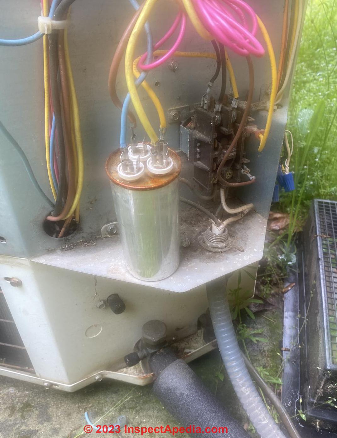
Start / Run Capacitor Mounting Positions
 Start/run electric motor capacitors can be mounted in any direction or position. However there are some other capacitor mounting considerations that can affect capacitor life: basically you want to minimize the capacitor's exposure to vibration and heat.
As AFCAP points out, ..."the temperature on the surface of the capacitor cannot exceed, even under the worst conditions, the maximum permitted temperature.
It is advisable to make an experimental measurement of the temperature reached by the capacitor under the working conditions in the final application and after the thermal equilibrium has been achieved." - Supco [2]
Watch out: Air Conditioner Motor Starting Capacitor Safety warnings:
When testing a compressor, one must discharge the capacitor first!
It'll otherwise have enough power stored on it to be at least very painful. (Author and others have been zapped!)
Some systems will automatically discharge the capacitor, but shorting its leads [to ground] with a screwdriver (after verifying that the power's off) is a safe way to ensure that you won't get shocked. Motor starting capacitors can hold a charge for days!
If oil has leaked out of a capacitor:
Don't touch any oil that leaked out: old capacitors may contain PCB oils, an extremely carcinogenic (cancer causing) material which require special disposal.
Once the capacitor has been discharged (as described just above),
then it can be tested with a multi meter. Either use the meter's built in capacitor test function, or use this trick: Charge the capacitor by using the sense current the meter puts out when set to ohms.
You should observe a rapidly rising resistance before the meter indicates over range/infinity.

Disconnect the test leads, and switch over to volts. Then, reconnect the test leads. A voltage reading should be observed, approaching zero.
If the capacitor doesn't hold a charge, or the resistance reading never approaches infinity, it probably needs replacement.
Also, the capacitor may be defective if the compressor hums but does not start. Visual inspection may reveal it to be bulged, or have a blown out safety plug.
Start / Run Capacitor & Fan or Compressor Motor Wiring Color Codes & Connections
On 2017-07-09 by Brian Render
I'm replacing my run capacitor in my air handler. I forgot to mark the wires I took off. I have 4 wires. A blue, a black, a yellow, and a brown. Brown , and yellow come from the motor. Red, and black go to a control box. What goes where?
On 2017-07-09 by (mod) Typical color codes & wiring connections for an air handler blower fan or a compressor/condenser fan & compressor wires
Brian:
RE: wiring up an HVAC air handler fan motor capacitor:
You reported four but listed five wires in your air handler and that were connected to the run capacitor:
- BLUE
- BLACK - to a control box
- YELLOW - from motor
- BROWN - from motor
- RED - to a control box
- typically wires to C
The reason you can spend hours looking at online chats about HVAC start-run capacitor wiring without finding a single absolutely right guide to capacitor wiring color codes is that the service techs who make these repairs don’t want to give an answer that kills someone or burns up their equipment.
Watch out: touching live voltage can kill you. Turn power off and discharge any capacitors before touching anything. A capacitor can store a charge that can hurt you or worse even after power has been turned off. If you’re not sufficiently trained and informed about electrical repairs, hire someone who can do the work properly and safely.
The tech will typically use an insulated screwdriver to short the F or H terminals to the COM terminal to discharge the cap.
While there are common capacitor wiring color conventions that I will cite below, the actually correct wire colour match to fan motor terminals, wires, and capacitor terminals may vary by motor brand, age, model and application. But there are steps that can help sort out which wires go where.
Next time, remember to tag each wire with an ID and write down its connections before removing wires from their connections on electrical equipment.
Watch out: It's safest to take a look at the wiring diagram on the equipment itself - you can follow them to the marked terminals on your start or run capacitor. There are also some simple VOM tests that can help identify motor terminals.
Look at the wiring diagram for your specific HVAC equipment and find the capacitor where you’ll see its wires and their identities. You should see a wiring diagram glued to the inside of the air handler cabinet or to the inside of the blower compartment door.
You can also obtain a wiring diagram for your air handler brand, model, serial number from the manufacturer, or give us that information and we’ll help dig it out.
Now with all that scary arm waving done:
- Look at the blower fan motor’s data tag where it should give wiring terminal identifications.
- A tech will also follow the wires from their loose end back to their source that then can be matched to the normal connections given below.
- A tech will also test the motor to identify its different terminals if the markings are obscured.
- On a multi-speed motor you can use a VOM to measure resistance between common and speed wire from the motor: higher resistance means a lower speed rotation
See TEST the MOTOR to ID TERMINALS
Blower fan motors and other fan motors may have what look like extra wires, not all of which may be in use, depending on the fan speeds required.
- Simplest case: a single speed motor (fewest wires): typically 3 wires: start, run, common
- More complex case: a motor that supports 2 or 3 speeds.(High, Medium, Low) - adding 2 or 3 wires
- More complex case: a motor that also can have its run direction swapped between clockwise and counterclockwise - adding 2 to 4 wires.
HVAC Capacitor Wiring Number of Terminals & Wiring Color Codes & Terminal Identification Codes
- If an HVAC fan motor capacitor just has 2 terminals on its top, they will be F-fan and C-common
- If an HVAC motor capacitor has 3 terminals they will be marked
F = FAN
H = Herm/Compressor
C = COM (connects to the contactor to provide power to the capacitor) - HVAC Motor Standard Terminal Codes:
R = RUN
S = START
C = COMMON
Usually the following wire colors will connect to the terminals or sources or controls we list below - you’ll see data like this (though the colors may be different) on the wiring diagram for your own equipment.
Watch out: Your equipment’s wiring diagram and what its manufacturer tells you will be the final authority on which connections are correct.
Note: HVAC service technicians are invited to CONTACT us to improve these general color codes & wiring tips for start/run capacitors, dual capacitors, and fan or compressor motors. We are happy to cite, credit, and refer readers to expert sources & technical content contributors.
HVAC Capacitor Wiring Color Codes & Connections - Basics |
||
| Wire Color | Typical Connections Compressor/Condenser Unit |
Typical Connections Blower Assembly / Fan |
| Black | Power source. Usually connects to C or Common terminal on the Capacitor Compressor contactor relay T1 to C on the Compressor motor terminal Black also wires from Compressor Contactor T1 to T5 on Start Relay |
Air handler unit blower fan motor to T1 terminal on contactor relay Power from a fan relay to the fan motor |
| Red - power source | Power source. Usually connects to R or Run terminal on the Capacitor. Compressor contactor relay T2 to R on the Compressor motor terminal |
Power from fan relay to fan motor will typically connect to the T2 terminal on the Contactor relay. For multi-speed fans red = low speed motor terminal |
| Blue | Two blue low voltage wires to operate the contactor relay magnet Often: Compressor R or Run terminal to S on the Compressor Start capacitor |
Power for medium speed motor terminal |
| Brown | Fan motor to capacitor (motor start terminal) Connects fan to the F or FAN terminal on the capacitor to fan motor |
Fan motor to the capacitor (from the motor start terminal) Connects the Fan motor to the F or FAN terminal on the capacitor for the fan motor |
| Brown + White | Same use as white wire, C on capacitor to T2 on contactor Not used when using a dual start/run cap |
Same use as white wire, C (common) on capacitor to T2 on contactor Not used when using a dual start/run cap |
| Green | Ground wire in nearly all systems | |
| Orange | From power terminal on fan motor to C or COM on the capacitor Outdoor Fan Motor to C or COM or RC connector on the Run or Start/Run Capacitor |
For multi-speed fans, orange is medium-low speed |
| Purple | S terminal on Compressor to HERM or H on the Run or Start/Run Capacitor May be ground or neutral. |
Fan motor direction reverse to counterclockwise if grounded - connect purple to yellow to reverse. Connect from fan to the COM terminal on the capacitor |
| Red | Compressor contactor relay T2 to R on the Compressor Start Relay T1 to C on a separate Start Capacitor |
|
| Yellow | Compressor to the H or HERM terminal on the capacitor Often: Compressor Start Relay to C on the Compressor Start Capacitor |
From a fan motor controls the medium speed motor |
| White | Common wires connect to the grounded (neutral ) side of power source | Common wires connect to the grounded (neutral) side of power source |
Notes to the table above:
Watch out: The wire color codes used in the motor capacitor wiring table above show the most common or "standard" conventions that might help you identify which wire in the electric motor wiring harness goes where and what it does.
But keep in mind that your motor and its wire colors and uses may indeed be different. It's always best to identify the brand and model of your electric motor and to find its wiring diagram.
Look right on the motor itself: often its wiring will be given in a sticker or data plate.
Wire Connector Swaps to Change Motor Speed
Electric motor speed taps: typically L2 connects to
- L-2 to Black = high speed
- L-2 to Blue = medium speed
- L-2 to Red = low speed
Wire Connector Swaps to Change Motor Rotation Direction
- Purple to purple = rotate clockwise
- Purple to yellow = rotate counter-clockwise
Example Source: DAYTON ELECTRIC MOTOR WIRING DIAGRAM [PDF], Dayton Electric Mfg. Co., 5959 W. Howard St., Niles IL 60714 USA, retrieved 2017/07/09, original source: Grainger.com
Start & Run & Dual Capacitor Specification References
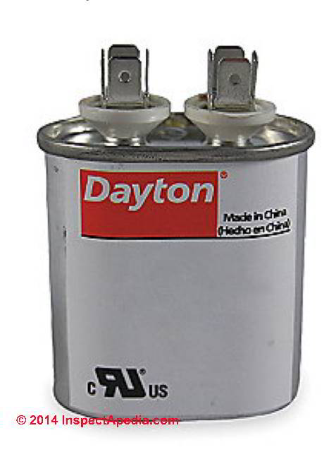 At left is a simple two-terminal run capacitor.
- COPELAND ELECTRICAL HANDBOOK [PDF] free download from Emerson Climate Controls, at InspectApedia.com
- Essex, Brown: "Motor Repair Supplies" (Catalog), Essex Group, Inc., 1601 Wall St., Fort Wayne, Indiana 46801, Tel: 219-461-4633, Website: www.superioressex.com, retrieved 6/20/14, original source: http://www.essexbrownell.com/uploadedFiles/ Content/Products/MR%20Supplies%20Catalog-s.pdf - see pp. 86-89.
- van Roon, Tony, "Capacitors", [online article], retrieved 6/20/14, original source: http://www.sentex.ca/~mec1995/gadgets/caps/caps.html, gives a very detailed history of the invention and history of electrical capacitors beginning with van Musschenbroek's Leyden jar in 1745. This article includes
"Capacitor Nomenclature" by Dean Huster. - Kaiser, Cletus J., The Capacitor Handbook Comprehensive Guide For Correct Component Selection In All Circuit Applications. Know What To Use When And Where, 2d Ed., [at Amazon.com] C.J. Publishing (2011), ISBN-10: 0962852538, ISBN-13: 978-0962852534 - product description
This book provides practical guidance and application information when using capacitors in electronics and electrical circuit design. This easy-to-use book covers the following capacitor types: Ceramic, Plastic Film, Aluminum Electrolytic, Tantalum, Glass, Mica, and others.
This book also has a very comprehensive Glossary and Index. The Selection Guidelines and the Symbols and Equations sections have the answers to all of your daily application questions. This book is one in a series of component handbooks. - DAYTON ELECTRIC MOTOR WIRING DIAGRAM [PDF], Dayton Electric Mfg. Co., 5959 W. Howard St., Niles IL 60714 USA, retrieved 2017/07/09, original source: Grainger.com
- KENMORE model 580. 75121 room unit air conditioner wiring diagram Sears Roebuck window air conditioner wiring diagram for a typical room or window air conditioner
- MOTOR START and RUN CAPACITORS [PDF] AFCAP (African Capacitors Limited), Metallized polypropylene film capacitors for motor running applications web search 08/05/2011, original source: http: //www.afcap.co.za /manual/Part2.pdf; 2018/07/11 update: the original source link is no longer valid - Ed.
- Sealed Unit Parts Co., Inc., PO Box 21, 2230 Landmark Place, Allenwood NJ 08720, USA, Tel: 732-223-6644, Website: www.supco.com, Email: info@supcocom, Supco Catalog, retrieved 6/20/14, original source: http://www.economicelectricmotors.com/cdrom/catalogs/Supco_catalog.pdf - see pp. 2-6.
- SUPCO AC Hard Starts, HARD START CAPACITOR BOOKLET [PDF], SUPCO, Sealed Unit Parts Co., Inc., PO Box 21, 2230 Landmark Place, Allenwood NJ 08720 USA, Tel: 732-223-6644, Website: www.supco.com, Email: info@supco.com retrieved 2018/07/11, original source: http://www.mcaair.com/docs/supco/hardstartbooklet.pdf
Reader Comments, Questions & Answers About The Article Above
Below you will find questions and answers previously posted on this page at its page bottom reader comment box.
Reader Q&A - also see RECOMMENDED ARTICLES & FAQs
On 2023-07-24 by InspectApedia Publisher
@william,
Sorry - don't take offence. Realize that we have tens of thousands of readers, all strangers, and of very wide range of experience and training, so we have a practice of issuing "be careful" warnings equally to everyone.
If the basic start/run cap wiring and motor start vs run wire or connection identification procedures given in these articles don't work for you, and with your patient understanding that we have in essence no more information about your specific equipment, I apologize but I just am not able to risk your safety and equipment by mere guessing.
On 2023-07-23 by william
Hello, and thanks for the reply. I think it's kind of obvious that I have been trying to not call the spa tech. If I didn't have any background with electrical circuits I would not have attempted another repair/replacement.
A/C motors was not my field, as well, and yes most caps are a simple circuit. This item is 15 years old and has been superseded since the time it was manufactured.
Permanent splits and ec's are still around so it is probably a simple fix to somebody (like a spa tech) who deals with this regularly.
As stated earlier my meter readings are not showing the low resistance run or slightly higher start resistance, only the case ground to the orange wire. I will just have to call the spa tech, but hey, thanks for trying.
On 2023-07-22 by InspectApedia Publisher - need a general use diagram on which 2 wires are paired
@william,
I think the reason you have trouble getting people to tell you - a stranger to them - exactly how to connect what wire to what terminal is that
- they don't know you and are afraid you might get shocked or killed after trying to follow their advice
- they don't know the specific wiring diagram nor wire color codes for your specific spa and its control board
And yes SOME electric motors use a centrifugal switch to drop out the start winding once the motor has gotten up to speed.
Wiring capacitors in general is stunningly simple, as described above on this page, as there are just two or at most three wire connections.
We also describe how a technician uses a DMM or VOM to determine which wires on the motor are headed for the start winding and which for the run winding (measuring resistance).
Armed with that and motor size, voltage, horsepower, that data plus basic guidelines on capacitor selection that we give in this article series (check the motor data tag or check its voltage and horsepower) can get a motor capacitor wired and running.
On 2023-07-22 by william
the wire diagram is what I am looking for. I would not think the application (spa motor, a/c fan or compressor, well pump, etc,,) would matter much. I have contacted Emerson Elec, Flowmaster pump, Aqua flow water, spa stores, any one I could contact. Just a big loop around.
Even a 40 year industrial maintenance mech. No one seems to recall that set up. The question I have relates to the capacitor wiring when there are 3 out of the motor and only 2 post on the cap. 10A 230 Volt single speed spa motor/pump has 3 wires out Brown, Orange, and yellow.
I would think start, run, common. Color codes can vary by manufacture so I need a general use diagram on which 2 are paired. open continuity on all wires except the orange has 2 ohms to the case. No other continuity.
T55CXBNC-999 was the Emerson Elec part number, 06526397-2 is the flowmaster xp part number (xp-2 has 2 caps). Is there a centrifugal switch or relay to change to run after start? I don' know. Any info could help decide to replace the mother board or get rid of the spa.
On 2023-07-17 by InspectApedia Publisher
@Dan Wiltshire,
We've given capacitor wiring details above, but I understand that neither of us wants to guess at which wire is which when you don't know the color coding for your AC unit.
Take a look at the wiring diagram for your specific brand and model air conditioner - that will identify the wires you describe and show where they connect.
On 2023-07-17 by Dan Wiltshire
I have a red /yellow with brown strip and orange wire for a capacator Ac unit. Not sure where the wire hooks to
On 2023-07-17 by InspectApedia Publisher - match the capacitor's range and functions.
@sotty,
I apologize because we really want to be helpful but I'm just too confused by this question to offer and answer. I'm afraid that what I say is too speculative and could be unsafe.
You will want to match the capacitors range and functions.
In the recommended articles list above click to read the article titled
CHOOSE a START / RUN CAPACITOR, HOW TO
And take care, if you're not trained in safe and proper electrical work you could be shocked or killed.
On 2023-07-16 by sotty
I have a dual capacitor. I want to get a second for emergency 45 +5 370v. my existing Fan as 2 connectors, Common has 4 connectors and Herm has 3 connectors to hook my wires to.
If the one i want to purchase is marked S, C, and fan, does it matter if S, C, and Fan all have 4 connectors to wire to (instead of 4, 3, 2 connectors)?
I thought the manufacturer may have included 4 connectors for each for convenience sake when connecting wires. Is that true?
On 2023-07-15 by InspectApedia Publisher
@william,
We need either a motor wiring diagram OR provided you know how to do electrical tests without getting killed by electric shock, we can test terminals by measuring
as explained above on this page at
A/C or Heat Pump Motor
Terminal Identification
take a look and let me know if that works for you.
On 2023-07-15 by william
I have a hot tub motor, single speed 230 volt with a single capacitor. 3 wires out of the motor (start run and common I'm guessing) brown orange and yellow.
The capacitor only has 2 posts. Which 2 are paired? ( I didn't check before pulling them off). Thanks. This has stumped even long time mechanics.
On 2023-04-07 by InspectApedia Editor - system needs a new start capacitor for the fan motor
@jonathan,
From your description, your system needs a new start capacitor for the fan motor. If you bought the proper capacitor then you may have wired it incorrectly. There will be a Start S and Run S terminal and a C common terminal.
On 2023-04-07 by jonathan
i have a brain injury first off i had to replace motor and capacitor to my unit i have 4 kids and need air i have it were i push motor starter it starts fan but i’m missing something
On 2022-09-27 by InspectApedia-911 (mod) - need to identify the motor and look at its wiring diagram
@Sherwood Botsford,
I'm really sorry not to be able to be more helpful but I can't know for sure what wires go where from just letters like R and b. What's needed is to identify the motor and look at its wiring diagram.
On 2022-09-27 by Sherwood Botsford
I've got a slightly different problem: I have THREE wires coming to a 2 terminal capacity. (Both terminals will accept 2 spade lug connectors.
The motor is a PSC -- permanent start capacitor so there is no centripetal switch.
With NO capacitor, it it rotates slowly then goes to full speed with little more than a nudge.
The capacitor has 2 dual spade lug connectors on it.
I have a Red, a white and a black wire.
So I could do:
RB on one , W on the other
RW on one B on the other
BW on one, R on the other.
Which is it?
With the cap out of the circuit, and the motor given a nudge voltage between W and B is zero. The other combinations are 150 v Given that the motor is currently set up for 240, I find this confusing.
On 2022-09-23 by InspectApedia (Editor) - How do I wire this fan
@Mike Pate,
Can we find the brand and model of the fan? If so there's a better shot at finding its IO manual and wiring diagram.
On 2022-09-23 by Mike Pate
I have a fan with 4 wires, green, I can see is the ground as it is connected to the fan housing. Then there is black, brown and purple. I have alot of wiring experience, just now in HVAC or pools. I was told this was from a pool chiller.
But I want to use it as an exhaust fan in my shop. It's freaky hot and I keep blowing window AC units, two so far. So I'm going to put this fan in the gable vent on my barn style shop that is
16 x 20.
How do I proceed with wiring this fan. I'm hoping it doesn't need a capacitor. I'm attaching pictures of the info label on the motor housing. It's about shot.
On 2022-09-19 by InspectApedia-911 (mod) - Is a start capacitor wired in series or parallel double start caps
@Norman Sloan,
You wouldn't normally wire an extra capacitor in series, but indeed I've seen some repair techs leave an old "dead" start cap in place where it was hard to get-at; they simply hook up a new start cap in parallel.
That'll work as long as the old one isn't a dead short.
On 2022-09-19 by Norman Sloan
Is a start capacitor wired in series or parallel double start caps, 704-850uf 115v
On 2022-06-26 by InspectApedia-911 (mod)
@Tim,
That sounds reasonable.
Do let me know what happens when you plug in the new module.
On 2022-06-26 by Tim
@InspectApedia-911,
It's a start/run capacitor (3 tabs).
I just ordered a new control module...i mean, it has to be that!
On 2022-06-25 by InspectApedia-911 (mod)
@Tim,
With the embarrassing disclaimer that there's always more that we don't know, I don't think that a capacitor could cause a problem that you're describing. The capacitor is simply is a device that gives an extra jolt to do the motor at the startup time if it's a start capacitor and it helps keep the motor running at speed if it's a run capacitor.
Oh wait a minute. Were you replacing a starting capacitor, or run capacitor, or one that combines both functions? I'm not sure of all of the symptoms if the run capacitor isn't wired or is missing or defective.
On 2022-06-25 by Tim
 @InspectApedia (Editor),
Thanks for replying so quickly!!
Everything looks fine, but I guess that doesn't mean much. If I'm swapping red, yellow, and black, and the fan speed doesn't change, I guess it MUST be the control board at this point. No way a capacitor would cause this, right?
On 2022-06-25 by InspectApedia (Editor) (mod)
@Tim,
You want to find the circuit board that controls fan speeds and look to see if a dip switch or jumper was moved or lost; also look for evidence of damage to the board, its connectors, and wires, such as overheating or burns.
Let me know what you see.
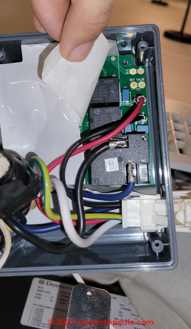
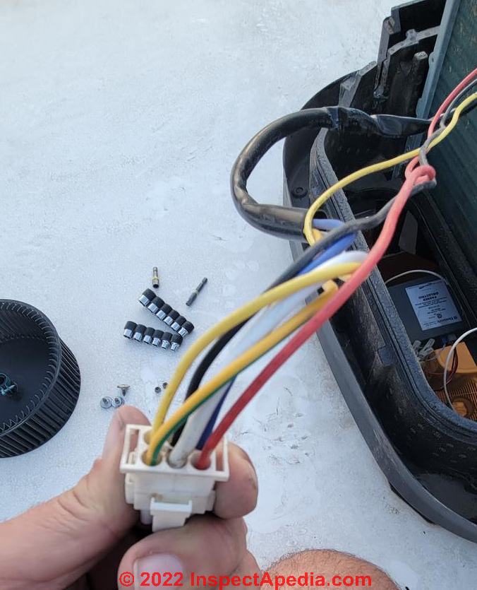
On 2022-06-25 by Tim
Dometic Brisk air RV AC, replaced fan motor and now only low speed. I tried 3 different motors thinking maybe bad windings from factory. I've swapped wires (yellow with black, red with black) and nothing. New thermostat, nothing. Please help.
On 2022-06-17 by InspectApedia-911 (mod)
@Dave,
If there is no fan one would not use the FAN terminal.
Sounds odd though. What are you wiring?
On 2022-06-16 by Dave
25mfd 370vac capacitor 3 terminals
FAN/C/HERM
can I connect C and HERM terminals and leave off the FAN Capacitor?
On 2022-05-10 by Inspectapedia Com Moderator - one wire came off the capacitor
@Joe Julian,
Please take a look at details in the article above.
You'll see that it depends ...
Are you wiring a
Start
Run
Or
Combined start / run capacitor
?
It's pretty easy ad there are either just 2 or just 3 connections. And if just 1 wire came loose there ought to be just 1 connector lacking a wire.
On 2022-05-09 by Joe Julian
The motor starting capacito09r on my 12" drill press came off during transit. One wire comes off the capacitor and goes back into the motor. The other wire attaches to the capacitor then where?
On 2022-02-12 by Inspectapedia Com Moderator - basic rules of thumb for choosing a start or run capacitor
@gprosecky,
Sure, glad to help.
See CHOOSE a START / RUN CAPACITOR, HOW TO
https://inspectapedia.com/electric/Motor_Capacitor_Selection.php
and you'll see some basic rules of thumb for choosing a start or run capacitor based on motor size and voltage.
On 2022-02-12 by gprosecky@yahoo.com
Hello I have a baldor 3h.p. # l 3610 tm that need new caps the numbers are not readable I have tried for hours on web but can not find out the size of the start and run caps that i need.Help please and thank you in advance Greg
On 2021-12-01 by Inspectapedia Com Moderator - Emerson HVAC manuals
@Jackie Johnson,
 Sorry I have no idea what a "Tun capacitor" is, but I think that's a typo.
I am guessing you meant "run capacitor" and start capacitor.
By which "side", the caps have to be on the correct terminals for Start (the start winding) and Run (the run winding) of your motor. But there's no right or wrong "side" otherwise. Surely your motor has terminals specified for its start and run capacitor connections.
At our page on information for EMERSON HVACR MANUALS
you'll find a manual for one of their scroll compressors but we are looking for other Emerson manuals to add there.
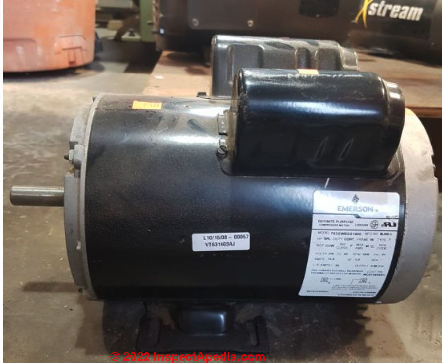
If you don't have the instruction manual and wiring diagram for your Emerson 230VAC air compressor, at our Emerson page is contact information for the company. You'll need the specific model name and number of your Emerson unit.
An example of an Emerson compressor electric motor is shown below. You'll see that there are two canisters right atop the motor - those are intended to receive the start and run capacitors for this 230VAC 5HP electric motor. Look at your motor and you should see the connecting wires or their terminals already in place.
That motor was offered for sale by https://www.coastmachineryparts.com/ and was used.
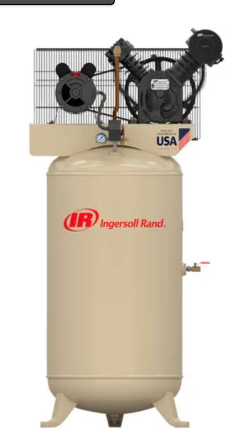
Here's a photo, for other readers, of the Emerson/Ingersoll Rand air compressor system complete
In this photo too you can see the two "ears" sown atop the compressor motor - the housings for the two capacitors.
On 2021-12-01 by Jackie Johnson
Does it matter what side you put the Tun capacitor and the start capacitor on the motor? 5 hp emerson 230 volt on a air compressor
On 2021-08-21 by inspectapedia.com.moderator - common capacitor wire connections
@Patrick,
I don't think anyone can say where those four wires go, arbitrarily,
we need to know at least
1. what is your AC capacitor serving: an outdoor compressor/condenser unit, an indoor air handler?
2. what color are the wires?
3. What is your Lennox A/C unit brand? From that we could find the service manual and wiring diagrams to be sure
BUT
Above on this page we describe ALL of the common capacitor wire connections - take a look.
On 2021-08-21 by Patrick
I have 4 wires on my Lennox AC capacitor where do they go
On 2021-04-30 by danjoefriedman (mod)
@Frank, you don't need to purchase the exact same brand of capacitor as long as you buy one of the proper size in microfarads and voltage rating. Take a look at
CAPACITOR SIZE DETERMINATION for ELECTRIC MOTORS
And you'll see how easy it is to find the correct device
On 2021-04-30 by Frank
I got a old Dean 4wire capasator wher could I purchase one
On 2020-06-25 - by (mod) - capacitor leads are brown and blue
Karen
Generally the capacitor terminals are not polarized and either wire goes on either terminal
On 2020-06-22 by Karen
Hi I am changing my capacitor Cbb60 6uf flying lead in my pool pump the leads are yellow and blue but new capacitor leads are brown and blue
which one do i treat as the yellow on as will be putting leads back into thimble thing as they are now but don't know if the brown should go where the yellow was?
On 2020-05-22 - by (mod) -
JB
Thanks for the interesting question, but I just don't know.
It is possible that there's a setting matching ampacity of the motor to the fusing of the electrical circuit to which it's connected but it is risky to guess without knowing at least * something * about the equipment.
Tell us the brand and model of your compressor and pressure washer and we can look for the service and maintenance manual that ought to answer the question.
Perhaps it's a pressure adjustment.
For example here is a SUNJOE ELECTRIC PRESSURE WASHER MANUAL [PDF] that discusses pressure adjustments and other adjustments
On 2020-05-22 by jb
Hi guys, under the cover of the on/off switch on my compressor and my pressure washer there is a tiny round adjuster with a screw driver slot in it and numbers all the way around it which appear to look like AMP numbers.. what is it what is it for and what number should it be set on? Thanks John
On 2020-05-02 - by (mod) - what if both capacitor wires are black?
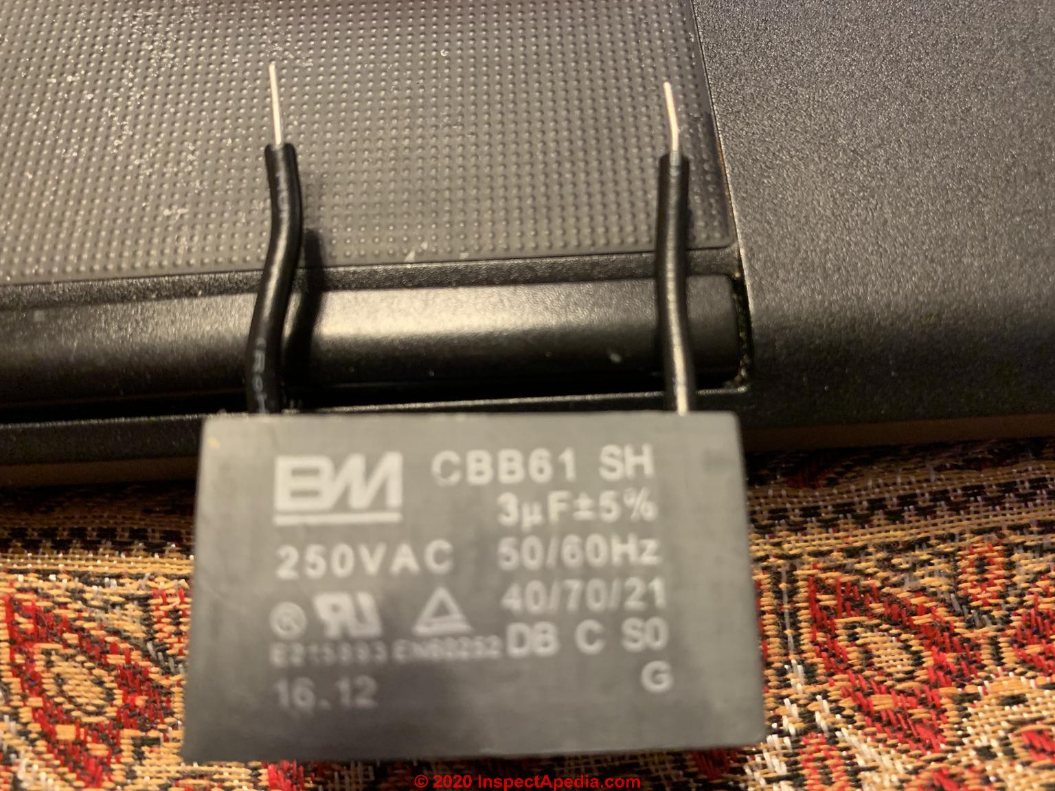 Thank you for the helpful question, Shivkumar.
In this case the 3 uf capacitor in your photo is not polarized, so you would arbitrarily connect one black wire to the COM terminal and the other to the power source of the device.
On 2020-05-02 by Shivkumar Jagasia
2.5 MF 250 V AC capacitor has both wires coloured black. How do I connect. Old defective one has one red one black
On 2020-02-26 - by (mod) -
Steve
A cap with 3 connectors is a combined start/run cap with an S and R terminal and a COM terminal. If you're converting to using separate start and run capacitors then you will simply use that original COM wire to feed separate Start (previously the S wire) and Run (previously the R wire) capacitors.
On 2020-02-26 by Steve
Replacing a compressor and old Inuit had a run cap with three connections, new compressor uses a start relay, start cap and run cap so the wiring will be different now.
Fan has brown, orange and black how are these wires connected with the new components?
On 2019-09-29 - by (mod) -
Anon
Tale a close look at the capacitor wiring terminals to see the letters marking the identity or function of each.
S - start
R- Run
C - Common
On 2019-09-29 by Anonymous
I got a 2,2 kw single fased motor that's been messed with the wires and caps.
how do I find the correct wires for starting and running caps?
please.
On 2019-07-17 - by (mod) - no ground terminal
NO ground terminal means you certainly can't connect the cap to ground.
I'd double check the wiring diagram on the Heil AC unit itself
On 2019-07-17 by Mr. R.
Replacing 45-year old run capacitor on heil air conditioner. Old capacitor had a third prong for ground. New capacitor does not. How do I connect ground on new capacitor, or do I?
On 2019-04-16 - by (mod) - Not all motors use start/run caps - Rheem blower motor?
Not all motors use start/run caps;
And if there's a single cap with just 2 wires yes that sound like a starter - else if it included run there'd be a 3rd terminal on the cap and there'd be 3 wires.
When a motor will run when given a starting spin that's a good tip-off that probably the starter cap is bad
On 2019-04-16 by Gary
I have a Rheem blower motor that just hums, won't start. motor & wiring are ok.. I can't find a start cap. only a run cap .I looked at wiring & only shows a run cap. with 2 brown wires tapped to motor. could this be my start cap. if so I tried a new one, still hums . will run if you spin motor.any ideas?
...
Continue reading at EXAMPLE of CAPACITOR REPLACEMENT or select a topic from the closely-related articles below, or see the complete ARTICLE INDEX.
Or see MOTOR CAPACITOR WIRING FAQs - questions & answers about wiring up start or run capacitors posted originally at this page
Or see these
Recommended Articles
- ANALOG VOMs & MULTIMETERS
- BASIC ELECTRICAL TESTS for BURNED OUT COMPRESSOR MOTORS
- CAPACITOR TYPES, for MOTORS
- CAPACITORS for HARD STARTING MOTORS
- CAUSES of HARD STARTING ELECTRIC MOTORS
- CAPACITOR SIZE DETERMINATION for ELECTRIC MOTORS
- COPELAND ELECTRICAL HANDBOOK [PDF]
- HARD STARTING COMPRESSOR MOTORS
- HOW a STARTING CAPACITOR WORKS
- HOW to TEST the MOTOR to ID TERMINALS
- LOCATE the STARTING CAPACITOR
- MOTOR CAPACITOR WIRING GUIDE
- STARTING CAPACITOR SAFETY
- TEST a MOTOR START or RUN CAPACITOR
- DMM DIGITAL MULTIMETER HOW TO USE
- ELECTRIC MOTOR CENTRIFUGAL SWITCH or PTC PRD
- ELECTRIC MOTOR DIAGNOSTIC GUIDE - home
Suggested citation for this web page
MOTOR CAPACITOR WIRING GUIDE at InspectApedia.com - online encyclopedia of building & environmental inspection, testing, diagnosis, repair, & problem prevention advice.
Or see this
INDEX to RELATED ARTICLES: ARTICLE INDEX to ELECTRICAL INSPECTION & TESTING
Or use the SEARCH BOX found below to Ask a Question or Search InspectApedia
Ask a Question or Search InspectApedia
Try the search box just below, or if you prefer, post a question or comment in the Comments box below and we will respond promptly.
Search the InspectApedia website
Note: appearance of your Comment below may be delayed: if your comment contains an image, photograph, web link, or text that looks to the software as if it might be a web link, your posting will appear after it has been approved by a moderator. Apologies for the delay.
Only one image can be added per comment but you can post as many comments, and therefore images, as you like.
You will not receive a notification when a response to your question has been posted.
Please bookmark this page to make it easy for you to check back for our response.
Our Comment Box is provided by Countable Web Productions countable.ca
Citations & References
In addition to any citations in the article above, a full list is available on request.
- [2] "Motor Start and Run Capacitors", AFCAP (African Capacitors Limited), web search 08/05/2011, original source: http://www.afcap.co.za/manual/Part2.pdf
- George Fazio, reader, contributed comments on failed starter capacitor diagnosis by noting the bulged capacitor ends. 09/25/2009
- Troubleshooting Compressor Problems," Henry Puzio, Fuel Oil & Oil Heat with Air Conditioning Magazine, June 1993, p. 39
Tom Morris, Engineer, capacitor discussion and correction to the original data. Email to D Friedman 5/29/2006 - Thanks Tom for critical editing. The text above explaining about capacitors was suggested by Mr. Morris. The original text of the 1993 compressor diagnosis article had the resistance explanation backwards. - Thanks to reader Diane McGivney for asking about air conditioner compressor motor starting capacitor costs and typical air conditioner service call fees - (May 2010)
- Thanks to reader James Oiler for reporting on the replacement of a heat pump starter capacitor, August 2010.
- Modern Refrigeration and Air Conditioning, A. D. Althouse, C.H. Turnquist, A. Bracciano, Goodheart-Willcox Co., 1982
- Principles of Refrigeration, R. Warren Marsh, C. Thomas Olivo, Delmar Publishers, 1979
- "Air Conditioning & Refrigeration I & II", BOCES Education, Warren Hilliard (instructor), Poughkeepsie, New York, May - July 1982, [classroom notes from air conditioning and refrigeration maintenance and repair course attended by the website author]
- Refrigeration and Air Conditioning Technology, 5th Ed., William C. Whitman, William M. Johnson, John Tomczyk, Cengage Learning, 2005, ISBN 1401837654, 9781401837655 1324 pages
- In addition to citations & references found in this article, see the research citations given at the end of the related articles found at our suggested
CONTINUE READING or RECOMMENDED ARTICLES.
- Carson, Dunlop & Associates Ltd., 120 Carlton Street Suite 407, Toronto ON M5A 4K2. Tel: (416) 964-9415 1-800-268-7070 Email: info@carsondunlop.com. Alan Carson is a past president of ASHI, the American Society of Home Inspectors.
Thanks to Alan Carson and Bob Dunlop, for permission for InspectAPedia to use text excerpts from The HOME REFERENCE BOOK - the Encyclopedia of Homes and to use illustrations from The ILLUSTRATED HOME .
Carson Dunlop Associates provides extensive home inspection education and report writing material. In gratitude we provide links to tsome Carson Dunlop Associates products and services.
 | HOME | ABOUT | ASK a QUESTION | CONTACT | CONTENT USE POLICY | DESCRIPTION | POLICIES | PRIVACY | |
| © 2024 - 1985 Publisher InspectApedia.com - Daniel Friedman | |||||||||