
InspectAPedia® FREE Encyclopedia of Building & Environmental Construction, Diagnosis, Maintenance & Repair |
Question? Just ask us! InspectAPedia
|
 Wire-to-Connector Area Differences on Receptacles & Switches
Electrical connector wire-contact area differences on electrical receptacle and switch wiring connectors:
Push-in type back-wired electrical receptacles & switches have significantly less electrical contact area than other connectors on these devices. Pressure or torque forces vary as well.
This article describes differences in electrical-wire to device connector surfaces between push-in type backwire connectors, compression plate connectors, and binding head screw connectors, all of which are found on many electrical receptacles and switches.
These area differences can be significant, up to ten times variation in surface area. Small surface area and possibly other properties of push-in back-wired electrical receptacles and switches may explain some field failures reported on those devices.
This article series explains receptacle types, receptacle grounding, connecting wires to the right receptacle terminal screws, electrical wire size, electrical wire color codes, and special receptacles for un-grounded circuits.
InspectAPedia tolerates no conflicts of interest. We have no relationship with advertisers, products, or services discussed at this website.
Variations in Wire-to-Connector Contact Area on Three Electrical Receptacle Connector Types
Introduction: contact areas sizes vary among electrical receptacle connector types
At BACKWIRED RECEPTACLE FAILURE PHOTOS where we discuss the key factors in the decreasing reliability and and increasing risk of push-in backwire electrical receptacle wire connections we emphasize the inherent weakness of the spring-clip connector.
But differences in actual contact area between the wire and the connector may be factors that increase the risk of a connector failure, overheating, or fire.
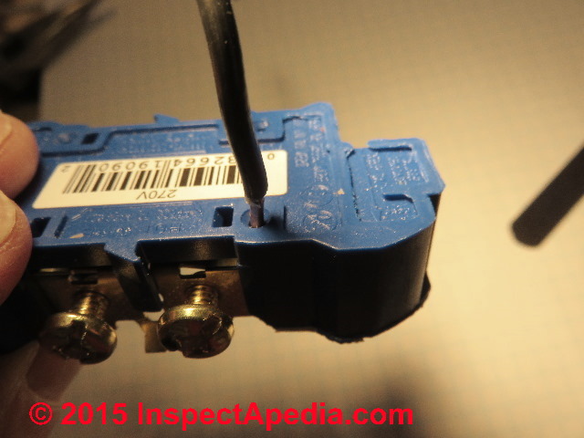
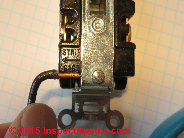
In this article we illustrate the typical connector used in some receptacles and switches that accept a simple push-in connection usually found on the rear of the device.
The rectangular opening is used to release an installed wire. Simple screw terminals are also visible in the lower left of the photo.
[Click to enlarge any image]
This article compares the approximate size of contact areas between an electrical wire and the connector surfaces in an electrical receptacle across three different connector designs:
- Push-in back-wired electrical receptacles
- Binding head screw connector on electrical receptacles
- Insert-in screw-clamp type back wired or side-wired electrical receptacles
This article concludes that
On an electrical receptacle or switch the binding head screw wire contact area offers about four times the contact surface as a perfectly-made push-in backwired receptacle or switch connection, and if the wire is bent in a push-in connection, the binding head screw offers nearly ten times the contact area as the push-in device.
Why do we care about the size of the contact area between an electrical wire and the connectors on the device such as a receptacle or "outlet" or a light switch ?
Because it is both true in theory and appears true in field reports that a smaller or more fragile electrical contact between the wire and the device can increase the risk of an electrical failure, overheating, and possibly building fires.
In concept, if we keep voltage and current flow (120V and up to 15A in the electrical receptacle connections examined here) then a smaller contact between connections may be expected to generate more heat. The circuit breaker or fuse protecting a circuit is intended to avoid un-safe overheating but an electrical connector that uses minimal contact area may be at increased risk of field failures.
See DEFINITIONS of ELECTRICAL TERMS - or go directly
to DEFINITION of ELECTRICAL RESISTANCE, OHM's LAW in that article for details.
There you'll read that Ohm's law is basically a measure of resistance which in turn is a measurement of the heat that will be generated by an electrical wire (or contact) that is carrying a given current (amps or load).
At above left we illustrate a #14 solid copper wire being pushed into the backwire opening of a common electrical receptacle. The wire has not been pushed fully into the connection as I wanted to show the diameter of the wire entering the push-in connector opening.
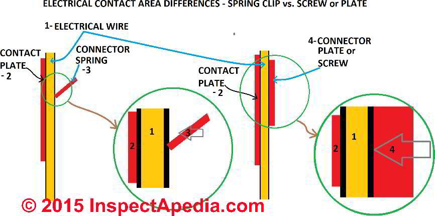
Our page top illustration of a spring-clip type back-wired push-in receptacle connection comparing that to a pressure plate or screw connection is discussed in detail separately
at BACKWIRED DEVICE SPRING CLIP DETAILS.
Article Contents
- RECEPTACLE WIRE-TO-CONNECTOR CONTACT AREA SIZES
- ELECTRICAL CONTACT AREA: PUSH-IN SPRING CONNECTOR
- ELECTRICAL CONTACT AREA: BINDING HEAD SCREW CONNECTOR
- ELECTRICAL CONTACT AREA: PRESSURE PLATE CONNECTOR
- ELECTRICAL WIRE-to-CONNECTOR CONTACT AREA SUMMARY TABLE
- REAL ELECTRICAL CONTACT & RESISTANCE: AREA, FORCE, OTHER FACTORS
- ELECTRICAL SCREW CONNECTOR TORQUE-FORCE
- ELECTRICAL SCREW CONNECTOR TORQUE DAMAGE
Estimated wire-to-connector contact area on a push-in electrical connector on a receptacle
Measurements of Possible Contact Surfaces on #14 Electrical Wire and the Surfaces of a Push-In Electrical Connector on an Electrical Receptacle
Below measurements indicate the approximate length of contact area between an electrical wire and the surfaces in a push-in backwire connector used in a typical electrical receptacle. Keep in mind this is only the length of contact area.
The actual contact area expressed in square mm will be slightly greater than the length depending on the width of actual physical contact between the rounded wire surface and the relatively flat area of the contact plate or the contacting edges of the leaf spring.
Besides the actual contact area in mm2, the force of the spring against the wire is a critical factor in the quality and reliability of the wire-to-connector contact, and it certainly will be a factor in the depth of notch cut into the wire by the end of the leaf spring during and after wire insertion.
See WIRE-TO-CONNECTOR FORCE COMPARISONS for a comparison of the connection force of the spring clip connector with the force exerted by a binding head screw connector.
Above we show that the approximate width of the end of the leaf-spring that pushes against a back-wired push-in wire is 3mm.
The actual contact width of the end of the spring with the wire will depend on how precisely the wire radius matches the spring notch, the depth of the cut that the spring causes into the wire, and perhaps something else I've not considered.
Above you see that the width of the contact plate against which the push-in backwire receptacle connector forces the wire is about 9mm, possibly reduced a bit by the notch cut out of that surface. As we discuss in this article, the actual wire contact with the contact plate may be significantly reduced if the wire itself is not very straight.
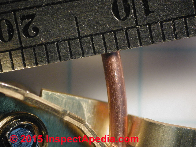
Above is a close-up photo of a #14 copper wire against a millimeter scale.
The actual wire diameter of #14 copper wire can vary among manufacturers and wire types.
At SE CABLE & BRANCH CIRCUIT WIRE SIZES vs AMPS we give the typical diameter of #14 copper wire as 2.05 to 2.32 mm or about 0.081 - 0.092 inches.
Also see ELECTRICAL WIRE TYPES CODES USES
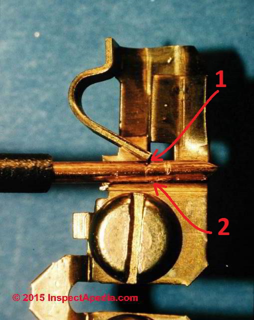
Using the measurements above, ignoring the effects of spring force against the wire, just considering the length of wire-to-connector contact here are some rough contact area estimates & calculations for a back-wired push-in electrical connector such as the receptacle connector shown in the photograph just above:
- 1.5mm = Length of contact surface of wire under the notched end of the leaf spring - red arrow A above.
- 0.125 mm = combined width of the two surfaces cut into the copper wire by the end of the round-notched leaf spring
- 0.1 mm = width of the contact surface of the wire against the contact plate
- 7.0mm = length of contact surface of wire against the contact plate - red arrow B above.
Note that this 7mm estimate is about half the length of bare wire indicated by the strip gauge on the back of the receptacle case. The "strip gauge" molded into the rear of the receptacle and shown below indicates a 14-15mm strip length (about 3/8") for the wire to be used with this device.
But it is the size of the contact plate (shown above) that determines the maximum possible wire contact along its length when pushed into the back-wired connector.
That length (in this receptacle) was between 8 and 9 mm, and observation when I inserted a wire showed that by no means did the wire actually contact all of the available connector surface.

Push-in connector wiring contact area for a straight copper wire
CASpring = contact area of wire to the end of the leaf spring
- CASpring = 1.5 x 0.125 = 0.1875mm2
CAPlate = contact are of wire to the contact plate
- CAPlate = 7.0 x 0.1 = 0.7 mm2
CAT = Total contact area for a relatively-straight copper wire in the connector
- CAT = CASpring + CAPlate = 0.1875 + 0.7 = 0.8875 mm2 for a straight electrical wire.
- CATotal Push-In Connector = 0.8875 mm2 for an electrical wire that is straight
Note: these are estimated contact surface areas. An actual physical measurement of contact area may be possible using other methods.
Push-in connector wiring contact area for a curved or bent copper wire
- CASpring = 1.5 x 0.125 = 0.1875mm2
- CAPlate = 2.0 x 0.1 = 0.2 mm2
- CAT = CASpring + CAPlate = 0.1875 + 0.2 = 0.3875 mm2 for a bent or curved electrical wire end
- CATotal Push-In Connector = 0.3875 mm2 for an electrical wire that is bent
Percent reduction in back-wired electrical connector contact area when the electrical wire has been bent or curved©
- CAReductionPercent = (1 - 0.3875 / 0.8875) x 100 = 56%
Discussion: these are estimated wire-to-connector contact surface areas.
An actual physical measurement of contact area may be possible using other methods. Additional important effects of the condition of the wire and connector surfaces such as due to corrosion, prior arcing, oxidation, have not been considered here.
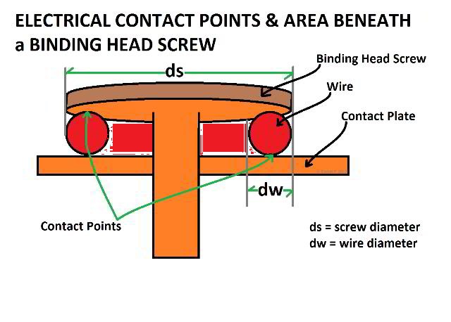
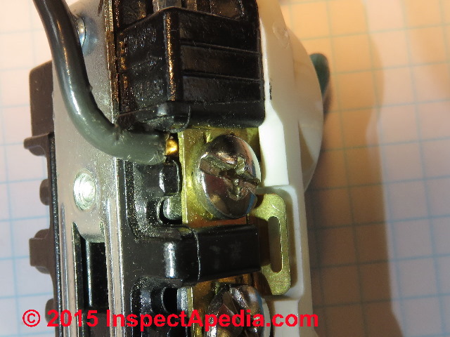
Estimated wire-to-connector contact area for Binding Head Screw Connectors.
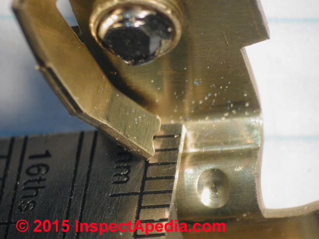
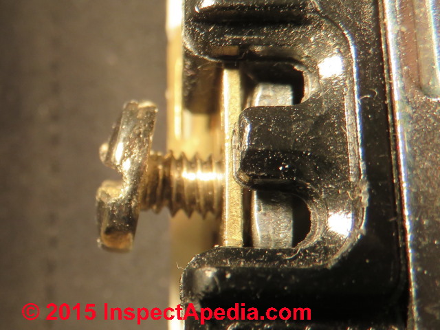
A similar measurement and contact area estimates can be performed for the contact areas beneath a binding-head screw (photo below) that is an alternative connector for push-in backwired devices.
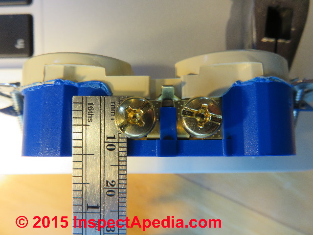
You'll note that the binding head screw outer diameter is between 8 and 9 mm for the product shown, an Eaton 2427AD 15A 125V rated electrical receptacle that was purchased at a Home Depot store for $0.69 U.S.D. in October of 2015.
Here are some rough calculations, again ignoring the effects of differences in contact force between that imposed by the leaf spring of a push-in backwired connector and the force imposed by a binding head screw or screw-operated compression plate connection of electrical wires in a receptacle or switch.
Electrical Wire Contact Area in a Binding Head Screw Connector
[Click to enlarge any image]
Using a duplicate of the same electrical receptacle model as was employed above for measuring the areas beneath the head of the side connection "binding head screw" we found:
- CAScrew = maximum plausible contact area of wire to the under-side of the screw = (mm Screw outer circumference - wire thickness)
Since the wire must be under the screw to be secure we assume that it is under the screw but as close to the screw outer edge as will leave the outermost edge of the wire "under" the screw head, as illustrated above. For maximum possible contact area (and to simplify calculations) we assume that the wire makes a full circle (which it won't). The diameter of the full circle of electrical wire will be calculated as follows:
Screw-head diameter minus one wire thickness
(As the wire contact point will be at half of the wire thickness under the head at opposing sides of any diameter measurement point).
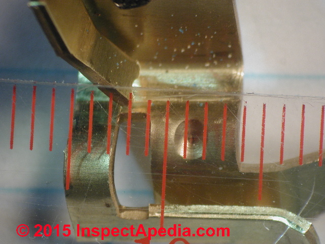
- Screw head diameter measurement = 8mm to 9mm (approximate)
- Wire thickness (by measurement) = 2.15mm
- Wire contact circle diameter at the point of contact with the screw or contact plate = 8 - 2.15 = 5.85 mm.
- Wire contact circle radius = 1/2 diameter = 2.93 mm
The total contact area of wire under the screw head as well as on the contact plate below the screw head will each be calculated as the circumference of the wire circle x the estimated contact surface width at the point of contact between the screw head and the wire or the contact plate and the (round) wire surface.
Convert wire circle diameter to circumference: Circumference = 2 π r
- Wire contact circle circumference = 2 x 3.1416 x 2.93 = 18.4 mm
- Wire contact surface area width = 0.1 mm
Total electrical wire contact surface area below the binding head screw is then contact length (circumference) x contact width for both the screw underside and the surface of the contact plate below the wire.
Electrical wire contact area in a binding head screw connection including both screw head and pressure plate is then calculated as
- CAScrewHead mm2 = 18.4 x 0.1= 1.84 mm2
- CAPressurePlate mm2 = 18.4 x 0.1= 1.84 mm2
- CATotal Binding Head Screw mm2 = 3.68 mm2
Estimated wire-to-connector contact area for Pressure-Plate Type Screw Connectors.

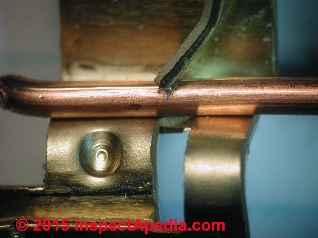
A similar measurement and contact area estimates can be performed for compression plate back-wired electrical receptacles - a (probably) better-performing design alternative to push-in backwired devices. At above left you can see a typical pressure-plate screw-clamp type electrical wire connector on an electrical receptacle.
Above is a #12 copper wire against the manufacturer's wire-strip gauge on the back of this device, and below we show a measurement of the length of the strip gauge as 9 mm.
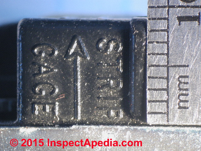
The wire strip gauge indicator found on the back of a typical electrical outlet or switch provides for stripping about 15mm of insulation from the wire. Estimating that about 13 mm of wire is ultimately pinched between two flat pressure plates that are squeezed over the wire, we can calculate the approximate electrical wire to connector contact area as follows:
CATotal Compression Plate Connector mm2 = 2 x wire contact length x wire contact width
CATotal Compression Plate Connector mm2 = 2 x 9mm x 0.1 mm
CATotal Compression Plate Connector mm2 = 1.8 mm2
This makes sense in that the total wire length of a loop of wire under a binding head screw will surely be longer than the straight length of stripped wire pushed into a back-wired device.
Summarizing the estimates of contact area between the electrical wire and these three different types of electrical receptacle wire connection devices
Summary Table of Electrical Wire to Connector Contact Areas
Summary of Approximate Electrical Wire Contact Surface Area in Electrical Receptacle & Switch Connectors |
||
| Connector Type | Estimated Contact Area in mm2 | Comments1 |
| Push-in Backwired Connector | CATotal Push-In Connector = 0.8875 mm2 | Assuming the inserted wire is straight |
| Push-in Backwired Connector | CATotal Push-In Connector = 0.3875 mm2 | For an electrical wire that is bent or curved |
| Insert-in Backwired Pressure-Plate / Clamp-type Screw Connector | CATotal Compression Plate Connector mm2 = 1.8 mm2 | Assuming the inserted wire is straight |
| Wire loop under binding head screw | CATotal Binding Head Screw mm2 = 3.68 mm2 | Assuming a perfect circle of wire |
Notes to the Table Above
1. The effects of contact force on electrical resistance between the wire and its contact on an electrical switch or receptacle are not included here
2. Because my assumption that the wire under a binding head screw is a perfect circle may slightly over-state the wire contact area, I used 8mm rather than 9mm as the screw head diameter.
3. On an electrical receptacle or switch the binding head screw wire contact area offers about four times the contact surface as a perfectly-made push-in backwired receptacle or switch connection, and if the wire is bent in a push-in connection, the binding head screw offers nearly ten times the contact area as the push-in device.
The significance of these differences in wire-to-connector contact area is significantly affected as well by differences in force exerted against the wire among these connectors and may be affected by differences in the condition of the wire with which the connection is being made.
These estimates are based on calculations given in the article above and assume a wire contact area width along the wire against a plate or screw of 0.1mm using #14 copper wire.
The extent of flattening of the surface of the wire due to compression by a connecting screw will affect this estimate as may other wire conditions such as re-using old, previously-bent or twisted electrical wiring in a re-wire or device replacement repair operation.
As we discuss just below, the true contact area and thus electrical resistance of the connection is not so simple.
What is the Real Area of Electrical Contact Between a Wire and a Connector:
Contact Resistance is a function of (force x micro-contact points x other factors such as oxide resistance)
Watch out: as electrical engineering experts point out in numerous research articles (some cited here), the effectiveness of an electrical contact derives from the combination of the size or area of the contacting conducting surfaces and the force applied to their contacting surfaces.
The table above describes only contact area size for different electrical connectors on electrical receptacles (and some switches). Below at left is the spring-clip connector of a push-in backwire electrical receptacle. Below at right is a binding-head screw on the side of an electrical receptacle.

[Click to enlarge any image]
Research (cited below) points out that the actual physical contact and thus electrical current flow between an electrical wire and the electrical connector surface actually occurs through numerous microscopic points of contact. (Greenwood 1966 et als).
Those authors make a clear distinction between the "constriction resistance" and the "real area of contact" in electrical devices and cite the Holm radius and Holm's equation that provides "... a method of obtaining a practical estimate of the interaction term ..." to describe clusters of contact points.
Below is a screw-clamp or pressure-plate type connector on an electrical receptacle.
This connection combines back-wiring and stronger connector force between wire and connector than seems likely from the spring type connector shown at above left.
Greenwood (1966) points out that "Whenever we have a reasonably large number of not-to-small contacts, the self-resistance term becomes small and the constriction resistance is close to that observed if the entire area of the cluster were in electrical contact". [Emphasis ours].
The author continues to note that in addition to contact area (and force) as factors in electrical resistance, oxide films or coatings must be considered, and makes this interesting remark in section 4.3 of the article I cite:
The mechanical area of contact [between a wire and an electrical connector] is often very much less than that deductible from bulk properties. - Op. Cit.
Separately at WIRE-TO-CONNECTOR FORCE COMPARISONS we discuss obvious differences in the wire-to-connector contact force available in these three connector types, of which it appears that push-in back-wired spring-type connectors exert considerably less force than a properly-tightened binding head screw or clamp and pressure-type screw connector. Also see Tismit (1998) and Park (2002) cited below.
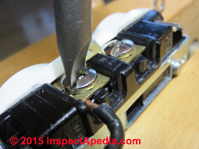
Estimated Pressure of Binding Head or Pressure Clamp Screw to Copper Wires
At AlumiConn TORQUE TESTS we quote expert advice from King Innovation electrical engineers who said that when using that company's AlumiConn™ aluminum wire repair connectors useful for pigtailing aluminum wire ends to copper:
Torque Recommendation: 15 inch-pounds when connecting ... All Solid or Stranded Copper conductors
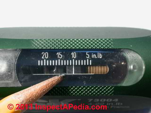
I did some further crude experiments using the same S.K. torque screwdriver provided by King Innovations. This tool has an adjustable torque setting range of 4 to 22 inch-pounds of torque.
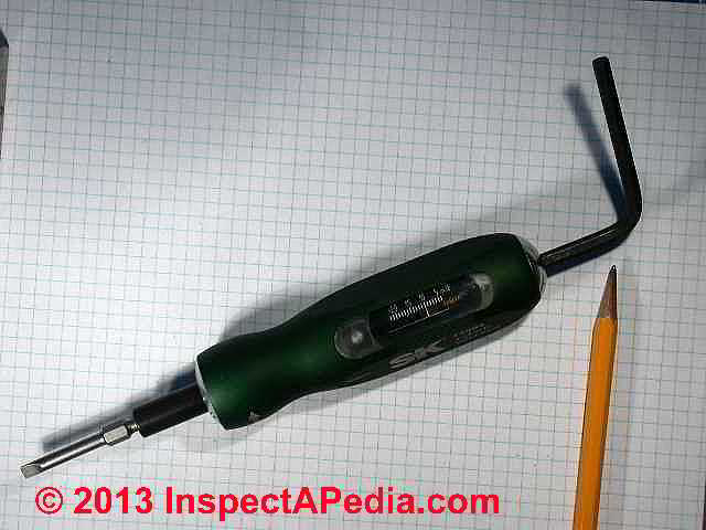
[Click to enlarge any image]
I tightened a #14 solid copper wire in the pressure clamp of a modern back-wired receptacle, observing just how physically difficult it was to turn the screw to 22 inch-pounds.
I started with the tool set at 15 inch-pounds of torque, tightened the screw, then re-set the tool to its maximum torque - 22 inch-pounds and tightened the clamp screw again.
I selected a flat-bladed screwdriver bit that was the biggest that would fit into the screw slot - thus minimizing slippage. (Slippage occurred anyway.) When installers use power tools to driver up screws on electrical devices they usually use a Phillips-driver bit and apply down-pressure onto the screw while turning it.
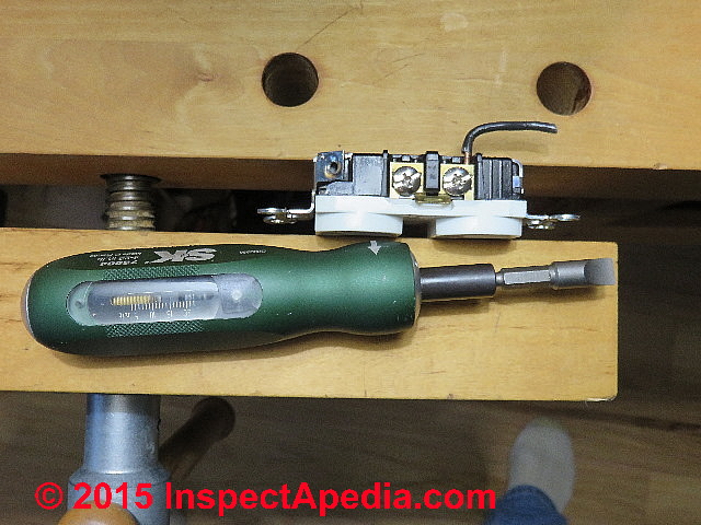
For these tests I mounted the electrical receptacle in a wooden vise (above), providing the best feasible position for applying considerable hand force to tighten its screw. In normal electrical wiring in the field nobody tightens wires onto a receptacle that is held in a vise.
And nobody - at least nobody normal - even owns an SK torque-measuring screwdriver. You won't find this tool at most electrical supply stores. My opinion is that I was able to apply more torque with this method than would normally be applied in the field. Modest damage to the flat-blade screwdriver slot of the screw is shown below.
It was physically difficult to turn the binding head screw on the receptacle to 22 inch-pounds of torque, and even 15 pounds was a bit of a challenge. My opinion is that
most by-hand field-tightened electrical screws used on receptacles and switches are going to be at 15 pounds of torque or less.
power-tool-tightened electrical screws on electrical receptacles and switches is likely to be at 15 pounds of torque or more and is limited in part by the position of the device being tightened and the ability of the installer to hold it in place.
Researchers determining the nature of actual true electrical contact between surfaces and the concomitant resistance and connection quality probably have to take more accurate pressure measurements.
Patents that I surveyed referred to "exceptionally high torques" available when tightening screws using power tools but did not include specific measurements. (Jasch 2001).
I did not test the torque necessary to un-screw the electrical receptacle screw in the pressure clamp connector as the S.K. device I used provides torque only in the tightening direction. However we know that considerably more torque would be used to loosen a tightened fitting than to turn it tight in the first place. (Simonin 1992).
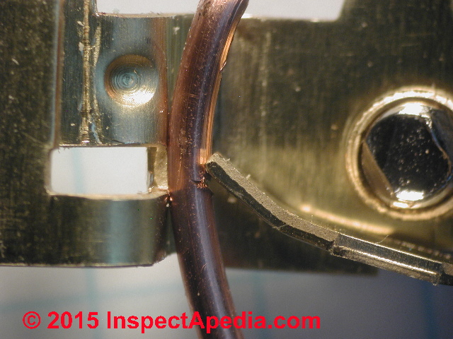
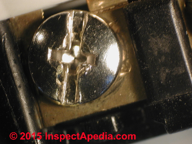
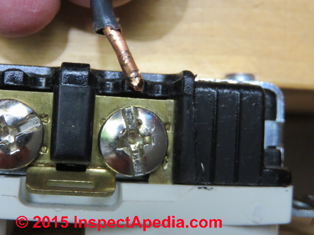
Torquing Damage to Copper Electrical Wire, Electrical Connectors & Electrical Connector Screws on a Back-Wired Receptacle
After tightening the heck out of the pressure-plate electrical connector on the receptacle shown above (Heck = 22 inch-pounds of torque), it was suggestive to consider these questions:
- How difficult is it to simply pull the wire out of the receptacle connector?
In an entirely subjective test, pulling straight out on the copper wire to try to remove it (without loosening the screw) felt about as difficult as doing the same test on a spring-clip backwired device.
Note that this is a withdrawal effort and its not measuring the contact quality differences among those two devices. Click to enlarge the image below to view the gouges imparted to the copper wire by twisting it and pulling it out of the connector.
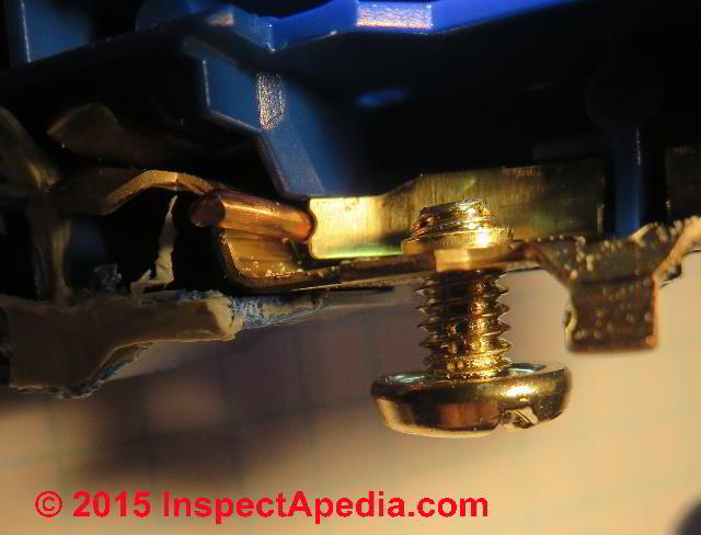
- Is there visible damage to the electrical connector screw from higher-torque application?
Yes there was some subtle thread damage visible to the electrical connector screw whose heck had tightened out-of.
The threads were gouged near the screw head, and more interesting, the screw head was actually bent askew by the forces applied when the screw clamp is tightened against a single wire.
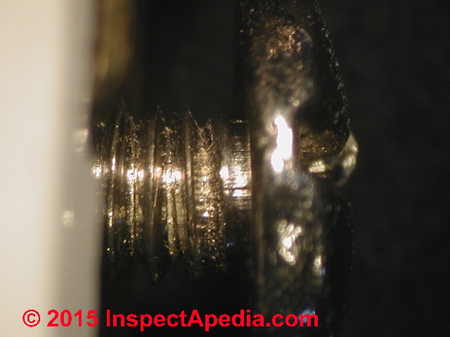
What does this visible damage to the receptacle connector screws mean?
- It is possible to damage the connector when applying high torque by hand and perhaps more so when tightening these screws using a power driver.
- OPINON: this damage may reduce the reliability of the connections or the reliability of the connections when wires are removed and re-installed.
References on electrical contact resistance, heat, and performance for residential electrical wiring & devices
- Aronstein, Jess, [Personal communication, J.A. to the editor (Daniel Friedman)], 25 October 2015. Dr. Jess Aronstein, protune@aol.com is a research consultant and an electrical engineer in Schenectady, NY. Dr. Aronstein provides forensic engineering services and independent laboratory testing for various agencies. Dr. Aronstein has published widely on and has designed and conducted tests on aluminum wiring failures, Federal Pacific Stab-Lok electrical equipment, and numerous electrical products and hazards.
See ALUMINUM WIRING BIBLIOGRAPHY and FPE HAZARD ARTICLES, STUDIES and
also BACK-WIRED ELECTRICAL DEVICES for examples.
Dr. Aronstein is a frequent contributor to InspectApedia.com and a personal friend of the publisher/editor. His contact information is
at TECHNICAL REVIEW COMMITTEE MEMBERS
- BACK-WIRED ELECTRICAL DEVICES - how to back wire an electrical receptacle (outlet) safely & which types of back-wired receptacles are unsafe. Some back-wired devices perform poorly in the field and risk circuit failure, overheating, or fire. Others may be fine. The distinction is described in this article.
- Greenwood, J. A. "Constriction resistance and the real area of contact." [PDF] British Journal of Applied Physics 17, no. 12 (1966): 1621.
Abstract. The relation between the area of contact and the constriction resistance which holds for a single circular contact spot is widely used in electric contact theory, although the normal node of contact is by a large number of microcontacts.
A method of finding the resistance of a cluster of microcontacts is derived, and it is shown that the resistance may be regarded as the sum of the parallel resistance of the microcontacts and an interaction term often related to the extent of the cluster and not to the number or size of the individual contacts. The resistance is often close to that found by assuming that the entire area covered by the cluster is a single conducting spot.
The known agreement between areas of contact found from resistance measurements and by other methods is therefore puzzling-until it is realized that the other methods also give only an apparent area: the real area of contact in, for example, a Brinell indentation is a small fraction of the area of the indentation. Thus from the point of view of electric contact theory the system is self-consistent, although the real area of contact is now seen to play no part in it: the implications for the theory of friction are more profound. - Houzé, F., R. Meyer, O. Schneegans, and L. Boyer. "Imaging the local electrical properties of metal surfaces by atomic force microscopy with conducting probes." Applied physics letters 69, no. 13 (1996): 1975-1977. Abstract:
A promising technique capable of performing localized resistance measurements over a surface is presented using a modified commercial atomic force microscope with a conducting probe.
Its overall purpose is to obtain simultaneous cartographies of surface roughness and local resistance within a given microscopic area of a sample with nanometer scale resolution.
Although an elaboration of suitable probes remains an ongoing problem, convincing images of some metal surfaces that reveal occasionally surprising features have already been obtained. Calculations performed from measurements have allowed us to clarify the mechanical nature of the tip/surface nanocontact and hence to determine the most probable transport process according to the range of resistance considered. - Jasch, Michael. "Power tool having a receptacle for securing a tool." U.S. Patent 6,796,888, issued September 28, 2004.
- Kogut, L., and K. Komvopoulos. "Electrical contact resistance theory for conductive rough surfaces." Journal of Applied Physics 94, no. 5 (2003): 3153-3162.
A general electrical contact resistance (ECR) theory for conductive rough surfaces was derived from first principles. The analysis is based on fractal geometry for the surface topography description, elastic-plastic deformation of contacting asperities, and size-dependent constriction resistance of microcontacts.
Relations for the ECR in terms of contact load and apparent contact area are obtained for isotropic, homogeneous, conductive surfaces with known material properties and surface topography. Useful design guidelines for electrical contacts are extracted from the numerical results.
A general relation between the dimensionless real contact area and the dimensionless ECR is introduced for lightly loaded contacts that depends only on the electron mean free path. Approaches for determining the surface roughness, material properties, and real contact area are discussed in the context of relatively simple ECR measurements. - Park, J. G., S. H. Lee, B. Kim, and Y. W. Park. "Electrical resistivity of polypyrrole nanotube measured by conductive scanning probe microscope: the role of contact force." Applied physics letters 81, no. 24 (2002): 4625-4627.
- Roebuck, Randal D., and Salvatore P. Rizzo. "Non-destructive interconnect system for semiconductor devices." U.S. Patent 5,468,158, issued November 21, 1995.
- Rothweiler, Richard C., "Torque adjustment for power driven tools." U.S. Patent 2,854,831, issued October 7, 1958.
- Shen, Zejun, Li Hao, Peng Zuo, and Jiansheng Yuan. "Analysis of Approaches for Modeling the Contact Resistance on Conductor Interface by the Finite Element Method." Session 2P8: 370.
Abstract— There may be an additional contact resistance on the interface of conductor regions caused by the change of material property, i.e., the resistivity. The simulation of the contact resistance is very important to get the Joule-heat losses of the conductors. However, it is difficult or impossible to model and calculate the contact resistance by using the traditional finite element method (FEM).
A new method to model the contact resistance has been proposed in this article, with the help of the contact element in FEM software ANSYS. The contact element meshes the interface between conductors directly. With the parameter of “surface conductivity”, equations can be set up to couple the value elements of the conductors. We have implemented the simula- tion of contact resistance on the interface of different shape regions.
Some examples of contact resistance calculation under different contact conditions are given and compared to those given by other methods. It is shown that using the contact element of ANSYS can model the contact resistance more easily and accurately, with a great advantage over other methods. - Simonin, Jacques. "Device for screwing and unscrewing screws, bolts and nuts." U.S. Patent 5,158,354, issued October 27, 1992.
- Timsit, Roland S. "Electrical contact resistance: properties of stationary interfaces." In Electrical Contacts, 1998. Proceedings of the Forty-Fourth IEEE Holm Conference on, pp. 1-19. IEEE, 1998.
The paper reviews the dependence of electrical contact resistance on the shape and dimensions of /spl alpha/-spots and on the magnitude of the mechanical contact load. The range of validity of the classical voltage-temperature relation for electrical contacts is also examined.
The paper describes experimental evidence of breakdown of the classical electrical theory when /spl alpha/-spots become too small. One of the interesting and useful properties of relatively small /spl alpha/-spots is that they are subject to large surface stresses. These stresses induce /spl alpha/-spot growth. - UL 486A - 486B STANDARD for SAFETY [PDF] (2013) retrieved 2019/11/20 original source: http://www.pts.ir/panel/images/post/43vdc1zrlyUL%20486a-486b-2013.pdf
- Vogler, M., and S. Sheppard. "Electrical contact resistance under high loads and elevated temperatures." surfaces 9, no. 10 (1993): 11. [Appearing in a supplement to The Welding Journal, June 1993. Retrieved 28 Oct 2015, original source: https://app.aws.org/wj/supplement/WJ_1993_06_s231.pdf
- Also seeReferences or Citations
Reviewer Comments
Heat is the big problem in electrical contacts
 Power dissipated or heat produced is proportional to the square of the current. Because of the following formula, even a small resistance can cause a lot of heat when a large amount of current is being drawn.
Your issue is that the contacts should not reflect any resistance. Small contact area means more resistance. Sorry but I do not know the details of ohms per contact area. (My guess is that there is more to it than just contact area such as contact pressure or surface oxidation of the wire.)
Power (heat) = current x voltage
since voltage = current x resistance
Power (heat) = current x current x resistance or P=I2r
Any small amount of resistance can produce significant heat when used in an environment where there is heavy current demand. e.g. vacuum cleaners, toasters, microwaves, etc. The increased heat at the contact point is probably what causes the deterioration of the connection over time.
Are those little springy things (photo at left) really copper? I would not have thought that copper would have the needed strength. This especially if there is any heat being produced. - 11/8/2015 Paul Galow, E.E.
Mr. Galow is a frequent contributor to InspectApedia.com and a personal friend of the publisher/editor. His contact information is
at TECHNICAL REVIEW COMMITTEE MEMBERS
Author replies:
Thanks Paul. The push-in backwire spring assembly looks like copper but I suspect it's an alloy. While I have not measured it accurately, just the subjective experience of the force necessary to push a #14 copper wire into the connector argues that there is a palpably-strong spring force involved. Just how that spring force will be maintained if a wire is later removed and re-inserted is not known.
Aronstein as well as researchers I cited above emphasize that while contact area is important in understanding electrical connectors, the force with which the two surfaces are pressed together is critical as well.
The article above discusses only the comparative areas of different electrical contacts used in receptacles and some switches and finds that even before considering force, the areas vary considerably.
Reader Comments, Questions & Answers About The Article Above
Below you will find questions and answers previously posted on this page at its page bottom reader comment box.
Reader Q&A - also see RECOMMENDED ARTICLES & FAQs
On 2023-04-19 by InspectApedia Publisher
@Alexander Riccio,
Steve Bliss will be glad to know his book is still in use, if humble use alone.
On 2023-04-19 by Alexander Riccio
@InspectApedia Publisher, that's an A+ anecdote from oil burner maintenance school. Reminds me of a scene from The Avengers where a certain important object was used as a convenient shim.
Yesterday, I was looking for a hard surface to write on, I saw the copy of "best practices guide to residential construction" that I bought several years ago after seeing it referenced here, and used it as a clipboard.
Re, torque screwdrivers x3:
I still find it slightly weird, almost unsettling, that the whole industry just decided to not bother with this part of the code. If people only know about the super expensive primo insulated Wiha brand torque screwdrivers, that would explain it. But nowadays, I got a (supposedly) calibrated and compact adjustable torque screwdriver on Amazon for $40!
Anyways, I chuckle at the idea they're adding torque specs just to appease the lawyers. You're probably right about it! But I still chuckle at it. My friends in aerospace and forensic engineering would probably say something vaguely about "safety culture" and such. I'll certainly be curious to see if anything changes in the coming years as new generations of electricians and other professionals join the fields!
Stay safe, and as always, appreciate the incredible work on this website.
On 2023-04-14 by InspectApedia Publisher - Twist the twist-on connector until the connected wires themselves twist together and it will be tight
@Alexander Riccio,
Thank you again for the thoughtful discussion on proper tightening of electrical connections.
About reading the instructions, yes that's always an enlightening, entertaining and of course Important step ignored by normal people.
At oil burner maintenance school the instructor joked that most people thought the instructions were simply there to kneel on so that you didn't get oil on your knees while working on the oil burner.
About torque settings for electrical connections, in my OPINION That's language that was added by the company's lawyers after work by people like Aronstein showed so many electrical connection failures.
They know perfectly well that virtually no electrician has a torque wrench.
At a class in Dallas I asked a room full of about 80 licensed electricians. How many of them carried a torque runch in their tool box.
No one raised their hand.
That's why you're example of more mundane methods for getting good tight connections is useful.
Twist the twist-on connector until the connected wires themselves twist together and it will be tight.
I use that fancy phrase "twist on connector" because "Wire nut" The trade-marked term.
On 2023-04-14 by Alexander Riccio
@InspectApedia Editor ,
"Watch out: in some more-recent tests I found that with the newer clamp-type connections at receptacles [...] it was way too easy to over-tighten, stripping the clamp fitting so that I thought the connection was tight but later could pull the wire right out."
You know, this reminds me of something, because I was wondering about this too a few weeks ago when installing one of the better Leviton receptacles. (Sidenote: their GFCIs with nightlights are really excellent if you're senior-proofing bathrooms for aging family members! I just wish they had the alarm too).
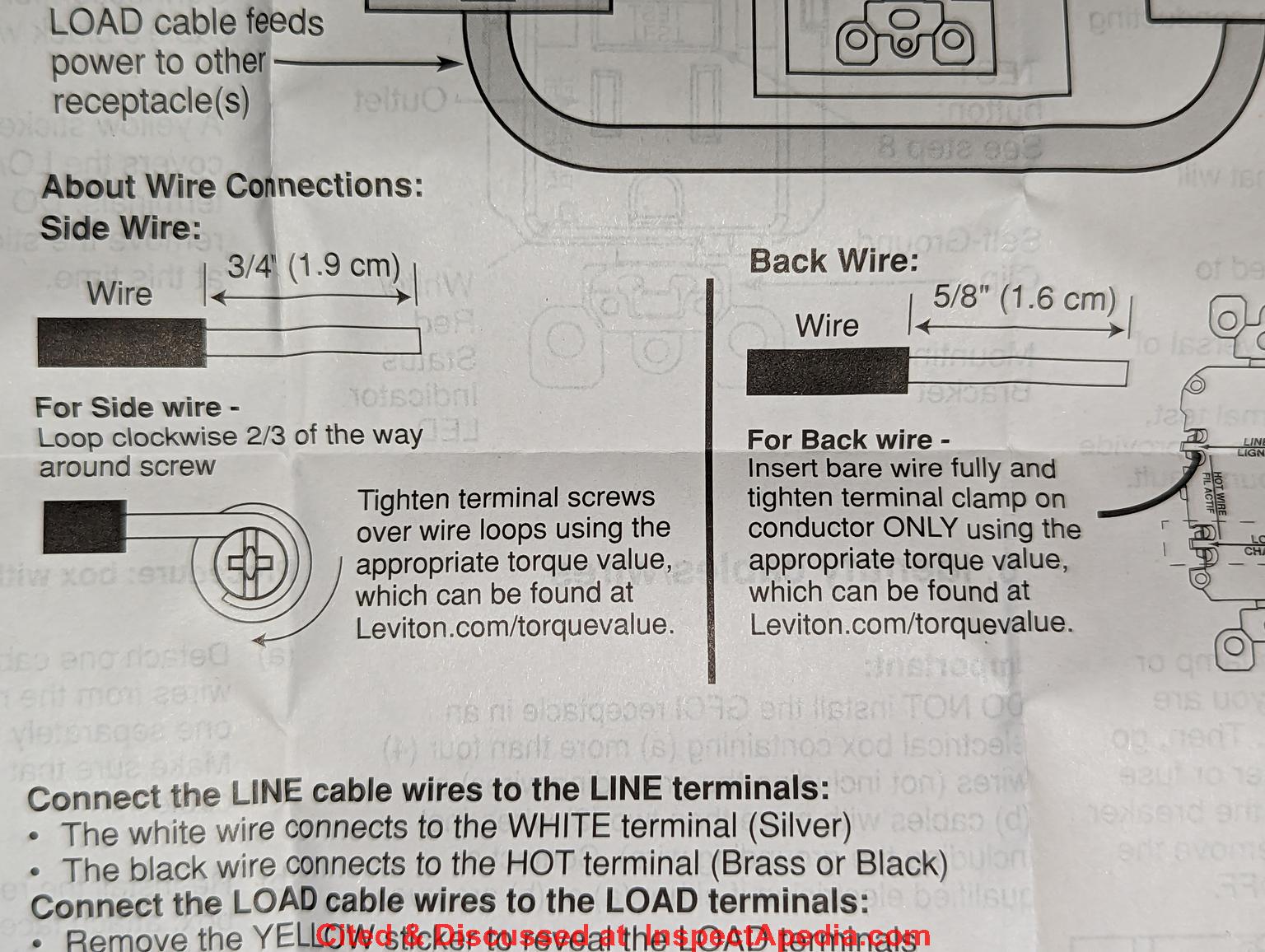
I'm the type of person who always reads all the instructions, each and every time. Heck, when I'm programming, sometimes I copy parts of the docs into the source, along with a link, so the next person to come along (usually me) can easily go and double check to see if anything has changed. I was looking at the instructions for stripping and connecting the conductors, and I noticed the wording for the side wire and the back wire screw clamp connections are very slightly but clearly different.
The side wire instructions say:
"Tighten terminal screws over wire loops using the appropriate torque value, which can be found at leviton.com/torquevalue"
(Which, as yet another sidenote, it's pretty terrible human factors engineering if you wanted people to actually torque them properly, to make people open the website on their phone and try to get the correct data. That website only works correctly for me on "desktop mode" so I've ended up looking the values up ahead of time and writing the specs on the cardboard boxes. )
The back wire instructions say:
"Insert bare wire fully and tighten terminal clamp on conductor ONLY using the appropriate torque value, which can be found at leviton.com/torquevalue"
The emphasis is not mine. Seeing that unexplained change is one of the things that got me thinking about this.
Coming from an electronics background, and with a healthy dose of crippling OCD, I've always had some varying degrees of unease about most electrical connections. The thought of electrical fires has occasionally kept me up at night since I was little! It wasn't until I was able to feel myself how tight the connections were under one of the higher end wire nuts that I started to worry less... And yet, I still can't find out how much clamping force that wire nut is actually exerting to squeeze those copper conductors together. I can't figure out how it's in the NEC to tighten the screws down to a consistent torque, but the wire nut is "twist until the wires twist and call it a day, she'll be good".
While sitting there, all dusty and frustrated from trying to cajole a hook loop under the screw of a leviton receptacle with VERY cramped terminal guards, I couldn't figure out which one would be the safer of the two. The wording differences suggest to me that they have some bad experience behind it, and I want as much of a safety wiggle room as I can get.
I knew from inspectapedia that the wire loop is the option with more contact area, so I went for the extra hassle in the meantime, and have kept thinking about it.
From experience, it still does feel kinda satisfying when I'm screwing down on the hook loop and it starts to suck under the screw. The fact that I usually have to counter-tension the wire with a finger or two to get the sucking effect gives me further confidence that I'm actually clamping down on the copper itself, and not actually expending effort stripping out the threads or deforming the clamping plate.
"(Anyone who has slipped off of a hand-held receptacle and stabbed himself in the hand will have improved the tightening regimen since then - more on this below.)"
*Raises hand* heh, yes, that's definitely me. It didn't help that apparently the cheap receptacles in the 80s used slotted screws where the "slotted" part was more of a "good impression" of a slot than something useful for driving threaded fasteners. And it's also why I was simultaneously elated and furious to discover that the high end receptacles also accept square drive bits.
Hey, leviton, if you're reading this, you should definitely advertise that fact. It's mentioned nowhere but it's really darn useful.
"I apologize for ducking a question for which I find no clean reliable authoritative answer,"
Apologies in no way necessary! Aside from the fact that the answer doesn't appear to exist yet, inspectapedia has gone above and beyond to provide excellent, useful, and authoritative, info. For the past ten years, since I decided to finally, begrudgingly, deal with the various issues of built spaces that have plagued the family, inspectapedia has been the one source that taught me more than anything else. (My dad is an excellent industrial engineer, but not handy, so, there's much more than 10 years worth of problems)
Maybe one day tension indicating fasteners will come down in price enough to make it into outlets. That would be neat. But they're still ~$26 each on McMaster-Carr, so...
On 2023-04-13 by InspectApedia Editor - how much torque for binding-head screws on receptacles and switches
@Alexander Riccio,
Thank you so much for the helpful and interesting discussion about binding-head screws on receptacles and switches.
The amount of torque that an installer can provide to the screws on an electrical receptacle, without using a measuring tool, varies by orders of magnitude depending on just how the connection is being made. For example: are you holding the receptacle in one hand, out from the wall while connecting each wire, or is the receptacle pressed against a wall, floor, or ceiling surface during that operation.
(Anyone who has slipped off of a hand-held receptacle and stabbed himself in the hand will have improved the tightening regimen since then - more on this below.)
I bought an SK torque screwdriver to do some of the tests for this article series, but other than myself and Dr. Jess Aronstein, in fifty years of work around construction and building forensic topics, I've never met a single electrician who owned a torque-measuring screwdriver, and most whom I've asked have never even heard of such a device.
OPINION: So I agree with you that everything else in instructions for hand-tightening screws at electrical connectors is very subjective and may be considerably variable.
King Innovations, describing using their AlumiConn tried to address this problem of adequate torque for that case (an aluminum wire repair product) by saying to turn the screw down snug to the wire and give an additional specific amount of rotation - but my tests showed that was just about as subjective and variable as before that advice.
OPINION: And tightening screws on receptacles and switches myself, I've ruined enough of them to prefer to avoid the low-cost models.
OPINION: So we're stuck with suggesting buying the best quality devices you can find, watching out that even some of those now made "offshore" (you know where) may be as flimsy as their low-budget cousins, and tightening enough that if you wiggle a wire it remains firmly connected.
Watch out: in some more-recent tests I found that with the newer clamp-type connections at receptacles - a design intended to permit "back-wiring" into a screw tightened connector that gives much better contact area than the teeny spring-clips in the low-budget cousins, it was way too easy to over-tighten, stripping the clamp fitting so that I thought the connection was tight but later could pull the wire right out.
Some of those connectors overheated and one was sparking like mad in an electrical box before I shut down power and found that arcing had oxidized the surfaces around the connector plate, screw and wire enough to cause overheating and burn damage.
I apologize for ducking a question for which I find no clean reliable authoritative answer, but keep in mind that in the U.S. our electrical standards are written by the most expert people available to sit on those committees: folks who come from the electrical product manufacturers themselves.
So where are we:
An experienced electrician or other handy person who has done more than incidental electrical wiring will have tried making connections very tight and snug and will have destroyed a few devices until she or he comes to a personal opinion about "how tight can I make this without risking ruining the device" and they'll stop there.
Aronstein, who is even older than I am, has spent a lifetime on problems like this, so if he's still got the energy, I'll ask Jess if he can add any advice on tightening screws at receptacles.
On 2023-04-13 by Alexander Riccio
A few things. For some reason, wire binding screw torquing has really been fascinating me for a few months as I change out a bunch of really junky receptacles. Part of it is definitely that I've always been the person who has trouble with instructions that say "finger tight, DO NOT OVER TIGHTEN", since everybody has different fingers.
First, inspectapedia, top notch as always.
Second, I do share Roger's curiosity about applying enough clamping pressure to plastically deform the copper conductors... And it's something I've been able to do with flathead screwdrivers. Not to brag about my forearm strength. Knowing that in the automotive world, engineers like to use torque-to-yield bolts for the more consistent clamping forces, or sometimes listing "torque angle" specs, is there any value to it? I wouldn't do it normally. I'm definitely reasonably concerned about issues like damaging the binding screw, or maybe even causing some kind of work hardening and embrittlement in the conductor.
Third, maybe times have changed since a youngster like me came around, but you can get reasonably accurate torque screwdrivers on Amazon now for like 40 bucks! I wouldn't use them to screw in my dental implants, but I'm confident they're plenty accurate for the wide torque range on high end receptacles (e.g. 14-18 on fancy levitons).
Fourth: something nobody told me until after I'd changed out a dozen outlets is that the funny looking screw heads on higher end receptacles (again, like leviton) actually also accept Robertson square drive bits! I have no clue if you've noticed or tried it, but to anybody out there reading this, it's a HUNDRED times easier to hit that 18 in/lb torque when you're not bearing your whole arm down to keep the bit from camming out. The same good receptacles also have mounting screws that accept Robertson drive bits. It's the kind of thing that will save you countless hours.
Last: I'd be curious to see someone repeat the over torquing test with a top of the line extra heavy duty industrial grade or extra heavy duty hospital grade, standard NEMA 5-15 receptacle. Heck, if I end up with an extra somehow, maybe I will. But they're kinda pricey, I don't wanna trash one for no reason!
On 2020-11-01 by (mod) - Standards for Electrical Receptacle Wire-Contact Area & Torque
 Roger,
Thank you for an interesting and important comment/question. I'm doing more research and have asked for assistance but to date we have the results below that are those most-easily found.
You may also enjoy
WIRE-TO-CONNECTOR FORCE COMPARISONS - [Web Article at InspectApedia.com]
[Click to enlarge any image]
Electrical Contact Size Requirements for Electrical Receptacles & Switches
I have not found research offering a minimum area or contact size and force specification for all of the typical electrical residential wiring contacts (including push-in back-wired connections) such as found in light switches and electrical receptacles.
Without question the contact area between wire and connector in an older spring-clip push-in backwired electrical receptacle and the contact area of a round wire under a binding head screw on a similar device have to be considerably different.
And I have not found an industry standard that discusses contact surface area nor force for many wire-connector designs used in receptacles and switches (See Table I.1 above), though there are definitely manufacturer specifications that are very important such as torquing specifications for screw-in type connectors in electrical panels and in some specialty products such as the AlumiConn connector that we discuss at this website.
I’m continuing to look.
Search Results: Google Scholar,
argument:
“minimum size for electrical contacts”
and
“Standard contact area for electrical wiring connections”
Date: 2020/11/01
Selections from search results are below.
- Aronstein, J. "Evaluation of receptacle connections and contacts." In Proceedings of IEEE Holm Conference on Electrical Contacts, pp. 253-260. IEEE, 1993.
- Aronstein, J. E. S. S. E., and W. Campbell. "Failure and overheating of aluminum-wired twist-on connections." IEEE Transactions on Components, Hybrids, and Manufacturing Technology 5, no. 1 (1982): 42-50.
- Babrauskas, V., HOW DO ELECTRICAL WIRING FAULTS LEAD TO STRUCTURE IGNITIONS? [PDF] pp. 39-51 in Proc. Fire and Materials 2001 Conf., Interscience Communications Ltd., London (2001). >
Excerpts:
“The study noted that the power dissipation depends only on the materials involved and not on the nominal size of the contacts. It was also found that to start the glowing process, a current of 4 ñ 6 A had to be supplied; glowing of freshly-made connections could not be started with smaller currents.“
This author and work are discussed further
at BACK-WIRED ELECTRICAL DEVICES - Braunovic, Milenko, Nikolai K. Myshkin, and Valery V. Konchits. Electrical contacts: fundamentals, applications and technology. CRC press, 2017.
- Champion, Yannick, and Yves Bréchet. "Effect of grain size reduction and geometrical confinement in fine grained copper: potential applications as a material for reversible electrical contacts." Advanced Engineering Materials 12, no. 8 (2010): 798-802.
- Kogut, L., and K. Komvopoulos. "Electrical contact resistance theory for conductive rough surfaces." Journal of Applied Physics 94, no. 5 (2003): 3153-3162.
- Slade, Paul G., ed. Electrical contacts: principles and applications. CRC press, 2017.
and from generic search:
- NASA, WORKMANSHIP STANDARD FOR CRIMPING, INTERCONNECTING CABLES, HARNESSES, AND WIRING, NASA TECHNICAL STANDARDNASA-STD 8739.4A with Change 1, https://nepp.nasa.gov/files/27631/NSTD87394A.pdf
Excerpt:
12.3.5 Integrity of Crimped Connections.a.The following requirements apply for crimp process development when there is no recommended tool setting for the contact-conductor combination:
(1)For each new crimp process where a crimp tool setting must be determined for a contact-conductor pair (or a crimp ferrule-conductor combination), a three-sample pull test at each of the different crimp tool settings considered for use are required using the force and pull strength criteria in Table 12-1.
(2)The crimp tool setting that produces the maximum number of fray breaks and breaks outside the contact or crimp ferrule shall be used for assembly (see Figure 12-1).
(3)If multiple settings provide identical tensile strengths for a crimp joint, the setting selected shall be the one that provides more wire breaks than wire pullouts. - U.S. NEC Table I.1 Tightening Torque for Screws [PDF] Slotted Head No. 10 and Larger [Image File] Current version is at https://www.nfpa.org, 2020 Edition of the U.S. National Electrical Code, Annex I: Tightening Torque Tables
- U.S. NEC Table I.2 Tightening Torque for Slotted Head Screws Smaller than No. 10 Intended for Use with 8 AQG (8.4mm) or Smaller Conductors [PDF] U.S. National Electrical Code, 2020 Edition, available from https://www.nfpa.org
- US NEC 110.14(D) Terminal Connection Torque.
Tightening torque values for terminal connections shall be as indicated on equipment or in installation instructions provided by the manufacturer. An approved means shall be used to achieve the indicated torque value.
Informational Note No. 1: Examples of approved means of achieving the indicated torque values include torque tools or devices such as shear bolts or breakaway-style devices with visual indicators that demonstrate that the proper torque has been applied.
Informational Note No. 2: The equipment manufacturer can be contacted if numeric torque values are not indicated on the equipment or if the installation instructions are not available. Informative Annex I of UL Standard 486A-486B, Standard for Safety-Wire Connectors, provides torque values in the absence of manufacturer’s recommendations.
Informational Note No. 3: Additional information for torquing threaded connections and terminations can be found in Section 8.11 of NFPA 70B-2019, Recommended Practice for Electrical Equipment Maintenance.
On 2020-10-31 by roger newill
I'm developing a 120v electrical device (see tryhotwire.com), and I've just read your 2017 "Variations in Wire-to-Connector Contact Area on Three Electrical Receptacle Connector Types," It was very well done, illustrated, and documented.
I recognize "more is better" regarding contact area, corrosion-freeness, conductor copper content, compression, and installer precision, but the article didn't include adequacy-information or -evaluations in those matters.
How much is theoretically, demonstratedly, or presumably "enough" ? (whatever NFPA, UL, etc. feel is enough) I can see ways to increase the wire/conductor compression (for example) significantly, at a cost, but is the current 15 lbs "enough" ? ... or would "swaging the wire flatter" be far safer ? best - Roger rfnewill@gmail.com
On 2019-11-20 by (mod) - Tables in the National Electric Code (NEC) Annex I, list tightening torque for screws
Thank you for the interesting and useful comments, James.
Indeed I like Mike Holt's forum on electrical matters and will add an easy to find version of the torque article you cited.
Of course you will not find a torque wrench in the toolbox of one in 10,000 electricians. I've asked electricians individually and at conferences and classes in groups around the U.S. and Canada since the 1980s how many of them even own a torque wrench. Those few who did had it in their garage to work on their car.
AlumiConn provides an alternative torquing procedure that might work and that has seen a little independent testing.
I agree, and point out at AlumiConn TORQUE TESTS inspectapedia.com/aluminum/AlumiConn_Torque_Tests.php that (as you mention) some electrical connectors, such as the AlumiConn (search InspectApedia.com for that product) used to repair aluminum wiring (copper to aluminum pigtailing) include in the product spec a torque requirement and the designer / manufacturer has said that for that situation torque is really important.
But given that almost nobody uses a torque wrench in the field, IMO we need procedures that assure properly-torqued connections without measurement. That might be solved by features of device design, or guessed-at by more-subjective: turn it until it stops then turn 1/2 revolution more" or similar advice (AS AN EXAMPLE THIS IS NOT SOMETHING I CURRENTLY RECOMMEND).
You will be interested in this recent addition:
BACKWIRED DEVICE SPRING CLIP 1960 DESIGN
On 2019-11-20 by James Cuzella
It's really great that you've taken the time to test and share test results for the "Estimated Pressure of Binding Head or Pressure Clamp Screw to Copper Wires"!
It adds some clarity given the lack of information about proper receptacle tightening torque and uncommon practice of actually using a torque screwdriver when installing receptacles.
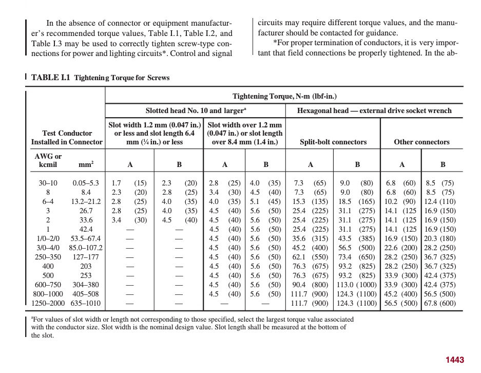
According to some Tables in the National Electric Code (NEC) Annex I, there are some listed tightening torque for screws. The best explanation for how to use these Tables (I.1, I.2) that I could find was here: https://web.archive.org/web/20191120190139/https://forums.mikeholt.com/forum/active-forums/nec/108112-annex-i-table-i-1-tightening-torque-for-screws
These tables appear to be sourced from UL connector testing procedure specifications from the UL 486 A-B standard. In the NEC, they appear to be included for informational purposes and are not believed to be commonly adhered to as part of code requirements.
However, Section 110.3(B) in the National Electrical Code requires that equipment be installed according to its listing and labeling.
If such labeling includes torque values, then it's surely included in code requirements. This is especially true when working with older aluminum wiring & Alumiconn connectors.
It's interesting to consider the effects of torque even with copper wire and standard receptacles, and poses some questions given the experimental results described in this article using 22 in*lbs of torque on a common receptacle screw. Many receptacles do not include a manufacturer's specification for torque values. Therefore, Table I.1 is recommended as a default value. The forum commenter suggests using column B of Table I.1 ("Tightening Torque for Screws"), which lists tighter torque values than column A. (See table here: https://web.archive.org/web/20191120190428/https://www.scribd.com/document/244311553/Torques-pdf )
Given column B for wire gauges between 30-10 AWG, and screw slot width 1.2 mm (0.047 in.) or less & slot length 6.4 mm (1/4 in.) or less, the table lists 20 lb-in of torque. That's pretty close to the 22 lb-in used in this article's experiment. I'd wonder if for receptacle wiring purposes column A is more applicable, given that it lists 15 lb-in which lines up with the Alumiconn connector recommended torque value.
I'd love to hear thoughts about this!
...
Continue reading at WIRE-TO-CONNECTOR FORCE COMPARISONS or select a topic from the closely-related articles below, or see the complete ARTICLE INDEX.
Or see these
Recommended Articles
- BACK-WIRED ELECTRICAL DEVICES - home
- BACKWIRED RECEPTACLE FAILURE PHOTOS
- BACKWIRED RECEPTACLE FAILURE REPORT
- BACK-WIRING FAQs for RECPTACLES & SWITCHES
- ELECTRICAL WIRE TYPES CODES USES
- RECEPTACLE WIRE-TO-CONNECTOR CONTACT AREA SIZES
- WIRE-TO-CONNECTOR FORCE COMPARISONS
- WIRE-TO-CONNECTOR PERFORMANCE SUMMARY
Suggested citation for this web page
RECEPTACLE WIRE-TO-CONNECTOR CONTACT AREA SIZES at InspectApedia.com - online encyclopedia of building & environmental inspection, testing, diagnosis, repair, & problem prevention advice.
Or see this
INDEX to RELATED ARTICLES: ARTICLE INDEX to ELECTRICAL INSPECTION & TESTING
Or use the SEARCH BOX found below to Ask a Question or Search InspectApedia
Ask a Question or Search InspectApedia
Questions & answers or comments about how to install and wire electrical outlets or receptacles in buildings.
Try the search box just below, or if you prefer, post a question or comment in the Comments box below and we will respond promptly.
Search the InspectApedia website
Note: appearance of your Comment below may be delayed: if your comment contains an image, photograph, web link, or text that looks to the software as if it might be a web link, your posting will appear after it has been approved by a moderator. Apologies for the delay.
Only one image can be added per comment but you can post as many comments, and therefore images, as you like.
You will not receive a notification when a response to your question has been posted.
Please bookmark this page to make it easy for you to check back for our response.
Our Comment Box is provided by Countable Web Productions countable.ca
Citations & References
In addition to any citations in the article above, a full list is available on request.
- Timothy Hemm has provided photographs of various electrical defects used at the InspectAPedia TM Website. Mr. Hemm is a professional electrical inspector in Yucala, CA.
- Mark Cramer Inspection Services Mark Cramer, Tampa Florida, Mr. Cramer is a past president of ASHI, the American Society of Home Inspectors and is a Florida home inspector and home inspection educator. Mr. Cramer serves on the ASHI Home Inspection Standards. Contact Mark Cramer at: 727-595-4211 mark@BestTampaInspector.com
- John Cranor [Website: /www.house-whisperer.com ] is an ASHI member and a home inspector (The House Whisperer) is located in Glen Allen, VA 23060. He is also a contributor to InspectApedia.com in several technical areas such as plumbing and appliances (dryer vents). Contact Mr. Cranor at 804-873-8534 or by Email: johncranor@verizon.net
- [5] Special thanks to our reader Steve who pointed out prior errors in our illustrations.
- In addition to citations & references found in this article, see the research citations given at the end of the related articles found at our suggested
CONTINUE READING or RECOMMENDED ARTICLES.
- Carson, Dunlop & Associates Ltd., 120 Carlton Street Suite 407, Toronto ON M5A 4K2. Tel: (416) 964-9415 1-800-268-7070 Email: info@carsondunlop.com. Alan Carson is a past president of ASHI, the American Society of Home Inspectors.
Thanks to Alan Carson and Bob Dunlop, for permission for InspectAPedia to use text excerpts from The HOME REFERENCE BOOK - the Encyclopedia of Homes and to use illustrations from The ILLUSTRATED HOME .
Carson Dunlop Associates provides extensive home inspection education and report writing material. In gratitude we provide links to tsome Carson Dunlop Associates products and services.
 | HOME | ABOUT | ASK a QUESTION | CONTACT | CONTENT USE POLICY | DESCRIPTION | POLICIES | PRIVACY | |
| © 2024 - 1985 Publisher InspectApedia.com - Daniel Friedman | |||||||||