
InspectAPedia® FREE Encyclopedia of Building & Environmental Construction, Diagnosis, Maintenance & Repair |
Question? Just ask us! InspectAPedia
|
 Backwired Electrical Outlet Failure Report
Multiple circuits "went off" in this home: why? Diagnosis & repair
- POST a QUESTION or COMMENT back-wired electrical receptacle or switch failures
Back wired electrical receptacle failure field report:
Curt Russell describes the detection and repair of electrical receptacles in a beachfront home. A combination of use of back-wired electrical outlets or receptacles and the corrosive effects of exposure of electrical wiring to salt air led to loss of electrical power.
This article series explains and documents cases of the failure mechanisms that lead to loss of electrical power or overheating and fires that occur on electrical circuits wired using back-wired electrical receptacles and switches.
InspectAPedia tolerates no conflicts of interest. We have no relationship with advertisers, products, or services discussed at this website.
Lost Power: Back-Wired Electrical Receptacle Failure & Repairs at a Beach-Front Home
 - Curt Russell July 2018
We Lost Electrical Power, Breakers Were Not Tripped
On Sunday, as we were cleaning up, the hot water went off. I went down to the utility room to see if there was a problem I could resolve.
I found that the electricity was off in the utility room which serves the controls on the hot water heater as well as the lights and receptacles in all of the closets.
The refrigerator was also off and all of the outdoor ground fault receptacles were off as well. At first, I thought maybe one of the outdoor ground fault receptacles had gotten wet.
[Photo shown provided by the author, used here with permission. ]
[Click to enlarge any image]
We had heavy rain and high winds on Saturday and through Saturday night. I pulled each of these receptacles out and tested them for current… all were dead.
I checked the breaker panel and none of the breakers were tripped - which made me very curious. I pulled the cover off of the breaker panel that fed this circuit and verified that there was juice going to the circuit - which there was.
I noticed that there is a receptacle on the wall to the right of the breaker panels that mirrors a ground fault receptacle on the outside wall.
Thinking that this receptacle might be the first in the circuit, I pulled it out to check it. As I was pulling it out, I noticed that the light in the utility room came on.
Good: I found the problem!
Not good: the problem was caused by what I consider bad electrical wiring technique by the electrician who installed the receptacle at the time of construction of the home.
I corrected the problem (by installing a new electrical receptacle using its screw terminals rather than push-in backwiring connectors), and everything is now well with this receptacle and the circuit downstream.
But this circuit is not unique. Nearly all of the switches I replaced have the same issue, and this is a serious safety (fire hazard) concern.
Two Ways to Wire Switches & Receptacles: screw terminals or back-wired push-in connectors
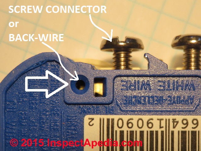 Shown in the photo: on many electrical receptacles and switches (let’s call them “devices”) sold in North America, both screw terminals and push-in type back-wire connectors are provided.
Other devices include only screw terminals, and still others previously included only push-in terminals.
So there are two ways to wire these switches and receptacles in residential circuits.
- Use the screw terminal side-wired connectors - the hot and neutral wires are connected to the device by screws located on the side of the switch or receptacle. The wire is stripped, bent into a loop around the screw, the loop is pinched closed, and the screw is tightened.
- Use the push-in back-wired connectors - the hot and neutral wires are connected to the device using a push-in connector: a hole into which a straight section of stripped wire is simply inserted.
This second connector is called a "back-wire" connection because the connector is located on the back of the device.
The wire end is stripped (a strip length gauge is provided on the device) and pushed into a hole where it is gripped by an internal spring in the device.
Avoiding having to bend the wire around a screw and then tighten the screw is a big time saver for the electrician.
There are actually four versions of push-in back-wire connectors used on receptacles and switches. Details are
at BACK-WIRED ELECTRICAL DEVICES, 4 TYPES
Many residential 15A and 20A rated receptacles and switches included and still include both screw-terminal and push-in back-wire terminal wiring connectors, giving the electrician a choice of how to connect those devices.
In the photo above, you can see the two different types of connectors provided on the same receptacle.
Watch out: In my view spring-type push-in wiring terminals are unreliable, therefore unsafe, and they should not be used.
What's Wrong With Spring-Type Back-Wire Connectors?
 The problem with back-wiring into a spring-type connector like the ones we illustrated earlier is that due to any or a combination of factors, spring force, small contact area, and corrosion, the connections can fail. "Fail" here means either loss of a functional connection or overheating at the connector.
Photo provided by the author. [Click to enlarge any image]
Watch out: Loss of connection is experienced as a loss of electrical power to the receptacles (or lights or switches) - a circuit failure like the failure we had. Worse, overheating at the connectors is a fire hazard.
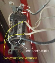
Shown here is the Beach House receptacle that failed (in the foyer, to the left of the back door going out to the utility room).
The four copper wires you were all back wired. I pulled the black wires out so you can see the corrosion on the stripped-back copper wire ends.
They look black and green - corroded. The wire-to-spring connectors may have been arcing as well.
Note also the rust and corrosion on the screws that connect the receptacle to the electrical box and the rust on the ears of the steel receptacle mounting strap: these tell us that this device was installed in a corrosive environment - consistent with exposure to damp salt air at a beach-front home.
Both arcing and corrosion could explain the black, oxidized surface shown on these wires. That oxidized surface means that the electrical connection through the stripped wire end has to pass through oxidized copper: a poor connection that risks loss of current flow (no power) or overheating (fire).
Watch out: Because this is a beach-front home on salt water, it is also likely that the exposed copper wire and all electrical connectors in this home suffers extra corrosion from the moist salt-laden air. That makes the quality and security of electrical connectors all the more important.
Wiring Electrical Receptacles In Series
When a receptacle is wired as shown in this photo, all of the circuit neutral (white) wires are connected to the neutral terminals or connectors right on the receptacle, and all of circuit hot (black) wires are connected to the hot terminals on the receptacle.
All of the current used downstream of the receptacle goes through the connectors on this receptacle - the entire circuit load.
That puts a huge electrical flow through the device. Where back-wiring connectors were used, all of that current is flowing through a tiny contact area between the spring and the wire of the the back-wire connections.
Back-wiring using the manufacturer-connections provided for that purpose is permitted by the U.S. and Canadian electrical codes.
Watch out: in my opinion the wiring practice of wiring receptacles in series and using push-in back-wire connectors is less reliable and less safe than two alternatives:
- The screw-type terminals are used for all wire connections, thus assuring that circuit current flows through a physically larger copper connector).
This wiring approach still has the risk that if any connector in the circuit fails, all of the downstream devices will also lose power. - The receptacles are wired not in series but in parallel (explained below) with the electrical circuit bringing current independently to each device on the circuit. In my view this is the best and safest wiring method.
Details of exactly how and why backwired connectors fail in receptacles and light switches are given by Friedman
at BACK-WIRED ELECTRICAL DEVICES.
Separately at RECEPTACLE WIRE-TO-CONNECTOR CONTACT AREA SIZES he explains that in addition to contact-force concerns, the very small contact area in back-wired connectors on receptacles is likely to contribute to connector failures.
Wiring Electrical Receptacles in Parallel to Improve Circuit Reliability
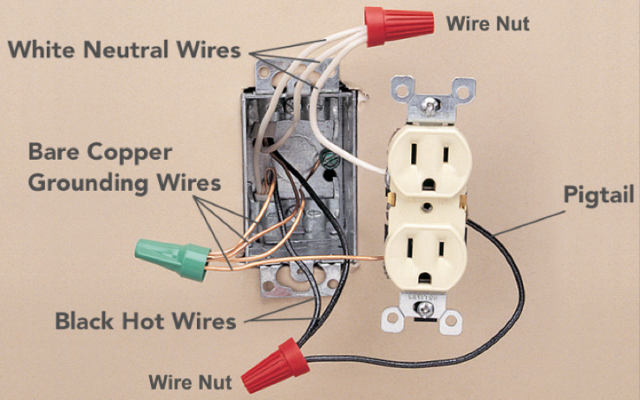 Rather than running all of the inbound and outbound wires through the device, the wires are all connected together with twist-on connectors.
Wiring uses a set of “pigtails” wired to connect the circuit conductors to the device.
In this way, the downstream circuit passes through the box without passing through the device itself. The only load on the device is whatever you plug into that device… not the rest of the circuit.
Photo provided by the author. [Click to enlarge any image]
For example, the 3 black wires left to right are as follows:
Hot coming in
Hot going out to other devices
Pigtail going only to this receptacle
The same goes for the white wires and the ground wires.
Watch out: when converting from device-wired to a parallel-wired electrical circuit in a string of receptacles, you can not use this pigtailing method unless the electrical box size is of sufficient cubic inches to contain the additional wires and connectors.
See details of wiring receptacles in series or in paralle
at ELECTRICAL RECEPTACLE WIRING SERIES vs PARALLEL
Repairs & Recommendations for Electrical Wiring & Devices in the Beach House
In the Beach House, every switch I replaced that had a downstream circuit was back-wired. The receptacles are likely done the same way. This means that the juice feeding everything downstream is passing through these devices and their back-wired connections.
Watch out: The circuit I fixed had the refrigerator, the hot water heater, all of the outdoor receptacles, the storage room receptacles and lights, and the ground floor toilet pump all going through this receptacle and these back-wired connections.
That’s a lot of juice to be passing through a receptacle, much less through a back-wired connection! That electrical circuit is overloaded.
Given the salt air environment and the amount of electrical load on your circuits, it is my opinion that the wiring in each and every receptacle and switch box should be reworked to eliminate back-wired connections as well as connections that pass through the devices.
That will require
- Removing the old devices
- Cleaning the corroded wire ends or if sufficient wire length is available, cutting off the corroded wire ends and stripping back insulation to expose new clean copper
- Installing new devices using only screw terminal type connectors, not push-in spring-clip type back-wire connectors. (Other types of screw clamp backwire connectors shown at BACK-WIRED ELECTRICAL DEVICES work safely and could be used)
I am not trying to be alarmist, but the wiring on the receptacle I fixed looked really bad. I didn’t like the wiring methods I saw elsewhere, and then this happened. It gives me a lot of concern.
The dimmer switches that are original to the house were designed for incandescent bulbs which are now nearly obsolete. These dimmers are not designed to work with new LED bulbs and the like. They will need to be replaced at some point fairly soon.
The refrigerator on the ground floor should probably be on a separate circuit. If this were new construction, a separate circuit would be required by code. While it is safe to have it as is, it consumes a lot of the capacity of that circuit which really limits what you can do with the other outside outlets, etc.
Here is what else should be done:
- Correct the wiring in each receptacle and switch box to eliminate back-wired connections as well as connections that pass through the devices.
Note: While doing this, I would change all of the switches and outlets to white devices with new modern white face plates as an aesthetic upgrade. - Replace the remaining old dimmer switches
- Run a separate circuit to the ground floor refrigerator
- ©2018 as Adapted & edited at InspectApedia.com
...
Continue reading at BACK-WIRED ELECTRICAL DEVICES - topic home, or select a topic from the closely-related articles below, or see the complete ARTICLE INDEX.
Or see these
Recommended Articles
- BACK-WIRED ELECTRICAL DEVICES - home
- BACKWIRED RECEPTACLE FAILURE PHOTOS
- BACKWIRED RECEPTACLE FAILURE REPORT
- BACK-WIRING FAQs for RECPTACLES & SWITCHES
- RECEPTACLE WIRE-TO-CONNECTOR CONTACT AREA SIZES
- WIRE-TO-CONNECTOR FORCE COMPARISONS
- WIRE-TO-CONNECTOR PERFORMANCE SUMMARY
Suggested citation for this web page
BACKWIRED RECEPTACLE FAILURE REPORT at InspectApedia.com - online encyclopedia of building & environmental inspection, testing, diagnosis, repair, & problem prevention advice.
Or see this
INDEX to RELATED ARTICLES: ARTICLE INDEX to ELECTRICAL INSPECTION & TESTING
Or use the SEARCH BOX found below to Ask a Question or Search InspectApedia
Ask a Question or Search InspectApedia
Questions & answers or comments about how to install and wire electrical outlets or receptacles in buildings.
Try the search box just below, or if you prefer, post a question or comment in the Comments box below and we will respond promptly.
Search the InspectApedia website
Note: appearance of your Comment below may be delayed: if your comment contains an image, photograph, web link, or text that looks to the software as if it might be a web link, your posting will appear after it has been approved by a moderator. Apologies for the delay.
Only one image can be added per comment but you can post as many comments, and therefore images, as you like.
You will not receive a notification when a response to your question has been posted.
Please bookmark this page to make it easy for you to check back for our response.
Our Comment Box is provided by Countable Web Productions countable.ca
Citations & References
In addition to any citations in the article above, a full list is available on request.
- Timothy Hemm has provided photographs of various electrical defects used at the InspectAPedia TM Website. Mr. Hemm is a professional electrical inspector in Yucala, CA.
- Mark Cramer Inspection Services Mark Cramer, Tampa Florida, Mr. Cramer is a past president of ASHI, the American Society of Home Inspectors and is a Florida home inspector and home inspection educator. Mr. Cramer serves on the ASHI Home Inspection Standards. Contact Mark Cramer at: 727-595-4211 mark@BestTampaInspector.com
- John Cranor [Website: /www.house-whisperer.com ] is an ASHI member and a home inspector (The House Whisperer) is located in Glen Allen, VA 23060. He is also a contributor to InspectApedia.com in several technical areas such as plumbing and appliances (dryer vents). Contact Mr. Cranor at 804-873-8534 or by Email: johncranor@verizon.net
- [3] NFPA - the National Fire Protection Association can be found online at www.nfpa.org
- [4] The NEC National Electrical Code (ISBN 978-0877657903) - NFPA might provide Online Access but you'll need to sign in as a professional or as a visitor)
- US NEC Free Access: See up.codes at this link: https://up.codes/code/nfpa-70-national-electrical-code-2020
- [5] Special thanks to our reader Steve who pointed out prior errors in our illustrations.
- [6] Simpson Strong-Tie, "Code Compliant Repair and Protection Guide for the Installation of Utilities in Wood Frame Construction", web search 5/21/12, original source strongtie.com/ftp/fliers/F-REPRPROTECT09.pdf, [copy on file as /Structures/Framing/Simpson_Framing_Protectors.pdf ]. "The information in this guide is a summary of requirements from the 2003, 2006 and 2009 International Residential Code (IRC), International Building Code (IBC), International Plumbing Code (IPC), International Mechanical Code (IMC), 2006 Uniform Plumbing Code (UPC) and the 2005 National Electrical Code."
- "Electrical System Inspection Basics," Richard C. Wolcott, ASHI 8th Annual Education Conference, Boston 1985.
- "Simplified Electrical Wiring," Sears, Roebuck and Co., 15705 (F5428) Rev. 4-77 1977 [Lots of sketches of older-type service panels.]
- "How to plan and install electric wiring for homes, farms, garages, shops," Montgomery Ward Co., 83-850.
- "Simplified Electrical Wiring," Sears, Roebuck and Co., 15705 (F5428) Rev. 4-77 1977 [Lots of sketches of older-type service panels.]
- "Home Wiring Inspection," Roswell W. Ard, Rodale's New Shelter, July/August, 1985 p. 35-40.
- "Evaluating Wiring in Older Minnesota Homes," Agricultural Extension Service, University of Minnesota, St. Paul, Minnesota 55108.
- "Electrical Systems," A Training Manual for Home Inspectors, Alfred L. Alk, American Society of Home Inspectors (ASHI), 1987, available from ASHI. [DF NOTE: I do NOT recommend this obsolete publication, though it was cited in the original Journal article as it contains unsafe inaccuracies]
- "Basic Housing Inspection," US DHEW, S352.75 U48, p.144, out of print, but is available in most state libraries.
- In addition to citations & references found in this article, see the research citations given at the end of the related articles found at our suggested
CONTINUE READING or RECOMMENDED ARTICLES.
- Carson, Dunlop & Associates Ltd., 120 Carlton Street Suite 407, Toronto ON M5A 4K2. Tel: (416) 964-9415 1-800-268-7070 Email: info@carsondunlop.com. Alan Carson is a past president of ASHI, the American Society of Home Inspectors.
Thanks to Alan Carson and Bob Dunlop, for permission for InspectAPedia to use text excerpts from The HOME REFERENCE BOOK - the Encyclopedia of Homes and to use illustrations from The ILLUSTRATED HOME .
Carson Dunlop Associates provides extensive home inspection education and report writing material. In gratitude we provide links to tsome Carson Dunlop Associates products and services.
 | HOME | ABOUT | ASK a QUESTION | CONTACT | CONTENT USE POLICY | DESCRIPTION | POLICIES | PRIVACY | |
| © 2024 - 1985 Publisher InspectApedia.com - Daniel Friedman | |||||||||