
InspectAPedia® FREE Encyclopedia of Building & Environmental Construction, Diagnosis, Maintenance & Repair |
Question? Just ask us! InspectAPedia
|
 Air Conditioning A/C System & Heat Pump Operating & Safety Controls
- POST a QUESTION or COMMENT about finding, using, repairing, or replacing air conditioner or heat pump controls & switches
Air conditioner & heat pump controls & switches:
This article explains the function, location, identification & use of all air conditioning & heat pump system operating controls. Photos and text help you to find & recognize each of these controls and the text explains what the control does.
What are all of the controls and switches found on A/C & heat pump systems, where is each control found, what does it do, and which controls should be used by the building occupants. Air conditioning safety switches.
Rules of thumb for sizing air conditioner fuses or circuit breakers.
Examples of "hidden" or hard-to-find switches or controls on heating & cooling systems.
We include links to detailed diagnosis & repair articles related to the various HVACR controls & swtiches. We also review the basic air conditioning safety switches, contactors, relays, refrigerant metering devices, motor overolad switches, relays, resets.
InspectAPedia tolerates no conflicts of interest. We have no relationship with advertisers, products, or services discussed at this website.
List & Purpose of All of the Air Conditioning & Heat Pump System Operating & Safety Controls
This chapter is part of our extensive air conditioning inspection, diagnosis, & repair document which describes the inspection, diagnosis, and repair of residential air conditioning systems (A/C systems) for home buyers, owners, and home inspectors.
[Click to enlarge any image]
If your air conditioning or heat pump system has lost its cooling capacity or won't start
see REPAIR GUIDE for AIR CONDITIONERS.
See COOLING CAPACITY, RATED of air conditioning equipment if the system seems to be working but is inadequate to cool your building.
Contact us to suggest text changes and additions and, if you wish, to receive online listing and credit for that contribution.
Also see A/C - HEAT PUMP CONTROLS & SWITCHES where we list all Air Conditioning & Heat Pump System Controls & Switches,
and see THERMOSTATS.
Basic air conditioning inspection and inspection report information for A/C controls:
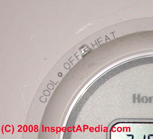
- Thermostats:
The air conditioning system is operated by thermostat in the living area. If multiple air handling units and compressors are installed you should find a thermostat for each area served by that equipment.
See THERMOSTATS for details about thermostatic controls.
If your Air conditioner or heat pump won't turn on or off properly this is a good place to start.
Also see A/C - HEAT PUMP CONTROLS & SWITCHES
- Air conditioning system zone dampers:
Some air conditioning system designs may use a single air handler and compressor, but may add zone dampers in the duct work to provide individual "zoning" of cool air distribution. In this case each zone thermostat both calls for the system blower/compressor to operate and also causes a motorized zone damper to open to direct cool air to a particular portion of the building.
An ordinary home inspection is unlikely to address proper operation of motorized zone dampers.
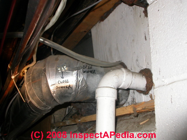
See ZONE DAMPER CONTROLS for details about automatic and manual heating and air conditioning air zone controls. - Manual or automatic duct dampers
may also be present in duct work to manually (or automatically under thermostat control) open or close to balance heating or cooling air distribution among building areas.
Be sure to look for these duct dampers when diagnosing poor cool air delivery to an area.) Also see our note below about the presence of multiple switches and controls.
See ZONE DAMPER CONTROLS for details about automatic and manual heating and air conditioning air zone controls.
- Electrical switches for air conditioning systems will often be found as follows: (some of these may be absent on some systems).
For details
see A/C - HEAT PUMP CONTROLS & SWITCHES
- Electrical panel circuit breakers or fuses will be provided separately to control the air handler (blower system) circuit and the compressor/condenser circuit. Of these the compressor is usually supplied by a 240V circuit and the air handler by a 120V circuit.
- Compressor safety shut off switch
outside at the compressor/condenser. The switch may be a circuit breaker, fuse, or a simple "pull-out" disconnect located close to the compressor.
See details at COMPRESSOR DISCONNECT SWITCH - Air handler service switch inside on or close to the air handler unit itself
- Air handler blower compartment safety switch:
a safety interlock that will turn off electricity to the air handler or blower unit if the blower compartment door is not securely shut. If your air conditioner blower will not start this switch and the blower compartment doors should be checked.
See BLOWER FAN OPERATION & TESTING - Air conditioner/heat pump contactor relay switch:
turns on high amp drawing equipment such as the compressor motor.
See CONTACTOR RELAY DIAGNOSIS & REPAIR - Air conditioner or heat pump pressure control safety switch:
turns off the system at excessive refrigerant pressure and in some systems at too-low pressure. Also used in automotive air conditioning.
See A/C - HEAT PUMP CONTROLS & SWITCHES
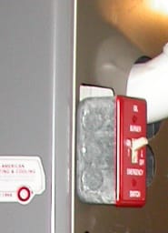
- "Hidden" controls on air conditioning & heat pump systems:
HVAC equipment also includes internal or "hidden" (from the user) controls and switches that are necessary for proper system operation. Just knowing that these items exist is the first step in diagnosing & repairing an air conditioner, heat pump, refrigerator, freezer or other HVACR equipment that is not working or not working properly.
These controls are also discussed in detail at InspectApedia, in individual HVACR diagnosis and repair articles of the major components of the system where the controls appear or are used. Examples include - Blower door safety swtich (described above)
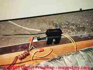
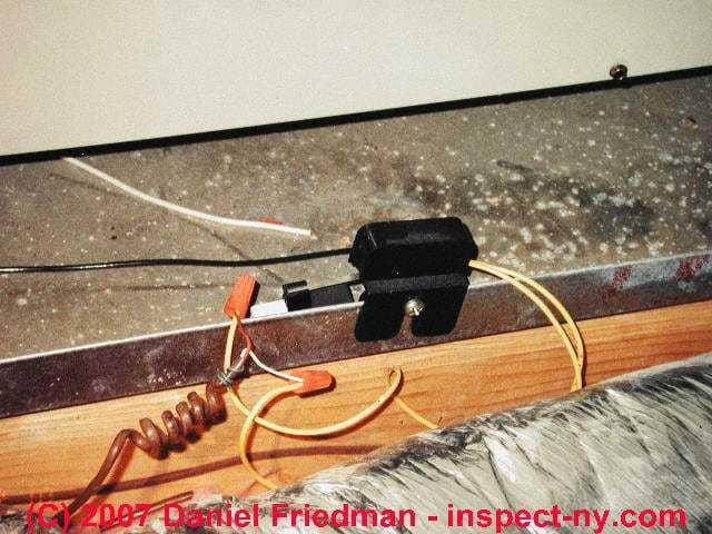
- Condensate overflow tray safety switch
or condensate pump float switch - a failure of the overflow tray sensor and switch can leave the A/C system mysteriously "off" but it's a simple repair - a photo of this switch is shown at the top of this page - Fan limit switch
on an air handler used for both heating and cooling; many of these switches, intended for use during the heating cycle, include a manual "fan-on" control that can be used to turn the blower to a constant-on position during the cooling season - Fuses, circuit breakers, thermal overload devices and "reset switches"
are built into or sometimes wired near the compressor motor, and electric motors such as fan or blower motors - Relays/contactors
- heavy duty electrical switches that turn on high-current drawing devices such as the compressor motor and sometimes the condenser/comperssor cooling fan - Thermostatic expansion valve or capillary tube -
meters refrigerant flowing through the system.
Air Conditioning Automatic Safety Controls - Cooling System Fuse or Circuit Breaker Size Requirements
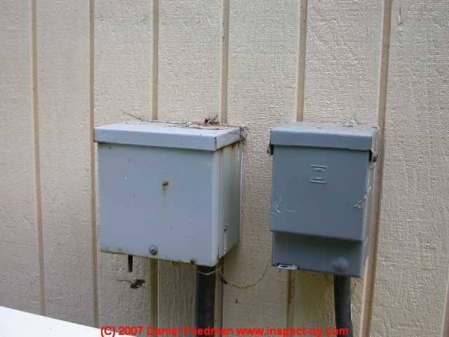
Electric Power Controls - Safety Disconnects for Air Conditioners
Safety disconnects
should installed outside next to the compressor/condenser unit and are often also installed
next to or mounted on the air handler/blower unit.
If you cannot find an outside electrical disconnect at your compressor/condenser unit, one should be installed.
These controls are recommended for safety to reduce the temptation to open the cabinet and work on the equipment with power on.
Working on electrically "live" cooling equipment risks both shock and mechanical injury such as being cut by the fan if the motor starts unexpectedly. Safety shutoffs are required for new equipment.
See A/C - HEAT PUMP CONTROLS & SWITCHES for details.
Also see COMPRESSOR DISCONNECT SWITCH
How to Specify the Breaker or Fuse Size for Air Conditioning Circuits
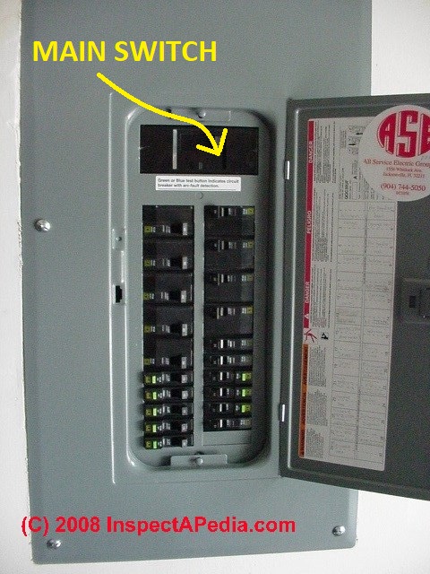
Our photograph of a modern circuit breaker panel (left) shows where your search for the air conditioning or heat pump system main circuit breakers would typically begin. Look for two control circuits for the air conditioner or heat pump system that will typically include:
- A circuit, 120V or 240V serving the indoor air handler
- A circuit, usually 240V, serving the outdoor compressor/condenser unit.
The Amperage Rating of safety disconnects and A/C or Heat Pump circuit breakers
The safety switch on newer equipment may be a simple pull-out fuse-block type power disconnect, leaving circuit protection to be provided only at the circuit breaker or fuse for the A/C circuit where it originates in the electrical panel.
Where the actual overcurrent protection is provided (at older circuit breakers used as auxiliary safety disconnects at the equipment, and at the main panel at the origin of the cooling circuit for the compressor/condenser unit) electrical overload protection size (circuit breaker or fuse amperage rating) for modern A/C equipment is specified by the manufacturer.
The Maximum Fuse or HACR type Breaker: specifies the maximum overcurrent protection or MOP to be used to protectthe equipment.
The permitted ampacity of the equipment electrical circuit protection (fuse or circuit breaker amps)expressed as MOP or Maximum Overcurrent Protection.If MOP is specified, the breaker or fuse protecting the equipment should match this number.
As we explained at the beginning of this document, a hermetic compressor draws varying amounts of current (measured in amps) as its internal pressure changes during operation.
We said that current draw is higher when starting the motor than when the system is in steady state operation.
Current draw is highest if the motor is starting against its highest back pressure such as if the air conditioning system has been turned off and then back on in the middle of operation.
Because fusing an air conditioning compressor at the minimum level can result in blown fuses or tripped breakers during these intervals of heavy current draw during compressor startup, compressors are either protected by a slow-blow fuse or a somewhat larger than minimum circuit breaker.]
Rules of thumb for over sizing air conditioning system breakers or fuses:
On some older equipment MOP is not specified. Only when MOP has not been specified can the overcurrent protection required be determined by alternative means such as [RLA OR BCSC whichever is greater x 175%], or if the compressor keeps tripping that device or blowing that fuse, RLA x 225% might be used.
The National Electrical Code (NEC) specifies the degree to which a breaker or fuse may exceed the RLA. [For example, if the MOP or fuse size is specified by the manufacturer to be 40 amps, then a 40 amp breaker must be installed with no increase or change in that rating.]
Multiple switches are often present on cooling systems. As we reminded in the previous chapter, if the air conditioning system won't run, before requesting a service call check all of the switches as well as the thermostat for proper settings.
Air Conditioner Fuse or Circuit Breaker Size Details
 Generally, what is the ampacity we see in the field when inspecting an air conditioning compressor circuit?

When the air conditioning system is running, if you measured the amperage, it would be roughly 80% of the RLA. The breaker size is typically about 125% of the total of the compressor RLA and the condenser fan FLA (full load amperage).
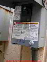
We are referring here to the main circuit breaker that controls the air conditioner compressor/condenser unit - a switch that is typically located in the main electrical panel or in a sub-panel serving the air conditioning or heat pump equipment.
Our photo at left shows a different switch: an outside service switch that incorporates a circuit breaker next to the compressor/condenser.
This circuit is for use by the service technician and because it is downstream of the wire bringing power to the compressor/condenser unit, it is not protecting that wire from an overcurrent. While both of these circuit circuit breakers must be properly served, don't confuse their role nor their location.
The rationale is that the circuit breaker protecting the air conditioner compressor unit should trip in the event of a locked rotor [the revolving axle of a compressor motor, for example] or some significant electrical event, but should not trip during start up loads which, as we know can be significantly higher than the RLA momentarily [as the compressor motor draws higher amperage to get itself started].
Why can we put an "oversized" fuse or circuit breaker on an air conditioning compressor circuit?
An air conditioning electrical circuit is different than a general household circuit in that we have a known current load.
[There is only one device connected to the air conditioning electrical circuit, and we can read its operating characteristics.] We are not worried about an overload situation where people plug several appliances into receptacles on a single circuit. Generally speaking, the amperage draw is fine or is way too big.
Code Citatin: Section E3602.10 of the IRC says,
Branch circuits for air conditioning and heat pump equipment. The ampacity of the conductors supplying a multi motor and combination load equipment shall not be less than the minimum circuit and capacity marked on the equipment.
The branch-circuit overcurrent device rating shall be the size and type marked on the appliance and shall be listed for the specific purpose." In short, do what it says on the data plate.
Thanks to Alan Carson, Carson Dunlop Associates [Toronto, carsondunlop.com ] for these details.
...
Continue reading at THERMOSTATS, HEATING / COOLING or select a topic from the closely-related articles below, or see the complete ARTICLE INDEX.
Or see A/C & HEAT PUMP OPERATING CONTROLS FAQS - questions and answers posted originally on this page.
Or see these
Recommended Articles
- A/C & HEAT PUMP OPERATING CONTROLS thermostats, zone dampers, and circuit breakers on air conditioners and heat pump systems.
- AIR CONDITIONING & HEAT PUMP CONTROLS & SWITCHES full set of all controls
- COOLING & HEATING CONTROL & SWITCH INDEX
- MANUALS & PARTS GUIDES - HVAC - home - Master Index to All Brand Names & HVAC manuals, wiring diagrams, installation and repair guides
- OIL BURNER MANUALS
Suggested citation for this web page
OPERATING CONTROLS, A/C & HEAT PUMP at InspectApedia.com - online encyclopedia of building & environmental inspection, testing, diagnosis, repair, & problem prevention advice.
Or see this
INDEX to RELATED ARTICLES: ARTICLE INDEX to AIR CONDITIONING & HEAT PUMPS
Or use the SEARCH BOX found below to Ask a Question or Search InspectApedia
Ask a Question or Search InspectApedia
Try the search box just below, or if you prefer, post a question or comment in the Comments box below and we will respond promptly.
Search the InspectApedia website
Note: appearance of your Comment below may be delayed: if your comment contains an image, photograph, web link, or text that looks to the software as if it might be a web link, your posting will appear after it has been approved by a moderator. Apologies for the delay.
Only one image can be added per comment but you can post as many comments, and therefore images, as you like.
You will not receive a notification when a response to your question has been posted.
Please bookmark this page to make it easy for you to check back for our response.
Our Comment Box is provided by Countable Web Productions countable.ca
Citations & References
In addition to any citations in the article above, a full list is available on request.
- Modern Refrigeration and Air Conditioning, A. D. Althouse, C.H. Turnquist, A. Bracciano, Goodheart-Willcox Co., 1982
- Principles of Refrigeration, R. Warren Marsh, C. Thomas Olivo, Delmar Publishers, 1979
- Refrigeration and Air Conditioning Technology, 5th Ed., William C. Whitman, William M. Johnson, John Tomczyk, Cengage Learning, 2005, ISBN 1401837654, 9781401837655 1324 page
- In addition to citations & references found in this article, see the research citations given at the end of the related articles found at our suggested
CONTINUE READING or RECOMMENDED ARTICLES.
- Carson, Dunlop & Associates Ltd., 120 Carlton Street Suite 407, Toronto ON M5A 4K2. Tel: (416) 964-9415 1-800-268-7070 Email: info@carsondunlop.com. Alan Carson is a past president of ASHI, the American Society of Home Inspectors.
Thanks to Alan Carson and Bob Dunlop, for permission for InspectAPedia to use text excerpts from The HOME REFERENCE BOOK - the Encyclopedia of Homes and to use illustrations from The ILLUSTRATED HOME .
Carson Dunlop Associates provides extensive home inspection education and report writing material. In gratitude we provide links to tsome Carson Dunlop Associates products and services.
 | HOME | ABOUT | ASK a QUESTION | CONTACT | CONTENT USE POLICY | DESCRIPTION | POLICIES | PRIVACY | |
| © 2024 - 1985 Publisher InspectApedia.com - Daniel Friedman | |||||||||